Wireless Network Requirements and Solutions for the Future Circular Collider:A Hostile Indoor Environment
Ahmed Bannour,Yichuang Sun
1 University of Carthage InnovCom Laboratory,Higher School of Communications of Tunis,Sup’Com,Cit´e Technologique des Communications Route de Raoued Km 3,5 2083 El Ghazala Ariana Tunisie Tunis,Tunisia
2 University of Hertfordshire,School of Engineering and Technology,Hatfield,Herts,AL10 9AB,UK
Abstract:The European organization for nuclear research(CERN)is planning a high performance particle collider by 2050,which will update the currently used Large Hadron Collider(LHC).The design of the new experiment facility includes the definition of a suitable communication infrastructure to support the future needs of scientists.The huge amount of data collected by the measurement devices call for a data rate of at least 1Gb/s per node,while the need of timely control of instruments requires a low latency of the order of 0.01μs.Moreover,the main tunnel will be 100 km long,and will need appropriate coverage for voice and data traffic,in a special underground environment subject also to strong radiations.Reliable voice,data and video transmission in a tunnel of this length is necessary to ensure timely and localized intervention,reducing access time.In addition,using wireless communication for voice,control and data acquisition of accelerator technical systems could lead to a significant reduction in cabling costs,installation times and maintenance efforts.The communication infrastructure of the Future Circular Collider(FCC)tunnel must be able to circumvent the problems of radioactivity,omnipresent in the tunnel.Current technologies transceivers cannot transmit in such a severely radioactive environment.This is due to the immediate destruction of any active or passive equipment by radioactivity.The scope of this paper is to determine the feasibility of robust wireless transmission in an underground radioactive tunnel environment.The network infrastructure design to meet the demand will be introduced,and the performance of different wireless technologies will be evaluated.
Keywords:future circular collider;LHC;tunnel;low latency;harsh indoor;wireless communications.
I.INTRODUCTION
The Future Circular Collider(FCC)is a complete design study of the project that will succeed the Large Hadron Collider(post-LHC study)which plans a new tunnel of 100 km long.This study is open to all scientific institutes,regardless of their size or country of origin.Currently,57 institutes participate,representing 22 countries.The future particle accelerator will be a 100 km long and come into operation after the present Large Hadron Collider ceases use the middle of the 21st century.This paper deals with the requirements to handle wireless reliable voice,data,and video transmission in a tunnel of this length to ensure timely intervention,and immediate feed to upper tiers.In addition,using wireless communications for voice,control and data acquisition of the accelerator technical systems could lead to a significant reduction in cabling costs,installation times,and maintenance efforts.
The Future Circular Collider Innovation Study(FCCIS)design study will contribute to the development of a road-map for the design and implementation plan of a new research infrastructure that will serve as the basis for the study of research areas.The proposed infrastructure,a 100 km long tunnel,completed by around ten surface sites,would initially house an electron-positron collider(FCC-ee)allowing precise measurements of the properties of the Higgs boson and other particles of the Standard Model.A proton collider at the high energy frontier(FCC-hh)would then come,capable of reaching collision energies of 100 TeV or more thanks to development work in super-conducting magnets.This study will validate in a sustainable manner the parameters essential to the realization of particle accelerators,and will open up prospects for co-development with industry on the technologies required.
This paper discusses the feasibility of a robust wireless transmission in an underground radioactive tunnel environment and presents the network infrastructure requirements to meet the demand.In fact,the underground tunnel can be considered as complex environment where multi-path,attenuation,reflection,diffraction and scattering effects are dominant.Wireless transmission in hostile indoors is subject to various damage and distortion caused by the infrastructure deployed at many locations.Inter-Symbol-Interference(ISI)is a common problem and causes a limitation of speed in high data rate communications[1].To predict the position and the exact number of the needed base station,the typical method is to estimate radio coverage.The requirements for non-line-of-sight(NLOS)situations raise havoc with tunnel wireless transmissions due to either absorption and/or multi-path reflections.Harsh indoor cases are still to be investigated.We can attribute this handicap first to operators main objective,which is to cover places where only a mass of people live.Second the leaky feeder,used in such infrastructure,was considered as a trusty solution to serve tunnels,corridors and hostile mines.Third measurement campaigns and radio propagation tests are not easy to realize,because this can disturb the current network traffic and reduce performance.Again leaky feeders cannot maintain communication when a disaster occurs;hence the hostile area will be disconnected from the external world.
The phenomenon becomes more relevant in radioactive areas.The(α,β,γ)radiation,issued from radioactive experiments,can damageimmediatelyany active devices installed in the area such as base stations and can defect as well,in a few months,any passive devices used like Leaky Feeder.Leaky feeders cannot maintain communication when a disaster occurs;hence the hostile area will be disconnected from the external world.For this reason the IT operators consider to install a large number of RF stations and encourage researcher to establish a new and innovative solution for radio propagation modelling[2].The existing Large Hadron Collider(LHC)tunnel will help to develop and to evaluate suitable technologies monitoring the future FCC tunnel.Henceforth the objective of this paper is to provide inputs for the optimization of the FCC wireless network infrastructure.
II.THE NEW HIGH COLLIDER REQUIREMENTS
From wireless communication level point of view,the New High Collider design is illustrated as shown in figure 1 which can give some insights.The new ring will be shaped from 64 alcoves with 100 km long and 100 m underground.All active devices are stored in alcoves to be isolated from radioactive zones.A high magnetic field and radiation will be exposed to the entire tunnel and particularly to experimental areas during accelerator run.Henceforth active devices such as electronics cannot be installed in the main tunnel to avoid the risk of damage and they should be shielded in alcoves.Moreover to increase safety in the tunnel,access should be limited and the number of RF modules installed must be minimized and remotely controlled.High throughput is primordial to the operation of FCC’s accelerators,during normal running and also during maintenance.The proposed solution should take into consideration the new ring constraint and restrictions summarized as below:
·We needvery high data rate ≈Terabit Per Second[Tbps]at end nodes andvery low latency<0.01msbetween nodes.
·We have only 64 alcoves to be used for shielding active devices among them the end nodes
·We should check the robustness of the transceiver againstradiation level,since end nodes are considered as active devices.
·We presume alcoves are totally isolated from tunnel.This will transform alcoves to a Faraday cage and radio signals cannot be handled.
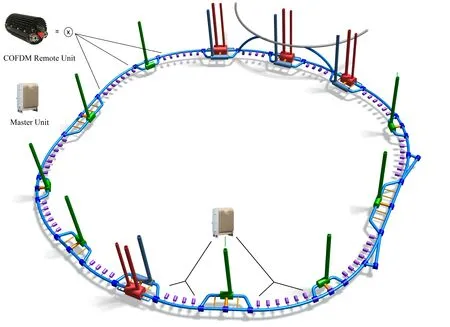
Figure 1.Proposed FCC topology.
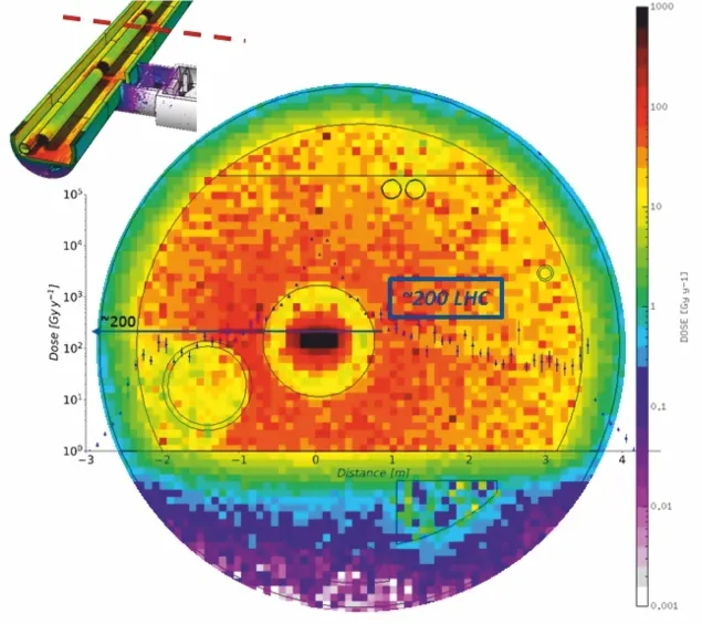
Figure 2.FCC radiation level.
When designing the wireless links of the FCC ring,we should be aware about the radiation levels in some critical areas as showed in figure 2.The electronics devices(active equipment)are immediately destroyed when the electron dose is high.One can refer to the current LHC and High Energy Hadrons(HEH)to scale the electron dose as follows:
Electron dose(long-term effects):
·Tunnel:factor 200 LHC(power converter locations).
·Alcove:factor 3-6 LHC RE(Restart)areas at the entrance of the maze,more efforts needed for the rack locations.
High Energy Hadrons(Single Event Effects):
·Tunnel:HEH 500 LHC.
·Alcove:HEH 3-4 LHC RE areas,neutrons dominate the particle environment.
III.WIRELESS COMMUNICATION SCENARIO FOR FCC
By 2050,the starting operational date of the new accelerator many mobile and radio services will be deployed,such as 5G and 6G.To guarantee a robust propagations of signals in such a harsh tunnel an antenna cable infrastructure should be used.
An antenna cable is defined as a coaxial cable,where electromagnetic signals paving the cable are transmitted over the space[3—5].The coaxial cable is considered as a passive device andcan be used in radioactive zones.Manufacturers can guarantee at least11 yearsof FCC operation.Nevertheless the RF equipment at FCC’s indoor will use the antenna cable network,combiners and splitters and will share all radio services but cannot operate in the same frequency bands,normally ranging from 400 to 900 MHz.It will be difficult to locate the suitable RF devices to properly run all the needed services.Henceforth a careful network design should be performed.
The idea is to install the equipment generating the RF signals on the surface,close to experiments areas in tunnel.At those points the RF equipment are smoothly fed and the solution will help to avoid the burden for maintenance and upgrades.But the 8 pits of the FCC tunnel,distant from each other around 3 km,seems to be insufficient,as shown in figure 1 to overcome the radiation levels of this new accelerator.The base stations used on surface would not ensure reasonable network coverage throughout the 100 km tunnel.
3.1 Analysis of Existing Solution:LHC
The current LHC will serve as benchmark to FCC wireless solution.Table 1 gives an overview as to how demanding the FCC tunnel will be in terms of data rate for IP equipment and help to design the future IP FCC wireless-based network(Supervision area).The European Organization for Nuclear Research CERN is the biggest particle physics laboratory.CERN operates three particle experiments:the Large Hadron Collider(LHC),the Super Proton Synchrotron(SPS)and the Proton Synchrotron complex(PS).Onehundred ffiteen metersunderneath the ground and with 27 km long,the LHC was installed and presents the main CERN ring.It hosts four big caverns,where residing detectors of SPS and PS[6].
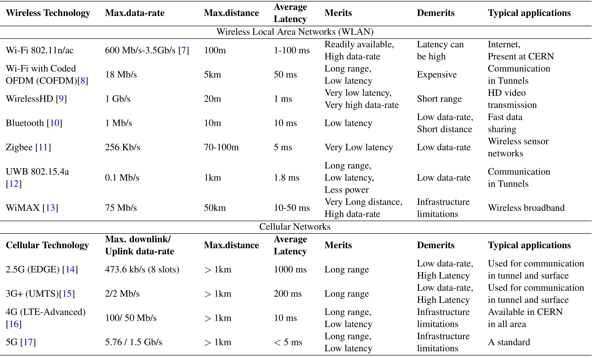
Table 1.Characteristics of available and coming up communication systems with respect to CERN requirements.
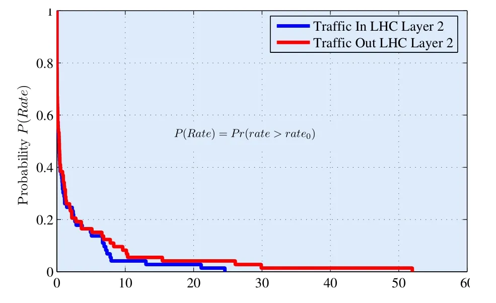
Figure 3.Data rates(Observations in monitoring dashboard)[Gbps].
Statistics of figure 3 are supposed to be an average during one year in current LHC.All the LHC traffic is considered in this scenario,including both critical and non-critical communications.Data was obtained using CERN dashboard for network traffic.The collected data was cleaned and treated using Matlab software.We notice that data rates∈[0...10]Gbps are the most probable to occur during one year and the traffic out is slightly more consuming and more likely to demand high rates.The information will serve as inputs in FCC wireless network design.Maintenance and experiments operations at CERN need a sustained high speed wireless networks.Unfortunately radiations levels prevent the installation of any active electronic devices,limiting access to their locations.To solve this problem Wi-Fi technology would be an excellent solution,but it cannot be used in the current CERN tunnel,because such a technology seems to be not scalable and an important part of the infrastructure would be exposed to radiations.LTE currently is used at CERN as solution to face the high throughput delivering and to avoid the direct installation of the equipment in tunnel.
Tests at CERN have demonstrated that such an installation cannot indeed meet the requirements for data transmission,offering very high speed,radio-link availability and low latency.
IV.THE ENVISIONED WIRELESS SOLUTION
4.1 Powering Considerations
The literature research dealing with powering in tunnel environment confirms that,in NLOS zone the channel follows Rayleigh’s law and in LOS zone the channel follows the Rice’s law[18].figure 5 illustrated the consumed power in dB Watt with respect to data rate and error probability.Eq.(1)describes the transmission power in function of data rateRas
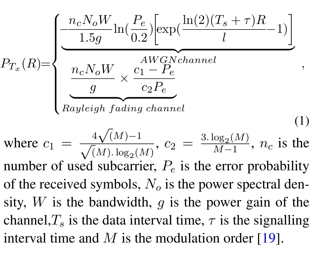
4.2 Coverage Considerations
In order to get a reliable network coverage and maintain services with good quality of service,we have to scale our network in terms of:
·Coverage(Cell Radius)
·Traffic capacity(Bandwidth)
By giving all the needed inputs which impact the attenuation level Path Loss(PL)in the FCC tunnel ,we can estimate the cell radius by

Thekvalue is a constant,in relation with CERN propagation environment.
In this solution we will assume the coverage is guaranteed by an access point/bridge.In NLOS,Radus=1.5km and in LOS,Radus=50km.Many results in literature and practical trials had demonstrated this assumption[20,21].Generally the network deployment is limited by the traffic.The number of ac-cess point/bridge used to satisfy the traffic is much higher than those dedicated to satisfy the coverage.The scale will be conducted to satisfy the required traffic.A simplified scenario is considered for design clarification and it could be more complicated.We propose,the greatest rate is for VPN services,which is 2Tbps.In the following steps we will assume the needed data rate is 2Tbps.The 2Tbps will be considered as the required data rate for any used service.At this step we have to estimate the needed bandwidth to guarantee the 2Tbps per used service and per used IP equipment in the same radius area.The total band
width is calculated as
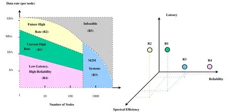
Figure 4.Tradeoff between scalability,reliability and rate.
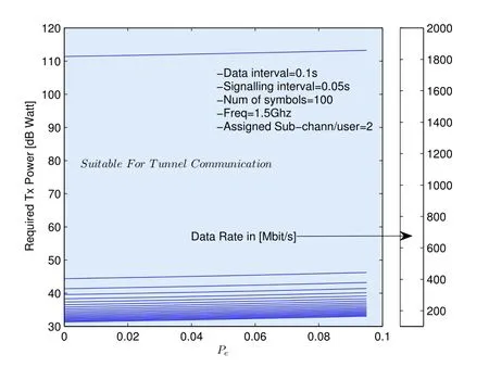
Figure 5.Scenario for TX powering for rayleigh channel type.

where
·niNumber of Equipment using IP layer for ser
vicei
·cjBandwidth reserved for servicei
·τiOccupation percentage of servicei
In the next steps we will consider that all over the time the serviceiis totally occupied(τ=1)and the needed data rate is 2Tbps.So the required bandwidth to satisfy our requirements is derived as

wherenarearefers to the number of third layer equipment in the considered area.As demonstrated by many companies in telecommunication[22—24],and by the research community,theMESH-MIMO OFDMconfiguration can
·Maintain a reliable connection in hostile environment like tunnel.
·Be combined with Wi-Fi technology via the standard IEEE 802.11a,g,j,n.
·Give to the hostile area like tunnel a good alternative toovercome the multi-path signal problemdue to NLOS problem[25].
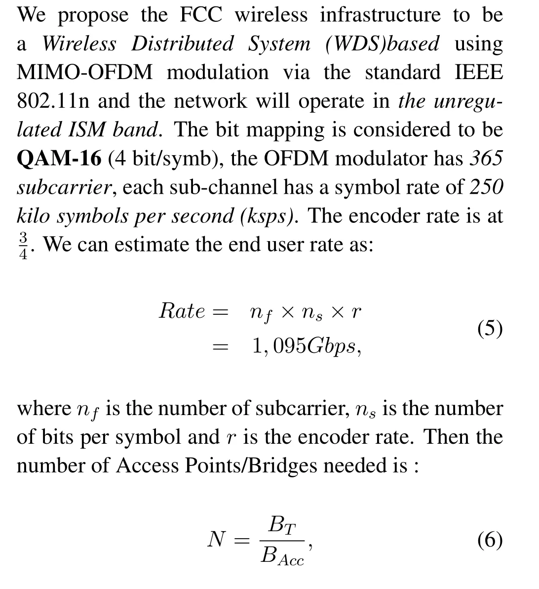
whereBTis the total bandwidth required,BAccis the bandwidth per gate or access point.A possible projection of the above methodology to the current LHC can be introduced.The region classification sorts the LHC CERN network to:
1.The General Purpose Network(GPN)- used for all standard desktop computers and most central IT services and servers.
2.The Technical Network(TN)-reserved for accelerator control systems and technical infrastructure such as access control and process control for all kinds of technical equipment ranging from ventilation to croplands.
3.One domain for each LHC experiment(Experiment Networks EN):
·ALICE-(detector controls)
·ATLAS-(detector controls)
·CMS-(detector controls)
·LHCb-(detector controls)
With respect to device count in each LHC zone as mentioned in Table 2,we can estimate the required bandwidth to maintain services.Table.3 summarizes the needed bandwidth.

Table 2.Number of IP nodes.

Table 3.Scalability and data rate by area.
V.SOLUTION AND PARTICULARITY FOR THE FUTURE FCC NETWORK
5.1 Worldfip Solution to Encompass Wireless Limitations
Table.4 shows the existence of areas in the current LHC and for sure in the future FCC,where wireless solution based on IP communication and layer 3 devices,cannot respond to the FCC specification(region 5)mainly when the required time precision(ms)crosses the barrier of 0.01μs.We stand by the required time precision,the time delivery needed to successfully handle a layer three packet to the end node.Due to this handicap,the PROFIBUS system is the unique solution as a Wireless Network for sensors and actuators.For example the WorldFIP and PROFIBUS used in the current LHC accelerator are part of the three field-buses recommended at CERN.The integration of Wireless in PROFIBUS systems(used in process automation)and Sensor/Actuator Network(WSAN,used in factory automation)are planned for the future release.A typical topology could be adopted in those areas as illustrated in figure 6.

Table 4.WorldFIP needs for the LHC machine.
The Wireless PROFIBUS based solution typically allows longer distance and robustness compared to Ethernet Connecting equipment located in the FCC tunnel or in other radioactive areas.
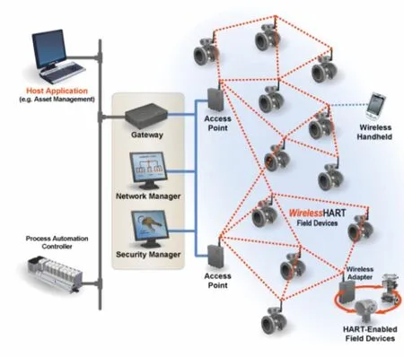
Figure 6.Possible control system architecture in FCC.
5.2 The Proposed FCC Network Infrastructure
The proposed deployment of the FCC wireless network,based on this study,is as illustrated in figure 7.On surface base stations will feed the radio frequency equipment to provide a maintained network coverage in pits areas.At the same time 5 base stations will feed a local Master Unit(MU).The main objective of MU is to convert the RF signals to optical and then handles signals to two Remote Units(RU).All RUs in the FCC tunnel should be located in”alcoves”in order to be protected from huge radiation level(4 times LHC)as discussed in Section II.Now from alcoves,the optical signal is transformed back into RF and fed to the installed RF equipment the needed coverage alongwith the 100 km circumference FCC tunnel.At the RF stage the robust modulation such as COFDM can ensure the compromise of link-availability since it was well adapted to harsh indoor.Both the FCC tunnel conception and the COFDM technology can make the presented solution robust against radiation and handle data network smoothly,with very low latency and with very high data rates.
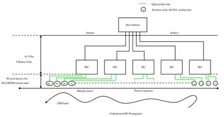
Figure 7.FCC wireless underground solution.
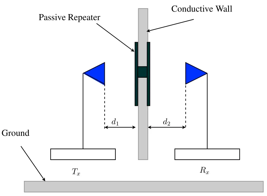
Figure 8.A possible wireless connection over metallic doors(to be used in alcoves).
5.3 Solution for Radioactive Zone with Metallic Doors
Alcoves are areas where active devices are supposed to be shielded from irradiation.It is where wireless devices are fixed.The major problem is how radio signals will propagate across the blinded doors between alcoves and the main ring(the maze).The idea is the use of passive repeaters as depicted in figure 8.Using passive repeater can:
·Improve the reliability of the wireless link throughout the tunnel.
·Avoid the use of the leaky feeder antenna and copper cables.This can reduce the cost and the time to deploy.
·Improve the QoS by improving the Bit Error Rate(BER)≈10-9)[26].
VI.CONCLUSION
The FCC study is coordinated by CERN,and seeks to investigate the design of a future particle accelerator with a 100 km circumference,which would come into operation after the present Large Hadron Collider towards the middle of the 21st century.The size of Future Circular Collider is scaled as four times the current LHC.Any proposed solution should take into consideration the time line of the project.By horizon of 2050,technology and standard will be improved in terms of rate,latency and link-availability.Wi-Fi technology is integrated in 5G standard and it will be largely used in office buildings,public locations and in 4.0 industry.It could be well adapted in large experiment halls and complex underground environments at FCC,particulary for those areas where radiation becomes an issue,such as experimental caverns.Cellular networks like LTE-A and 5G seems to be suitable to handle such a challenging environment but still to be improved in terms of date rates.In this paper,we presented an innovative network design to support the larger amount of data coming from the experiments areas.The proposed solution considers FCC constraints mainly radiation levels,harsh indoor behavior and reliability.Transmitted data should be monitored remotely while minimizing the number of active devices or even passive devices.(α,β,γ)radiations,issued from radio active experiments,can damage devices installed hence this paper will help IT FCC designers to have insights into the future of FCC network.6G may also be a promising solution for the design of future FCC.However,the radio frequencies in the THz band do not provide a very long range,although the speed and latency are quite acceptable compared to 5G.The problem of radioactivity with regard to equipments location also remains with 6G,since it is necessary to consider about the location of the Microcells and their numbers.The solution proposed in this paper is compatible with 5G and 6G solutions,since we have tried to circumvent the problems of destruction of transceiver by radioactivity.In the future,as 6G further evolves,the most appropriate transmission technique may be developed in terms of latency,data rates and scalability.
ACKNOWLEDGEMENT
To all IT-CR-TR members,and special thanks to:V´eronique Lefebure,Marwan Khelif,Stephano Agosta,Mohssen Souayah,Hubert Odziemczyk,John Shade,and Dr.Tony Cass.
From safety:Dr.Micheal Plagge(HSE-SEE-XP).From Control:Mr.Silvia Grau(BE-ICS-AS),Mr.Denis Raffourt(BE-ICS-AS),Mr.Fernando Varela Rodriguez(BE-ICS-CIC),Mr.Enrique Blanco Vinuela(BE-ICS-AP)and Mr.Frederic Chapron.
- China Communications的其它文章
- Catalyzing Random Access at Physical Layer for Internet of Things:An Intelligence Enabled User Signature Code Acquisition Approach
- Time-Domain Dual Component Computation Diversity Based on Generalized Hybrid Carrier
- On the Performance of Active Analog Self-Interference Cancellation Techniques for Beyond 5G Systems
- Multi Object Tracking Using Gradient-Based Learning Model in Video-Surveillance
- A Task-Resource Joint Management Model with Intelligent Control for Mission-Aware Dispersed Computing
- Research on Online Education Consumer Choice Behavior Path Based on Informatization

