Device design based on the covalent homocoupling of porphine molecules∗
Minghui Qu(曲明慧),Jiayi He(贺家怡),Kexin Liu(刘可心),Liemao Cao(曹烈茂),†,Yipeng Zhao(赵宜鹏),Jing Zeng(曾晶),and Guanghui Zhou(周光辉)
1College of Physics and Electronic Engineering,Hengyang Normal University,Hengyang 421002,China
2Department of Physics,Key Laboratory for Low-Dimensional Structures and Quantum Manipulation(Ministry of Education),Hunan Normal University,Changsha 410081,China
Keywords:transport properties,molecular electronic devices,nonequilibrium Green’s functions
1.Introduction
Molecular electronics is one of the effective ways to solve the theoretical limitation and technological difficulty in the miniaturization process of electronic devices.Furthermore,there are many novel physical phenomena in the molecular devices,such as Coulomb blockade,[1]quantum interference,[2]and Kondo effect,[3]which have great potential for constructing multifunctional electronic devices in the future.The molecules in the scattering region play a very important role in molecular devices.The molecular junctions of different molecules have different transport properties.Even if the same molecule is connected with different ways,it will have different transport properties.[4–13]The internal configuration of the molecule also has a great influence on the performance of the device.[14–18]Therefore,it is particularly important about how to make better use of these properties of the molecules to construct molecular devices.
As a frequently used component,porphyrin is widely used in various fields,such as gas sensing,[19,20]nonlinear optics,[21]solar batteries,[22,23]charge storage,[24,25]and molecular electronics.[26–29]Porphyrin molecule has become an ideal model for molecular device research due to its plane structure of conjugation,excellent chemical stability and unique photoelectric characteristics,which can form stable metal complexes with various metal ions and excellent electron transport characteristics.[30,31]Embedding the porphyrin into break junctions to construct single-molecule device has been numerously studied,which shows excellent electronic transport properties.[32–34]Ferromagnetic semiconductor or half-metallicity characteristics can be found in porphindecorated graphene nanoribbons(GNRs).[35,36]The conduction will be enhancing in the specific hybrid systems when the porphines are covalently bound to the edges of GNRs.[37]Recently,the covalent homocoupling of porphine molecules is successfully prepared on Au(111),which can be grouped into four categories by specific intermolecular connections.[38]The application of homocoupling porphine to molecular devices is of great significance due to the distinct binding motifs.
In this work,we study the electronic transport properties of the molecular devices constructed by the covalent homocoupling of porphine molecules conjunction with zigzag graphene nanoribbons electrodes by using the nonequilibrium Green’s function transport model combined with the firstprinciple’s density functional theory simulation.Three different phase structures of the covalent homocoupling of porphine molecules and the three different relative positions of the two core hydrogens are considered,respectively.Our results show that the coupling method has great influence on transport properties.The position of the hydrogen atoms at the core of the porphyrin molecule also affects the current of the device.These results have important reference value for the manufacture of molecular devices using the porphine molecules in the future.
2.Models and computational details
The model diagram of the molecular device is shown in Fig.1(a).Here we use zigzag graphene nanoribbons as electrodes.To understand the transport properties of singlemolecule devices with the covalent homocoupling of porphine molecules as the transport channel,we constructed nine different molecular configurations,as shown in Figs.1(b)–1(j).The study of Seufert et al.showed that the covalent homocoupling of porphine have four phase structures:(A)single C–C bond between the both porphine molecules,(B)double C–C bonds link the two porphine molecules which form a five-membered ring configuration,(C)double C–C bonds link the two porphine molecules which form a six-membered ring,and(D)three C–C link the two porphine molecules and formed two six-membered rings.[38]To satisfy that the molecules have the same contact way as the graphene electrodes,we do not consider the C-phase to constitute the molecular device here.For convenience,the three phases of A,B and D were simply represented by M1,M2,and M3,respectively,when it was connected to the device.Because the porphyrin molecular has two hydrogen atoms at the core of the porphyrin molecule,the position of the hydrogen atoms will affect the transport properties of the devices.We consider three cases of hydrogen atoms position:parallel transport direction(P),vertical transport direction(V),and the two hydrogen atoms bonding with neighboring nitrogen atoms(N).Therefore,we tested the transport properties of a total of 9 devices,as shown in Figs.1(b)–1(j).
The electronic transport is performed by using the nonequilibrium Green’s function approach(NEGF)and density-functional theory(DFT),as implemented in the Atomistix ToolKit code.[39–41]The exchange correlation functional was described by using Perdew–Burke–Ernzerhof(PBE)within the generalized gradient approximation(GGA).Interlayer vacuum space larger than 20˚A is used around the devices to avoid any artificial interactions between periodic slabs.The cutoff energy is set as 150 Ry,and electrode temperature is set to be 300 K.The forces of each atomic were less than 0.01 eV/˚A and 1×1×100 Monkhorst–Pack K-point grids in the Brillouin zone are employed to perform structural optimization and the transport calculations.The total energy convergence criterion is set to 10−6eV.The current can be obtained by using the Landauer–B¨uttiker formula[42,43]

where the Tσ(E,V)is the transmission coefficient,µRandµLare the electrochemical potentials of the right and left electrodes,respectively,

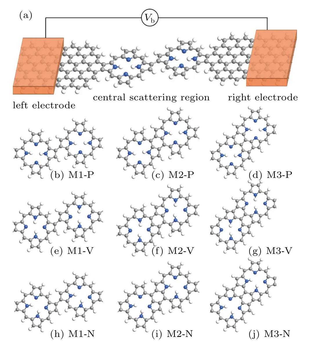
Fig.1.(a)The optimized structural geometry of the device.(b)–(j)The different molecular structures of the central scattering region:(b),(e),and(h)single C–C bond between the both porphine molecules,(c),(f),and(i)double C–C bonds link the two porphine molecules which form a five-membered ring configuration,(d),(g),and(j)three C–C link the two porphine molecules and formed two six membered rings.Here the P,V,and N represent the different positions of the hydrogen atoms:parallel transport direction(P),vertical transport direction(V),and the two hydrogen atoms bonding with neighboring nitrogen atoms(N),respectively.
3.Results and discussion
Firstly,we calculated the total energies of the all devices.The results show that M1-V,M2-V,M3-P have the lowest energies,respectively.The highest energies of these devices are M1-N,M2-N and M3-V,respectively.The total energy with respect to the lowest energy in each configuration is summarized in Table 1.We can see that the energy barrier between the P and T phases of M1 and M2 are low,which may lead to the conversion between the two phases.The energy barrier between different phases of M3 is very high.The energy barriers are much higher than the energy scale of thermal fluctuations in all cases.It means that the three states of M3 will be mechanically stable in the absence of external perturbations for the system.

Table 1.The energy difference between the different tautimers.Define the energy of each phase with the lowest energy to be zero.
To investigate the transport performance of these covalent homocoupling of porphine molecules after forming molecular devices,we calculate the current–voltage(I–V)curves of the all devices within the bias range[−0.6,0.6],as shown in Fig.2.On the whole,the current value of the M1 is the smallest under the same bias voltage,which is ten times smaller than that of the other two phases.M3 has the highest current value at the same bias.For the same coupling model,the current value of P phase is always greater than that of the T and N phases.Therefore,the covalent homocoupling of two porphine molecules forms two six-membered rings through three C–C bonds,where the hydrogen atoms at the core of the porphyrin molecule parallel transport direction(M3-P)has the best electron transport capability when it used as the transport channel of molecular devices.Moreover,the transport characteristics of M1 are obviously different from those of M2 and M3.At low bias range(±0.1 V),the current increases rapidly with increasing voltage.When the voltage is greater than±0.1 V,the current of M1-P begins to increase slowly,while that of the M1-V and M1-N decreases slightly,which shows a current-limiting effect.It indicates that the molecular device constructed by using single C–C bond between the both porphine molecules which the hydrogen atoms at the core of the porphyrin molecule not parallel transport direction has the potential to be applied of current limiter.
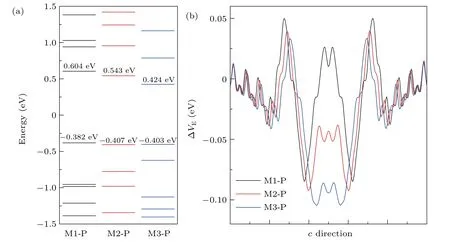
Fig.3.(a)The molecular energy spectrum and(b)electrostatic difference potential of the different covalent coupling of porphine molecules which the hydrogen atoms at the core of the porphyrin molecule parallel transport direction.
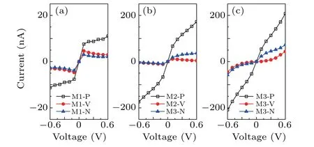
Fig.2.The I–V curves of the different devices.
To further understand the influence of different covalent coupling on transport of two porphine molecules atoms,we calculated the molecular orbital energy spectrum and the average electric potential energy,using the case of the hydrogen atoms at the core of the porphyrin molecule parallel transport direction as an example.As seen from Fig.3(a),we can find that the energy of the highest occupied molecular orbital(HOMO)for M1-P,M2-P and M3-P are almost the same.However,the energy of the lowest unoccupied molecular orbital(LUMO)for M3-P is closer to Fermi energy level than that of M1-P and M2-P.The biggest energy gap between the LUMO and HOMO is M1-P.The electron transition from HOMO to LUMO of M3-P requires the lowest energy.The electrons need much more energy from the HOMO to LUMO for M1-P.Therefore,the current of device M1-P is significantly lower than that of the other two devices.
In addition,the difference of current in three devices can be well explained by quantifying electrostatic differential potential energy,as shown in Fig.3(b).There is high potential barrier in both positions where the molecules are connected to the graphene electrodes.Obviously,M3-P has the lowest potential barrier,and with the highest potential energy is M1-P.This phenomenon is more obvious in the central scattering region.The electrostatic potential energy in the scattering region of M1-P is greater than zero,while that of M2-P and M3-P are less than zero.That means it is very difficult for M1 electrons to get from the left to the right electrode.Therefore,the current of M1-P is an order of magnitude smaller than that of the other two devices.
The local density of states(LDOS)and transmission pathways of the devices can also be used to understand the reason of the current difference of the devices.The LDOS D(E,r)is defined as

whereφi/j(r)andρij(E)are the atom centered basis orbital and the spectral density matrix,respectively.Localized or delocalized LDOS illustrated different properties.A localized LDOS indicates that the electron transport through the devices is obstructed,while the delocalized one means that a good electron transport channel is formed.The transmission pathways are an important index for analyzing electronic transport properties,which can visually reveal how the electron propagates from the left electrode to the right one.[44]The total transmission coefficient can be obtained as i

n which Tijis the local bond contributions.[45]If the system is divided into 2 parts(A,B),the total transmission coefficient is equal to the sum of the pathways across the boundary between A and B.Tijcan be both positive and negative,and the positive(negative)value correspond to that the electron is forward moving(back scattered)along the bond,i.e.,the direction of the arrows shows the flow of the electrons.
Comparing the LDOS of the three devices,as seen in Figs.4(a),4(c),and 4(e),one can clearly see that the electron distribution in the electrode are very similar.However,the distribution of the electrons in the central scattering region of the devices are quite different.The LDOS are localized for M1-P in the central scattering region,while those are generally delocalized over the whole central scattering region for M3-P.It indicates that the covalent homocoupling by three C–C bonds in two six-membered rings between the both porphine molecules has a much larger coupling with the electrodes than single C–C bond between the both porphine molecules.Figures 4(b),4(d),and 4(f)show the transmission pathways for the three devices at 0 V,where the volume of each arrow represents the magnitude of the local transmission between each pair of atoms.Here,the blue and red arrows represent the electron forward moving and back scattering,respectively.One can see that arrows dispersedly distributed on the whole scattering region of the three devices.But the distribution of arrows in the scatter region of the three devices are very different.Compared to the two devices,M1-P has a lot of red arrows in the locations where the two porphine molecules are connected.It means that the electron is reflected here,leading to the reduced total transmission.The main reason is that the device of M1-P has a high electrostatic potential barrier at this location[see Fig.3(b)].Whereas the potential barrier of M2-P and M3-P is less than zero.By comparing the distribution of arrows at the junction of molecules and electrodes of M2-P and M3-P,it can be found that the distribution of arrows in M3-P is more because M3-P has a lower barrier than M2-P[see Fig.3(b)].All of these can help to explain why the current value of M3-P is greater than that of M1-P.
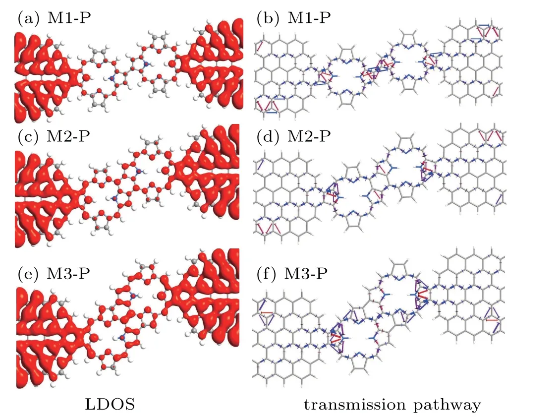
Fig.4.The LDOS and transmission pathway of the three devices in the fermi level at zero bias.The blue and red arrows indicate the electron forward moving and back scattering,respectively.
From Fig.2 we can also see that the position of the hydrogen atoms has a great influence on the current.Where the current value in the P configuration is the largest,and the current value in the V configuration is the smallest.We use the transmission spectrum and pathway at 0.5 V as examples to understand the current differences among the three configurations.It can be clearly seen that the value of transmission probability of the three devices is the maximum of M3-P and the minimum of M3-V in the bias window.We can know from the formula that the current value of M3-P is the largest,which can be verified from Fig.2(c).From the transmission pathway,as shown in Figs.5(b)–(d),it is obvious that when the hydrogen atoms at the core of the porphyrin molecule are perpendicular to the transmission direction(V configuration),it has a significant blocking effect on the electron transmission[see Fig.5(c)].The arrows representing the direction of electron movement are localized at the left electrode,which means it is extremely difficult for electrons from the left electrode to reach the right electrode.However,the arrows are distributed throughout the device in the P configuration.So the current in the P configuration of the device is much higher than that of the V configuration.
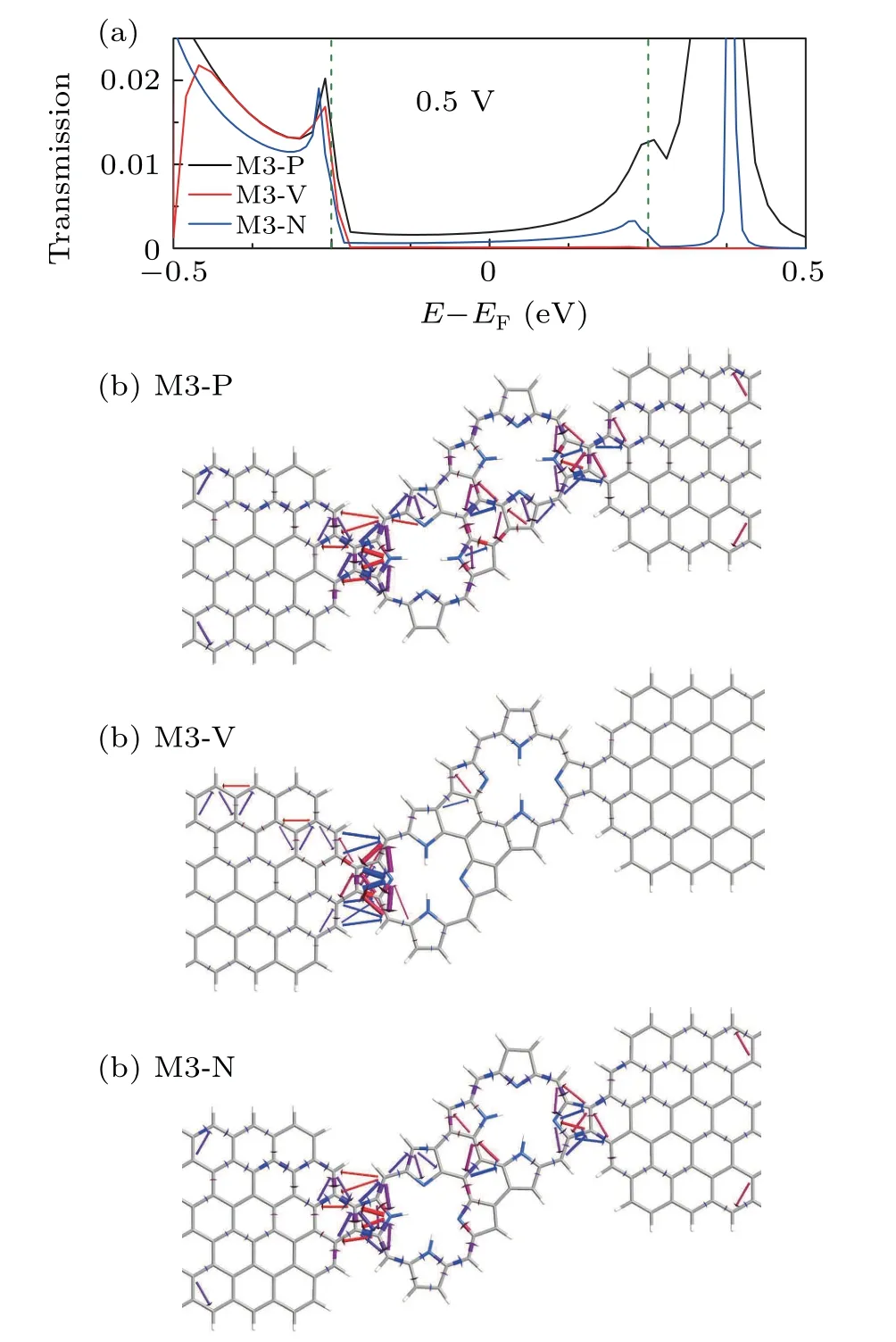
Fig.5.(a)Transmission probability as a function of energy for the device M3 of three configurations at 0.5 V.The green dashed lines indicate the range of the bias window.(b)–(d)The transmission pathways for the device M3 of three configurations at 0.5 V.
4.Summary and conclusion
In summary,we have investigated the transport properties for a junction of the covalent homocoupling of porphine molecules with different phases in conjunction with zigzag graphene electrodes.By using the DFT combined with NEGF formalism,we have shown that different coupling modes for porphine molecules have different transport properties,and the position of the hydrogen atoms within the porphyrin core can control the value of the current.The covalent homocoupling of porphine with three C–C bonds between two six-membered rings as the transport channel has better electron transport capacity than the others.While the covalent homocoupling of porphine with single C–C bond between the both porphine molecules has good potential to be applied of current limiter.The mechanism of the differential transport properties is analyzed and discussed in terms of the molecular energy spectrum,electrostatic difference potential,LODS,and transmission pathway.The results may make some contributions to develop and design molecular devices in which porphyrin molecules are covalently coupled.
- Chinese Physics B的其它文章
- Multiple solutions and hysteresis in the flows driven by surface with antisymmetric velocity profile∗
- Magnetization relaxation of uniaxial anisotropic ferromagnetic particles with linear reaction dynamics driven by DC/AC magnetic field∗
- Influences of spin–orbit interaction on quantum speed limit and entanglement of spin qubits in coupled quantum dots
- Quantum multicast schemes of different quantum states via non-maximally entangled channels with multiparty involvement∗
- Magnetic and electronic properties of two-dimensional metal-organic frameworks TM3(C2NH)12*
- Preparation of a two-state mixture of ultracold fermionic atoms with balanced population subject to the unstable magnetic field∗

