
Correspondence:Centrifuge model testing to ascertain vertical displacements of a pile under cyclic lateral loads*#
2021-09-21 03:45GangZHENGJibinSUNTianqiZHANGYangJIAOYuDIAO
Gang ZHENG, Ji-bin SUN, Tian-qi ZHANG, Yang JIAO, Yu DIAO
Correspondence:Centrifuge model testing to ascertain vertical displacements of a pile under cyclic lateral loads*#
Gang ZHENG, Ji-bin SUN, Tian-qi ZHANG†‡, Yang JIAO, Yu DIAO
†E-mail: tianqizhang@tju.edu.cn
Piles, as the basic components that support superstructures, are inevitably subjected to cyclic lateral loads. The lateral response (deformation and capacity) of a pile under a cyclic lateral load has been well documented. However, little attention has been given to its vertical d`isplacement. In this study, centrifuge model tests were conducted to study the vertical displacements of a pile under cyclic lateral loads. It was found that a pile may settle during cyclic lateral loading. Meanwhile, the ultimate settlement of the pile was larger when the vertical load or the amplitude of the horizontal displacement was greater. All the observations can be explained by the loss of mobilized shaft friction and the transmission of the unbalanced force to the pile tip.
1 Introduction
Due to their high stiffness and low construction cost, pile foundations have been extensively adopted in viaducts, high-rise buildings, and offshore infrastructures (Zhang et al., 2005; Kong DQ et al., 2019). As the basic components that support superstructures, piles are inevitably subjected to cyclic lateral loads (e.g. start and brake forces of vehicles acting on a viaduct, earthquake forces acting on a high-rise building, and wind or wave loads acting on an offshore wind turbine, as shown in Fig. 1). Although studies on laterally loaded piles have been well documented, most of these studies have focused on their lateral responses (deformation and capacity) (Reese et al., 1974; Meyerhof et al., 1981; Poulos et al., 1995; Leblanc et al., 2010; Randolph and Schneider, 2018; Kong LG et al., 2019), and scant attention has been given to their vertical displacements.
In this research,centrifuge model tests were performed to investigate the vertical displacements of a pile under cyclic lateral loads. As an initial exploration of the fundamental mechanism, all the tests were conducted in dry sand to exclude the interference of many complex factors, such as the liquefaction of wet sands and seismic subsidence of soft clays. By using “digital image correlation” (DIC) technology, the vertical displacements of the pile were obtained and analyzed. Based on the test results, the mechanism by which the pile moves along the vertical direction under cyclic lateral loads is discussed and clarified.
2 Centrifuge model tests
2.1 Test apparatus
The centrifuge model tests were conducted in a strong box at 100(is the gravitational acceleration) at Tianjin University, China. The strong box was made of a steel frame and three fibre-reinforced plastic plates. The plates were transparent so that the movements of the pile could be observed from outside the box. A high-speed camera, which was fixed outside the box as shown in Fig. 2a, was adopted to record the movement of the pile under cyclic lateral loads. The inner dimensions of the box were approximately 200 mm long, 140 mm wide, and 300 mm high. The ratio of the strong box length to the pile diameter (6 mm) was larger than 10, so boundary effects were deemed to be negligible (Chen and Poulos, 1993).
In the tests, a self-designed loading system was used to apply a two-way cyclic lateral load to the model pile, as shown in Fig. 2b. In this system, a servo-actuator was used to provide torque to drive the rotation of the lead screw through the conveyor. Then, the lead screw drove the sliding block to move along the horizontal guide rail and subsequently to apply the cyclic lateral load on the pile. In this study, cyclic lateral loads were applied based on the displacement- controlled method, which could be characterized by the amplitude of the horizontal displacement,, of the pile at point, as shown in Fig. 3.
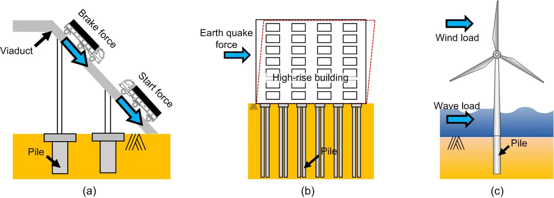
Fig. 1 Piles work under cyclic lateral loads
(a) Viaduct; (b) High-rise building; (c) Offshore wind turbine
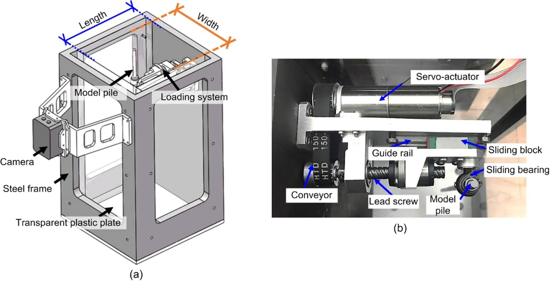
Fig. 2 Experimental apparatus
(a) Strong box; (b) Loading system
The pile was sleeved into a sliding bearing which could freely rotate. The friction coefficient between the pile and the sliding bearing was approximately 3‰. Thus, the influence of friction on the vertical displacement of the pile was deemed to be negligible.
Titanium alloy was used for the fabrication of the main body of the pile, and the surface of the pile was coated with steel. The external diameter of the pile,, was 6 mm, the length,, was 200 mm, and the mass was 20 g. The pile bottom was flat and closed-ended, and an axial load transducer was wielded on the pile tip to monitor the load acting on the tip of the pile. The top of the pile was threaded so that standard dead weights (20 g, 40 g, and 60 g) could be fixed on the top of the model pile to apply a vertical load (20 N, 40 N, and 60 N under 100conditions, respectively). As shown in Fig. 3, the side surface of the pile was marked with black solid lines at 5-mm intervals so that the movements of the pile could be traced during the tests.
The soil used in the tests was Toyoura sand. The mean particle diameter,50, of Toyoura sand was 0.16 mm, and the specific gravity of the particles,s, was 2.65. Because the ratio of the model pile diameter to the mean particle diameter was larger than the limiting value of 20 suggested by Gui et al. (1998), grain-size scaling effects could be neglected. In this study, the void ratio of the sample measured before the test begun was about 0.74. The maximum and minimum void ratios were 1.04 and 0.597 (Ishihara, 1993), respectively.
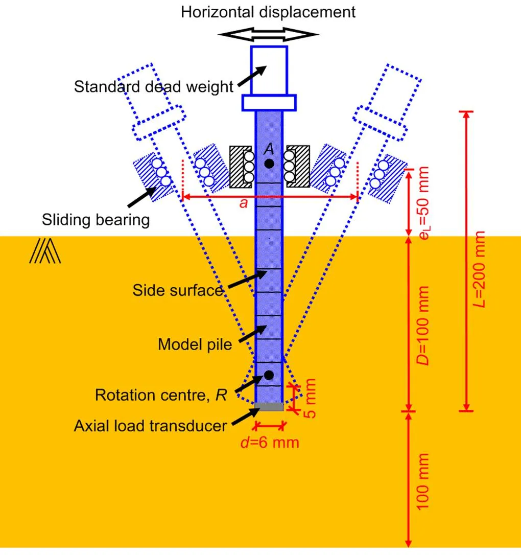
Fig. 3 Sketch of the loading process
L: eccentricity of the lateral load;: pile depth
2.2 Test program
During the preparation stage of the tests, the model pile and the sand were both pre-set in the experimental system at 1condition. First, the model pile was inserted through the sliding bearing and fixed at the predesigned position with a specially designed clip. After the model pile was fixed firmly with the sliding bearing, the pile could not move vertically, and the sliding bearing could not rotate until the clip was uninstalled. Then, the high-speed camera was mounted on the frames of the strong box.
The sand sample in the test was prepared by the pluviation method. To achieve a relatively loose state for the sand, a drop heightof 10 mm was adopted. Soil pouring stopped when the soil surface reached the predesigned position. Then, the surface of the soil was slightly scraped to ensure that the depth of the soil was 200 mm and that the surface of the soil was flat. Then, the whole strong box was fixed on the basket of the centrifuge.
Before the centrifuge was spun up, the clip was uninstalled, and the camera was set on high-speed mode. Then, the centrifuge was spun up to 100slowly in 5 min and the test begun. In this study, 5000 cycles of the lateral loads were applied to the model pile in each test.
Seven centrifuge model tests in total were performed in this study. In these tests, the pile depth,, was 100 mm. The eccentricity of the lateral load,L, was 50 mm (Fig. 3). The vertical load,v, and the amplitude of horizontal displacement,, were treated as variables. The detail of the tests is shown in Table 1.
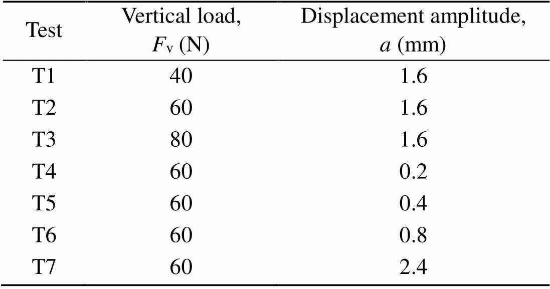
Table 1 Test information
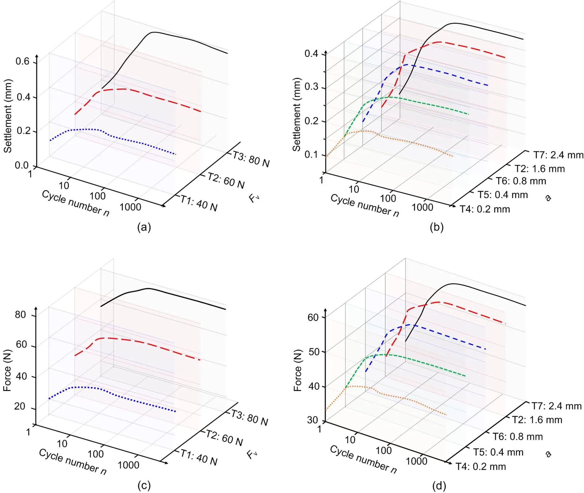
Fig. 4 Test results
(a) Settlements of piles in tests T1–T3; (b) Settlements of piles in tests T2 and T4–T7; (c) Variations of loads measured at the pile tip in tests T1–T3; (d) Variations of loads measured at the pile tip in tests T2 and T4–T7
3 Test results
The results of the tests are summarized in Fig. 4. To demonstrate the curves more clearly, all the curves are presented in logarithmic coordinates.
Figs. 4a and 4b show the settlements of the pile with different vertical loads,v, and different amplitudes of the horizontal displacements,, respectively. From Figs. 4a and 4b, three phenomena could be concluded as follows: (a) in all the tests, under a cyclic lateral load, a pile would settle finitely; (b) in Fig. 4a, the ultimate settlement of the pile was more significant when the vertical loadvwas larger; (c) in Fig. 4b, the ultimate settlement of the pile was more significant when the amplitude of horizontal displacementwas larger.
In Figs. 4c and 4d, the variations in the loads acting on the pile tip are presented. They were measured by the axial load transducer welded on the pile tip. In tests T1–T3, the initial and ultimate loads that acted on the pile tip were larger for the pile with largerv. In tests T2 and T4–T7, the initial loads that acted on the pile tip were the same, but the ultimate loads were larger for the pile with larger.
4 Mechanism behind the settlement of the pile
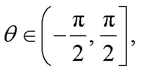
For the ease of clear interpretation, we introduce the definitions of the “front side” and “back side” of a pile in this study. As shown in Fig. 5, in which the cross section of the pile at depthwas taken as an example, on the front side, the anglebetween the outward normal vector,, and the direction vector of the movement of the pile,, satisfies
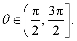
and on the back side, the anglebetweenandsatisfies
It should be noted that the front side and back side of the cross section of the pile, at a certain depth, switch with the reciprocal movement of the pile. The moving directions of the pile above and below the rotation centre,, as marked in Fig. 3, at which no displacement is anticipated (Guo, 2008), were opposite. Accordingly, the front and back sides of the sections at depths above and below the rotation centre were also opposite.
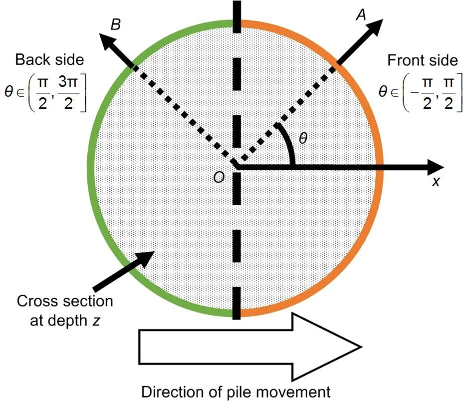
Fig. 5 “Back side” and “front side”
As the pile moved rightwards, as shown in Fig. 6b, the pressure acting on the back side decreased ton1-backand oppositely on the front side increased ton1-front. The limit shaft friction on the back side of the pile,back-limit,1, decreased due to the reduction of the pressuren1-back, and could be calculated according to the integration ofn1-backin the areas of the back side.
Ifback-limit,1was larger than0, the mobilized shaft friction would remain unchanged and equal0. However, if theback-limit,1was less than0, the shaft friction of the back side would decrease from0toback-limit,1, because the soil could not afford0to the pile at the pile-soil interface. In this case, an unbalanced force, Δ1, would be generated, which was the difference betweenback-limit,1and0.
The unbalanced force Δ1, would be transmitted to the front side and the tip of the pile, according to the ratio between the stiffnesses, against vertical displacements, of the pile tip and the front side. With the known forces that were transmitted to the pile tip and the stiffness of the pile tip, the settlement of the pile in this movement could be obtained.
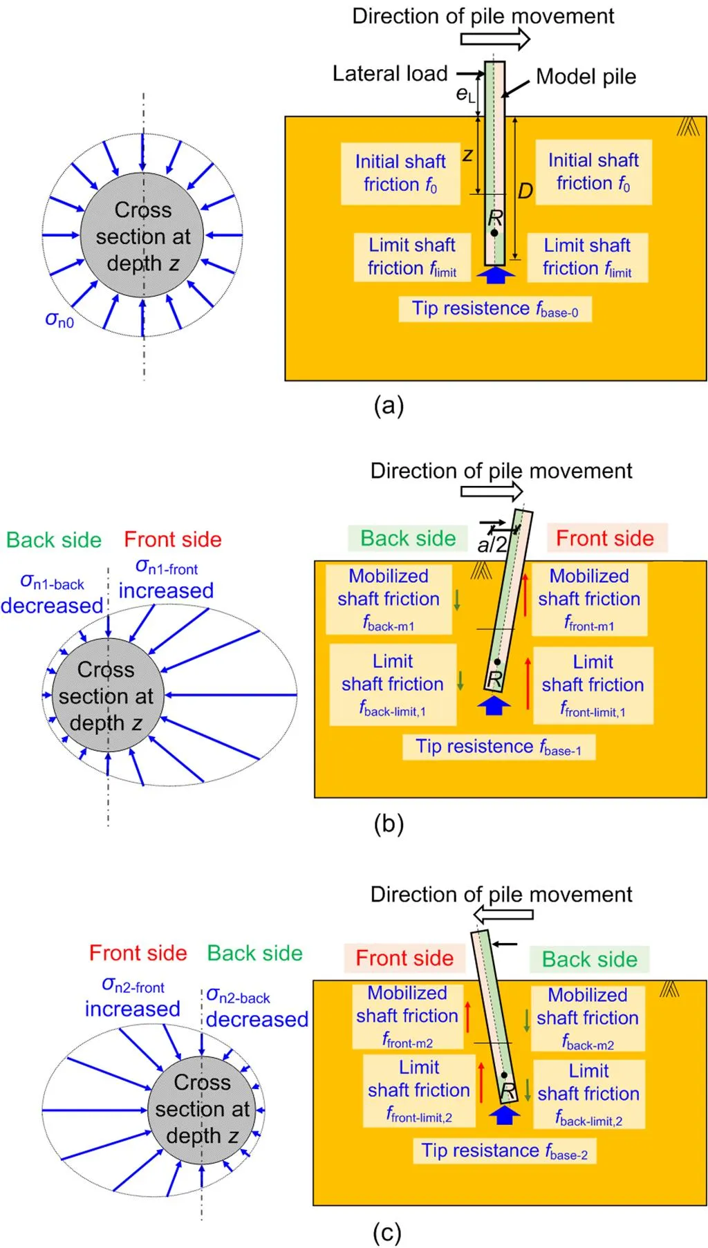
Fig. 6 Sketch of the pile settlement mechanism
(a) Initial state of the pile; (b) Working state of pile after the first movement (rightwards); (c) Working state of pile after the second movement (leftwards). For more details please refer to Data S1 of the electronic supplementary materials
In the second movement, the pile moved leftwards as shown in Fig. 6c, the variations in the pressures acting on the pile were similar to those in the first movement, but the front side and back side switched. The unbalanced force, Δ2, generated in the second movement, was the difference between the limit shaft friction of the back side at the end of the second movement and the mobilized shaft friction of the same side at the end of the previous movement. Similarly, Δ2, would be transmitted to the pile tip and the front side, following which the pile settled.
Aftercycles in total, the ultimate settlement of the pile was the summation of all the sub-settlements of the pile in each movement.
The above analysis indicated that, under cyclic lateral loads, the unbalanced forces would be gradually transmitted to the pile tip. This has been verified by the variations in the measured forces acting on the pile tip (Fig. 4c). After sufficiently large numbers of cycles, when the mobilized shaft friction of the pile had decreased to a value that was almost equivalent to the limit shaft friction on the back side of the pile, the unbalanced force would be negligible, and the settlement of the pile might cease to develop. That was why the pile would settle but not infinitely under cyclic lateral loads. Of course, if the initial shaft friction of the pile were very small, the mobilized shaft friction on the back side of the pile would always be smaller than the limit shaft friction on the back side of the pile during the cyclic lateral loading, and the pile might not settle. Apparently, that did not occur in any of the tests presented in this study.
5 Conclusions
This paper describes centrifuge model tests for studying the vertical displacement of a pile under cyclic lateral loads. Based on the test results, the following conclusions can be drawn:
1. Under a cyclic lateral load, the pile may settle due to the loss of shaft friction. The ultimate settlement of the pile is larger when the vertical load or the amplitude of the horizontal displacement is greater.
2. The settlements of the pile could be attributed to the loss of the mobilized shaft friction on the back side of the pile and the transmission of the unbalanced force to the pile tip. This was verified from the measured forces acting on the pile tip (Fig. 4c).
3. It was deduced that the end-bearing piles would have advantages over friction piles under cyclic lateral loads, considering the effect of the potential loss of the shaft friction of the pile.
Based on the mechanisms that were discussed in this study, a theoretical model could be proposed to calculate the settlement of a pile under cyclic lateral loads under the framework of the load-transfer method (Li et al., 2012). However, due to the limited space, this was not included in this study and will be presented in a forthcoming paper.
Contributors
Gang ZHENG and Tian-qi ZHANG designed the research. Tian-qi ZHANG and Ji-bin SUN wrote the first draft of the manuscript. Yang JIAO processed the test data. Tian-qi ZHANG, Ji-bin SUN, and Yu DIAO revised and edited the final version.
Conflict of interest
Gang ZHENG, Ji-bin SUN, Tian-qi ZHANG, Yang JIAO, and Yu DIAO declare that they have no conflict of interest.
List of electronic supplementary materials
Data S1 Simple computational model
Chen L, Poulos HG, 1993. Analysis of pile-soil interaction under lateral loading using infinite and finite elements., 15(4):189-220. https://doi.org/10.1016/0266-352X(93)90001-N
Gui MW, Bolton MD, Garnier J, et al., 1998. Guidelines for cone penetration tests in sand. Proceedings of the International Conference on Centrifuge Modelling (Centrifuge’98), p.155-160.
Guo WD, 2008. Laterally loaded rigid piles in cohesionless soil., 45(5):676-697. https://doi.org/10.1139/T07-110
Ishihara K, 1993. Liquefaction and flow failure during earthquakes., 43(3):351-415. https://doi.org/10.1680/geot.1993.43.3.351
Kong DQ, Wen K, Zhu B, et al., 2019. Centrifuge modeling of cyclic lateral behaviors of a tetrapod piled jacket foundation for offshore wind turbines in sand., 145(11):04019099-1-13. https://doi.org/10.1061/(asce)gt.1943-5606.0002160
Kong LG, Fan JY, LiuJW, et al., 2019. Group effect in piles undereccentric lateral loading in sand., 20(4):243-257. https://doi.org/10.1631/jzus.A1800617
Leblanc C, Houlsby GT, Byrne BW, 2010. Response of stiff piles in sand to long-term cyclic lateral loading., 60(2):79-90. https://doi.org/10.1680/geot.7.00196
Li MZ, Bolton MD, Haigh SK, 2012. Cyclic axial behaviour of piles and pile groups in sand., 49(9):1074-1087. https://doi.org/10.1139/t2012-070
Meyerhof GG, Mathur SK, Valsangkar AJ, 1981. Lateral resistance and deflection of rigid walls and piles in layered soils., 18(2):159-170. https://doi.org/10.1139/t81-021
Poulos HG, Chen LT, Hull TS, 1995.Model tests on single piles subjected to lateral soil movement., 35(4):85-92. https://doi.org/10.3208/sandf.35.4_85
Randolph M, Schneider J, 2018. Pile foundations: design for axial and lateral loading.: Carlton J, Jukes P, Choo YS (Eds.), Encyclopedia of Maritime and Offshore EngineeringJohn Wiley & Sons, Hoboken, USA. https://doi.org/10.1002/9781118476406.emoe533
Reese LC, Cox WR, Koop FD, 1974. Analysis of laterally loaded piles in sand. Proceedings of the Offshore Technology Conference, p.473-483. https://doi.org/10.4043/2080-MS
Zhang LY, Silva F, Grismala R, 2005. Ultimate lateral resistance to piles in cohesionless soils.,131(1):78-83. https://doi.org/10.1061/(asce)1090-0241(2005)131:1(78)
Journal of Zhejiang University-SCIENCE A (Applied Physics & Engineering)
ISSN 1673-565X (Print); ISSN 1862-1775 (Online)
www.jzus.zju.edu.cn; link.springer.com
E-mail: jzus_a@zju.edu.cn
https://doi.org/10.1631/jzus.A2000477
# Electronic supplementary materials: The online version of this article (https://doi.org/10.1631/jzus.A2000477) contains supplementary materials, which are available to authorized users
© Zhejiang University Press 2021
*Project supported by the National Natural Science Foundation of China (Nos. 41630641 and 51808387)
 Journal of Zhejiang University-Science A(Applied Physics & Engineering)2021年9期
- Journal of Zhejiang University-Science A(Applied Physics & Engineering)的其它文章
- Wave filtering and firing modes in a light-sensitive neural circuit*
- Dynamic response analysis of airport pavements during aircraft taxiing for evaluating pavement bearing capacity*
- Compressive behavior of hybrid steel-polyvinyl alcohol fiber-reinforced concrete containing fly ash and slag powder: experiments and an artificial neural network model*#
- A method to avoid the cycle-skip phenomenon in time-of-flight determination for ultrasonic flow measurement*
- Carbon self-doped polytriazine imide nanotubes with optimized electronic structure for enhanced photocatalytic activity*#