A robust model-free controller for a three-phase grid-connected photovoltaic system based on ultra-local model
Ahsene Boubakir, Sid‑Ahmed Touil, Salim Labiod and Nasserdine Boudjerda
Abstract In this paper, a robust model‑free controller for a grid‑connected photovoltaic (PV) system is designed.The system consists of a PV generator connected to a three‑phase grid by a DC/AC converter.The control objectives of the overall system are to extract maximum power from the PV source, to control reactive power exchange and to improve the quality of the current injected into the grid.The model‑free control technique is based on the use of an ultra‑local model instead of the dynamic model of the overall system.The local model is continuously updated based on a numerical differentiator using only the input–output behavior of the controlled system.The model‑free controller consists of a classical feedback controller and a compensator for the effects of internal parameter changes and exter‑nal disturbances.Simulation results illustrate the efficiency of the controller for grid‑connected PV systems.
Keywords: Photovoltaic system, Maximum power point, Model‑free control, Ultra‑local model, Numerical differentiator
1 Introduction
Solar energy is considered as one of the best sources of renewable energy to address the energy crisis and to reduce the level of pollution caused by the use of fossil fuels.Photovoltaic (PV) generator systems are used to directly and efficiently convert solar energy to electricity at low cost and can be classified as autonomous or standalone systems [1–3] and grid connected systems [4–6].They have been used primarily as stand-alone systems in locations where utility lines are not available, such as in mountains, islands and isolated sites, or in areas where installing utility lines is not economical.A stand-alone system requires batteries to store the energy supplied by the solar panels, so the batteries must be properly sized to obtain maximum efficiency from the PV generators.This increases the volume and cost of such installations[1, 2].Unlike autonomous systems, grid-connected PV systems allow direct injection of energy produced by solar panels into the grid [4, 5].
The overall efficiency of grid-connected PV systems is influenced by climatic factors such as solar radiation and temperature, as well as the converters and controllers being used.Since the weather factors are out of users’control, the choice of converter and controller design plays a key role in the performance of the overall system.The role of a power converter in a grid-connected PV system is to perform the energy transfer between the PV panels and the electrical grid.There are generally two main topologies depending on the number and type of the converters used [4, 5].In the first, referred to as double stage PV systems, the grid and the PV panels are connected via a DC/DC power converter, functioning as a maximal power point tracker (MPPT), and a DC/AC converter used for feeding power back to the grid and power factor correction (PFC).The second is the single stage PV systems [4], in which the grid and the PV panels are directly connected by a DC/AC converter providing MPPT, power transfer, and PFC requirements.
The efficient use of PV energy has attracted a lot of attention in the fields of renewable energy, electrical engineering, control engineering etc.The main control objectives in a grid-connected PV system are: i) feeding the extracted maximum power from the PV generator to the grid under various environmental conditions, ii) control of reactive power injected into the grid, and iii) minimization of the harmonic distortion in the current fed to the grid.
Design of control techniques for grid-connected PV systems has been much studied over the past years and remains an active area of research.Traditional fixed-gain linear controllers such as PI/PID controllers [7, 8] and repetitive controllers (RC) [9] have been widely used,while recent advances in control theory have enabled the development of other more effective control algorithms.In [4], an input output feedback linearization control scheme is proposed, one transforms the overall dynamics of the grid-connected PV system into two equivalent linear subsystems, to allow the use of the pole placement linear control technique.A robust feedback linearizing control strategy is suggested in [5] based on a sliding mode compensator to enhance robustness against uncertainties.In [10], a robust model predictive control is proposed to control a grid-connected PV system using a disturbance compensator with an integral action,while another robust control method is introduced in[11] consisting of an active disturbance rejection control law combined with an RC term and designed by solving linear matrix inequality constraints.In [12], an offset-free feedback linearization controller based on a PI/almost PID disturbance observer is presented.Other control strategies can also be found in the literature such as second-order sliding model [13, 14], fuzzy logic[15–17], robust [18, 19], the backstepping technique [6,20] and predictive [21, 22].The majority of control laws proposed in the aforementioned works and other literature are either fixed-gain linear [7, 8], model-based [4, 5,10], or control methods based on artificial intelligence tools such as fuzzy logic or neural networks [15–17, 23].Unfortunately, a conventional fixed-gain linear controller cannot efficiently handle dynamic operating conditions or cope with external disturbances.In addition, the performance of a model-based controller is highly dependent on obtaining a good dynamic model of the system and its operating environment along with knowledge of the external disturbances that influence its behavior.It is usually difficult to meet these needs.Although the learning capacities of artificial intelligence tools help in the approximation of uncertainties, they complicate the structure of the control laws and their real-time implementation.In addition, the closed-loop performance of a controller based on artificial intelligence tools depend upon designer skills.
In this work, a Model-Free Controller (MFC) based on an elementary continuously updated local model is designed for a grid-connected PV system.An ultralocal model valid over a short period of time is used to instantly identify the overall system dynamics, while the adopted local model is continuously updated using only the input–output behavior of the system with an online numerical differentiator.The derived control law consists of a classical feedback controller and a compensator which compensates for the effects of internal parameter changes and external disturbances.The model-free control approach proposed presents a more effective solution in grid-connected PV system control than previously cited control methods.It offers users a universal and robust controller that easily adapts to the external environment and its changes.The key advantages of the proposed control and the contributions of the paper include:
1.Unlike the majority of existing approaches, the proposed control scheme can control the power factor and the DC-link voltage with the same control algorithm.Thus there is no need to carry out the control of these variables with two separate algorithms.
2.The MPP tracking is achieved by controlling the DC/AC converter.This eliminates the need for a DC-DC converter.
3.The control law is derived directly from a general model of grid-connected PV systems and its implementation does not require knowledge of the model.This means that the designed controller can be regarded as a universal model-free controller for grid-connected PV systems.
4.The instantaneous identification of the overall dynamics significantly improves the robustness of the MFC controller against internal parameter changes(e.g., filter parameters or grid electrical quantities)and external disturbances (e.g., atmospheric conditions).
5.In contrast to the existing model-free controls of grid-connected PV systems such as the conventional fixed-gain linear controllers and methods based on artificial intelligence tools (e.g., fuzzy logic, neural networks or optimization techniques), the proposed model-free control is easy to implement, robust and self-adjusting.
The rest of this paper is organized as follows.Section 2 gives the description and mathematical modeling of the grid-connected PV system.The principle of the model-free control technique based on instantaneous identification is introduced in Sect.3, while model-free control design for the grid-connected PV system and the analysis of the simulation results are detailed in Sect.4.Finally, Sect.5 concludes the paper.
2 Description and modeling of the grid‑connected PV system
The structure of the grid-connected PV system is displayed in Fig.1.It includes a PV generator, a DC-link capacitor, and a three-phase two-level converter connected to the grid via an inductive output filter.The role of the DC-link capacitor in this single-stage configuration is to maintain the voltage at the input of the converter within an acceptable operating range.The converter, with its control mechanism, regulates the DC-link voltage to a desired level and synchronizes the converter output current with the grid voltage to achieve unity power factor.The filter enhances the quality of the current injected into the grid by reducing harmonic pollution.

Fig.1 Schematic diagram of the grid‑connected PV system
To facilitate the design of the system controller, a detailed mathematical representation of all the parts of the system is derived.It is worth noting that for the proposed control scheme, the knowledge of the system model is not required for its real-time implementation as it is in conventional model-based controllers.
2.1 PV array modeling
PV cells are the basic components of all PV generator systems.A PV cell is a p–n junction able to convert sunlight directly to electric power.The equivalent circuit of a PV cell is shown in Fig.2.It is composed of a light generated current source in parallel with a diode, a series resistance Rsand a shunt resistance Rshthat characterize respectively the series connecting circuit and the losses in the PV cell as parallel current leakage.A single PV cell can only provide a small amount of energy, so a number of cells are assembled in series–parallel combination to make a PV module with higher current and voltage.A PV generator is constituted of PV modules connected in series and in parallel to obtain the desired output power.
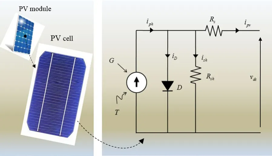
Fig.2 Equivalent circuit of a PV cell
From the equivalent circuit in Fig.2, there is:

where iphis the photocurrent whose intensity depends on irradiance G and temperature T , iDis the current through the diode and ishis the current flowing through the resistor Rsh.
The relationship between the output current ipvand voltage vdcfor a PV cell can be detailed as [1, 19, 24, 25]:

where I0is the cell reverse saturation current that depends on temperature T , q is the electron chargen is the quality factor of the diode, K is the Boltzman’s constant K =1.38×10⁻²³J/K and T is the cell temperature.
Note that the shunt resistance Rshin the equivalent circuit is large and its effect can be neglected in (2), as it only affects very low levels of solar irradiation [25].The output current ipvand voltage vdcof a PV module/array,that includes Nsseries cells and Npparallel cells, can be deduced from (2) as [1, 4, 25]:

where iscis the short circuit current at reference temperature Trefand radiation, and I0Ris the cell reverse saturation current at the reference temperature.kiis the short circuit current temperature coefficient, G is the total solar radiation in W/m2and Egis the band gap of the semiconductor used in the cell.
The selection of solar panels for PV generator systems is generally done according to the type of PV cells used and their efficiencies, short circuit current, open circuit voltage, optimal operating point and fill factor.The PV array size is designed based on the power requirement of the grid, and consists of strings of PV modules in series and in parallel.In this study, the BP3160 module [18, 26, 27] is chosen and is made of 72 multi-crystalline silicon solar cells connected in series and is able to provide 160 watts of nominal maximum power.The parameters of the BP3160 module in standard conditions ( 1 kW/m2and 25 °C) are shown in Table 1, and the I–V and P–V characteristics for different levels of solar radiation and temperature can be found in [18].The PV generator system here has 5 strings, each containing 30 PV modules.
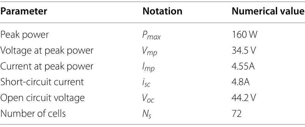
Table 1 Specifications of PV module BP3160 [26]
2.2 Three‑phase grid‑connected PV system modelling
In the following, the mathematical modeling of the dynamics of the three-phase grid-connected PV system is presented, and is composed of a PV module, a capacitive DC-link, a three-phase two-level converter and a three-phase grid with inductive output filter.First, the dynamic equations of the grid current are written as:
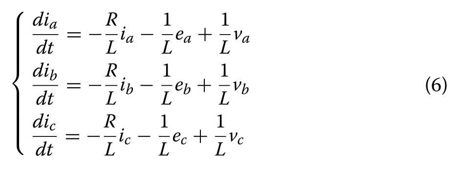
where va, vband vcare the three-phase voltages at the output of the converter, ia, iband icrepresent the threephase currents injected into the grid, ea, eband ecare the three-phase grid voltages, and R and L are the total resistance and inductance of the line filter.Considering uncertainties, the dynamics of the three-phase converter can be represented in the dq rotating reference frame as:

where idand iqare the respective d-axis and q-axis currents, vdand vqdenote the d-axis and q-axis components of the converter output voltage, edand eqare the d-axis and q-axis components of the grid voltage, respectively.w =2πf where f is the grid frequency, and ϕdand ϕqdenote the disturbance terms such as unmodeled dynamics and exogenous disturbances.
The DC side of the converter is governed by the following dynamics equation:

where vdcis the DC-link voltage, idcis the DC input current to the converter, ipvis the PV array output current and C is the DC-link capacitance.When the power losses in the electronic switches are neglected, the power balance relationship between the input and output of the converter can be expressed as:

Substituting idcin (8) by its expression derived from(9) yields:

Considering the system uncertainties, (10) can be rewritten as:

where ϕvrepresents the system uncertainties and external disturbances.
Finally, the overall dynamics of the controlled system are given by:
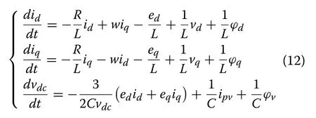
In the dq rotating reference frame, the active and reactive powers, P and Q , injected into the grid can be described by [13, 17]:

Assuming that the rotation of the dq reference frame is synchronized with the grid voltage vector [13], i.e.,e=ed+j0 , then (13) becomes:

From (14), it is possible to minimize the reactive power Q by forcing the q − axis line current iqto zero.
In the next section, the basic principles of the modelfree control technique and the different structures of the intelligent PID controller will be presented.
3 Model‑free control technique
Over the last decade, the design of model-free control schemes based on a continuously updated local model,and the so-called intelligent PID controllers or i-PID, has been an active area of research, because of the importance of these controllers in industrial control systems[28–30].The main idea is to control a given unknown plant as a simple linear system of order υ .This is a local nonphysical model and the so-called ultra-local model.It represents an instantaneous identification of the overall dynamics of the controlled system.
3.1 Ultra‑local model
The input–output behavior of a controlled plant, even if it is highly nonlinear and time-varying, can be well approximated within its operating range by an unknown finitedimensional ordinary differential equation in the form of:

where u and y are the input and output variables of the system, E is assumed to be a sufficiently regular function of its arguments, while a and b are the derivative orders of output y and input u , respectively.
Now, suppose that for an integer υ , 0<υ ≤a , there isThus, according to the implicit function theorem [31, 32], the system in (15) can locally be rewritten as:

The principle of the model-free control method (as shown in Fig.3), proposed by Fliess et al.[28, 29], is to replace (16) by a phenomenological ultra-local model which is valid only during a very short time interval, as:
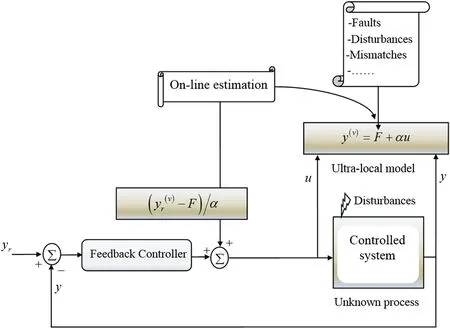
Fig.3 Principle of the model‑free control method

where F includes the unmodeled system dynamics, the parametric uncertainty and the external disturbances.α ∈R is a non-physical constant parameter.Users can choose the value of α by trial and error such that F and αu are of the same magnitude.
Remark 1The order of derivative υ in (17) is not necessarily equal to the order of derivative a of output y in (16).Usually, the design parameter υ is selected as υ =1 or 2 independently of the system order [29, 30].In addition,according to (17), knowledge of only y(υ), u and α is sufficient to determine the value of F at each instant of time.
For control purposes, the term F in (17) is assumed to be a piecewise constant function and its estimate is denoted as, which is continuously updated as:

3.2 Principle and structure of model‑free control
To force the output y of a controlled plant, as in (15) and(17), to follow a given smooth reference trajectory yr, the input u can be designed as:

with e=yr−y as the tracking error.(e) is a function that should be selected so that the desired closed-loop behavior e(υ)+ (e)=0 is asymptotically stable, where (e)=Kυ−1e(υ−1)+···+K1+K0e .In fact, the term (e) in (19) represents a classical feedback controller,chosen by the operator, and the componentis for cancelling the influence of the unmodeled system dynamics and the external disturbances.
The substitution of (19) in (17) gives the following for the tracking error e:

Therefore, a model-free controller in the form (19) can ensure the asymptotic stability of the closed-loop system if F is well estimated such that F −≈0.
3.3 Intelligent‑PID controllers
Several control methods can be used in (19) to design the feedback controller ufeedback= (e) .This is connected to the model-free nonlinearity compensator, i.e.,to form the model-free control law.Generally, the PID controller is the one most used as a feedback controller because of its simple structure and ease of implementation.A model-free control law in the form (19) with a PID feedback controller is called intelligent PID or i-PID.
When selecting the order of derivative υ =2 in (17),the control objective can be achieved by the intelligent controllers i-PID or i-PD given by:
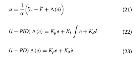
where Kp, KIand Kddenote the proportional, derivative and integral gains, respectively.On the other hand,an intelligent Proportional Integral (i-PI) controller or an intelligent Proportional (i-P) controller can be designed when υ =1 in (17), such that:

Remark 2The i-P and i-PD controllers are the two most widely used intelligent controllers in control system applications.In the light of the study in [33], the i-P and i-PD controllers are very efficient, unlike i-PI and i-PID controllers which play an imaginary role.Moreover, a certain equivalence exists between i-PD and the usual PID as demonstrated in [29, 34].Hence, the i-PD controller is suggested as a good replacement for the conventional PID controller.
3.4 Algebraic estimation of F
Remark 3It is worth pointing out that the previous control inputs are used to compute the estimatein (18)in order to avoid any algebraic loop.Thereby,can be computed as:

where u(t −h) is delayed control while the delay h is sufficiently small and whose value can be chosen equal to one or a few sampling instants.
4 Model‑free control applied to the grid‑connected PV system
The purpose of this part of the paper is to apply and verify the efficiency of the model-free control technique discussed in the previous section for a grid-connected PV system.A comparative study with conventional controllers is carried out to highlight the performance of the developed controller.A model-free controller is designed for the grid-connected PV system based on ultra-local models derived from the overall dynamic model of the system, which contains uncertainties and is subjected to external disturbances.
4.1 Control objectives
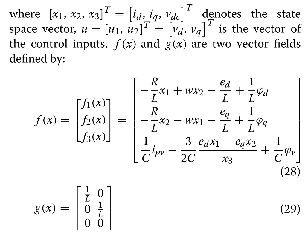
The control objectives for the grid-connected PV system are to extract the maximum power from the PV generator system regardless of atmospheric conditions, to control the reactive power injected into the grid and to improve the quality of the grid current.For this system, the maximum power extraction can be achieved by forcing the DC-link voltage vdcto follow its reference computed by the MPPT tracker, while the control of the reactive power injected into the grid can be fulfilled by controlling iqof the grid current.Hence, y1=vdcand y2=iqare selected as the controlled outputs for the system.
The state representation of (12) can be expressed as:

4.2 Ultra‑local model of the grid‑connected PV system
To obtain the input–output form of the system (27),the two outputs y1=vdcand y2=iqare differentiated repeatedly until at least one input u1or u2appears explicitly in the expression of derivatives.This results in:

where f1, f2and f3are given in (28).
The main limitation of controlling (30) using a modelbased control technique is the need for the knowledge of the system parameters and disturbances that influence its behavior, as it is not easy to precisely identify the system uncertainties, external disturbances or electrical parameters or quantities.Moreover, the system parameters and the disturbances acting on the process can change during operation.This complicates practical implementation of a model-based controller and can significantly reduce control performance.Thus, in order to address these issues, the dynamic model (30) is replaced by the following ultra-local model, as:

where F1and F2include the unmodeled system dynamics, parametric uncertainty and external disturbances.αij∈R , i=1, 2 and j =1, 2 , are design parameters to be selected by users.Both F1and F2are continuously updated to achieve a good estimation of the system dynamics and external disturbances.These estimates are valid for a short period of time and are considered within the closed-loop controller.
4.3 Controller design
The nonphysical model (31) is used here to design a MFC controller for the grid-connected PV system.The control law consists of two components: the first is a classical feedback controller and the second is a compensator for the effects of unmodeled system dynamics and external disturbances.Equation (31) can be rewritten in the following compact form, as:

where y=[y1, y2]Tdenotes the output vector,u=[u1, u2]Tis the control input vector, F =[F1, F2]Trepresents the unmodeled system dynamics, and D is the control gain matrix given by:

Defining the tracking errors by e1=yr1−y1and e2 =yr2−y2, or e1=vdcr−vdcand e2=iqr−iqwhere vdcris generated by the MPPT tracker, the control objectives for the system (27) can be fulfilled with the following model-free control law:
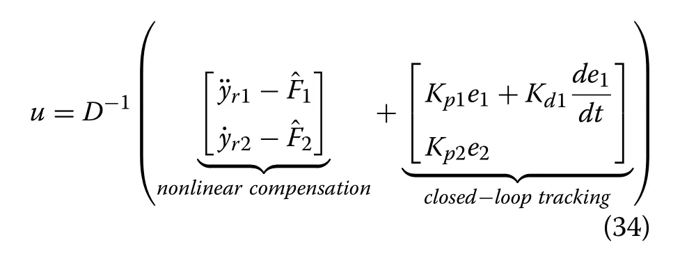
Thus, the control input signals u1and u2can be regarded as the outputs of the i-PD and i-P controllers.Kp1and Kp2, and Kd1in (34) denote the proportional and the derivative gains, respectively.andin the nonlinearity compensator are the estimates of F1and F2, and are computed as:

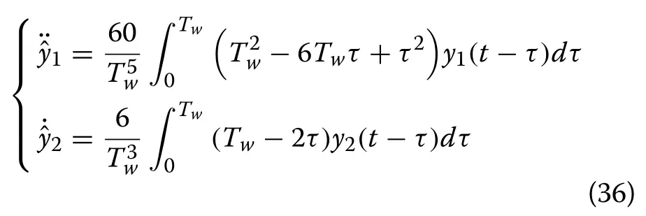
where Twdenotes the width of the sliding window containing the output measurements of the system during the period [t −Tw, t][36, 37].The value of Twcan be selected as an integral multiple of the sampling period,i.e., Tw=MTswhere M ∈N+.In practice, the appropriate selection of Twneeds to consider a trade-off between good estimation performance and noise attenuation.
Substituting (34) into (32), the dynamics of the tracking errors e1and e2are governed by:

Consequently, if the unmodeled system dynamic Fiis well estimated such that−Fi≈0 , i=1,2 , the dynamics of the tracking errors (37) can be expressed as

This implies that the errors e1and e2converge asymptotically towards the origin.The control parameters Kp1,Kd1and Kp2are selected in order to stabilize the ideal dynamics of the tracking errors (38) and to achieve satisfactory tracking performance for both errors e1and e2.
4.4 Simulation results
This subsection validates the designed model-free control scheme through an extensive simulation study using Matlab/Simulink.First, the controller performances are evaluated under normal conditions, defined by irradiation of 1 kW/m2and ambient temperature of 25 °C.To assess the robustness and disturbance rejection of the developed model-free controller, simulations are then performed under external disturbance(variable irradiance).The block diagram of the gridconnected PV system and its controller is depicted in Fig.4.It consists of a PV generator, a three-phase grid, a DC/AC three-phase converter, a MPPT tracker and the MFC controller.The DC-link voltage reference vdcris provided from the MPPT block based on the well-known Incremental Conductance (InC) MPPT method [4].The desired iqris set to 0 in order to have unity power factor.The two output control signals, u1and u2of the MFC controller, are used to provide the phase reference voltages which are used to generate the switching signals of the converter based on the conventional sinusoidal PWM.
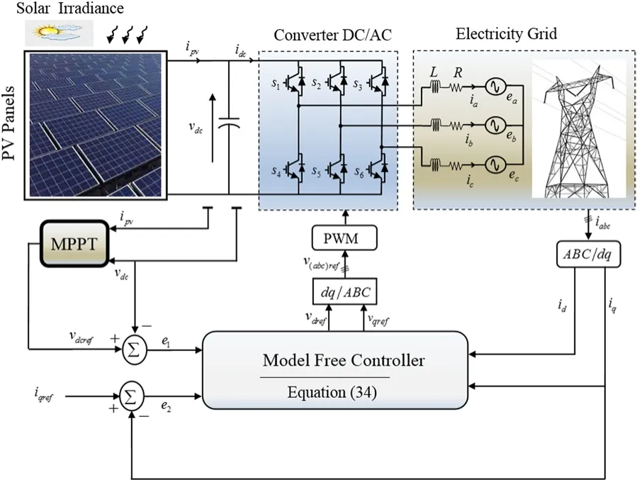
Fig.4 Proposed MFC controller applied to the grid‑connected PV system
The MFC controller (34) is implemented with a sampling time of Ts=4×10⁻⁶s, and the design parameters are selected as follows: α11=−100 ,α12=−100 , α22=1000 for the control gain matrix D ,Kp1=5×10⁶, Kd1=15×102, Kp2=4×10⁴, and the width of the sliding window of the used online numerical differentiators (36) is Tw=250Ts.The parameters of the grid-connected PV system are: grid voltage (RMS)u=220 V , resistance of output filter R=0.1 and inductance L=8 mH , DC-link capacitance C =5 mF and switching frequency Fs=10 kHz .In the design,the grid-connected PV system model is assumed to be completely unknown and the controller does not require the knowledge of the system parameters as is needed in conventional model-based controllers.In fact, only the dynamic model, the system parameters and those in Table 1 are required for simulation purposes.

Table 2 Comparisons of tracking errors performance e1 =vdcr −vdc and e2 =iqr −iq
4.4.1 Operation under normal conditions
The experimental results under normal conditions are reported in Figs.5, 6, 7, 8, 9, 10.The DC-link voltage vdcand its reference vdcrare illustrated in Fig.5 (top), and the current iqand its reference iqrare given in Fig.5 (bottom).From these results, it can be seen that the DC-link voltage tracks the reference signal generated by the MPPT algorithm, while the current iqalso converges to its reference and remains approximately zero after a short transient time (about 0.1 s).Figures 5 and 6 (top) show that the output power, voltage and current of the PV generator converge with a short response time to the maximum power point defined by P =23584 W , vdc=1066 V and I =22.13 A .The d − axis grid current tends to a constant value as illustrated in Fig.7 (top), while the grid current and voltage waveforms displayed in Fig.7 (bottom) confirm that both are sinusoidal and synchronized, which implies unity power factor.
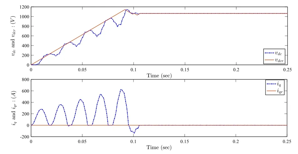
Fig.5 Operation under normal conditions: Top.DC link voltage vdc(V) (dotted line) and its reference vdcr (solid line).Bottom.Current iq(A) (dotted line) and its reference iqr (solid line)

Fig.6 Operation under normal conditions: Top.PV generator output power ppv (W).Bottom.PV generator output current ipv (A)
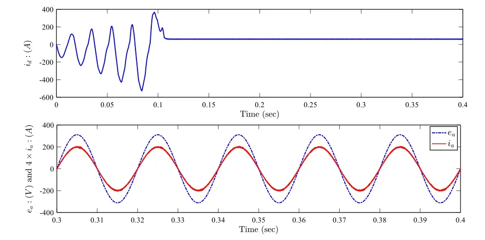
Fig.7 Operation under normal conditions: Top.Current id (A).Bottom.Grid current and voltage waveforms: Current 4×ia (A) (solid line) and voltage ea (V) (dotted line)
The time evolutions of the two estimatesandused to continuously adaptandare depicted in Fig.8.System behavior for a step change in current reference iqrapplied at 0.6 s is illustrated in Fig.9.As seen from Fig.9(top), the current iqrapidly reaches its new reference of 10 A, and consequently, the grid current and voltage become out of phase.However, when the reference iqris back to 0 at 0.7 s, the current iqfollows this new value and the grid current and voltage are again in phase as shown in Fig.9 (bottom).The harmonic spectrum of the current injected into the grid is displayed in Fig.10.As seen, the low order harmonics are attenuated, the THD is less than 5% and each individual harmonic is also very low compared to the limits in the IEEE standards [38].

Fig.8 Operation under normal conditions: Top.Estimate .Bottom.Estimate

Fig.9 Operation under normal conditions with step change in iqr :Top.Current iq (A) (dotted line) and its reference iqr (solid line).Bottom.Grid current and voltage waveforms: Current 4×ia (A) (solid line) and voltage ea (V) (dotted line)

Fig.10 Harmonic spectrum of the current injected into electrical grid
4.4.2 Operation under external disturbance (variable irradiance)
Here the performance of the MFC controller when operating under a rapid change in solar irradiance is examined.The scenario adopted in this test for solar irradiance variation is depicted in Fig.11.Simulation in the presence of radiation changes using the control law (34) without the nonlinear compensation term, in order to elucidate the important role of the real-time update of the local model.The results of the test under variable irradiance are shown in Figs.12, 13, 14, 15, 16.From these results,it can be seen that any decrease/increase in irradiance G leads to a decrease/increase of the voltage, the current and the power of the PV generator, which allows it to quickly reach the instantaneous MPP.
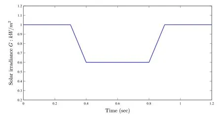
Fig.11 Solar Irradiance G versus time (s)

Fig.12 Operation under variable irradiance: Top.DC link voltage vdc(V) (dotted line) and its reference vdcr (solid line).Bottom.Current iq(A) (dotted line) and its reference iqr (solid line)

Fig.13 Operation under variable irradiance: Top.PV generator output power ppv (W).Bottom.PV generator output current ipv (A)
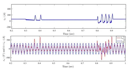
Fig.14 Operation under variable irradiance: Top.Current id (A).Bottom.Grid current and voltage waveforms: Current 4×ia (A) (solid line) and voltage ea (V) (dotted line)
The controlled system with the MFC controller exhibits a fast transient behavior under sudden change in solar irradiance as illustrated by Figs.12 and 14 (bottom).The MFC forces the DC link voltage vdcto rapidly attain its updated reference in order to reach the new MPP.Moreover, the time evolution of the q-axis grid current,illustrated in Fig.12 (bottom), reveals that iqis not influenced by solar irradiance changes.This means that the power factor is not affected and remains unity.Figure 14(bottom) shows that despite the effect of the external disturbance (change in solar irradiance) the grid current and voltage remain in phase.
In Fig.15, it is noted that the estimatesandchange according to the variation of solar irradiance G ,This allows the updating of the termsandFigure 16 describes the results achieved using the MFC controller without nonlinear compensation.As can be seen,because of the effect of variation in solar irradiance, both the DC-link voltage vdcand current iqdo not follow their reference curves from 0.9 s, which proves the important role that the nonlinear compensation term plays in control performance and in dealing with unknown uncertainties.Indeed, the real-time update ofandin the nonlinear compensation term, based on the numerical differentiator (36), significantly improves the efficiency and the robustness of the MFC controller against system parameter uncertainties and external disturbances.
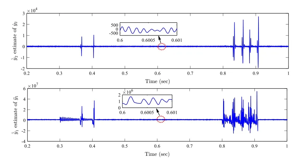
Fig.15 Operation under variable irradiance: Top.EstimateBottom.Estimate
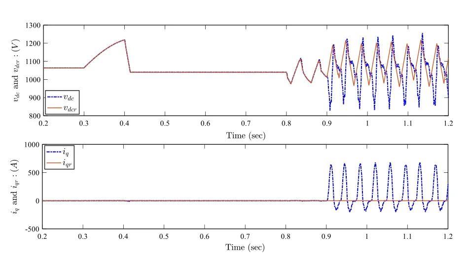
Fig.16 MFC without nonlinear compensation: Top.DC link voltage vdc (V) (dotted line) and its reference vdcr (solid line).Bottom.Current iq(A) (dotted line) and its reference iqr (solid line)
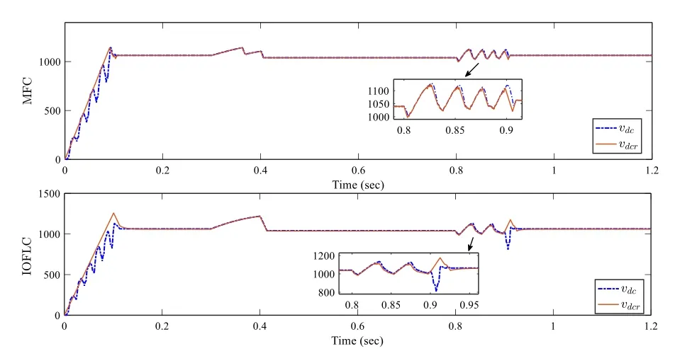
Fig.17 Comparative study: Top.DC link voltage vdc (V) (dotted line)and its reference vdcr (solid line) with MFC controller.Bottom.Dc link voltage vdc (V) (dotted line) and its reference vdcr (solid line) with IOFLC controller
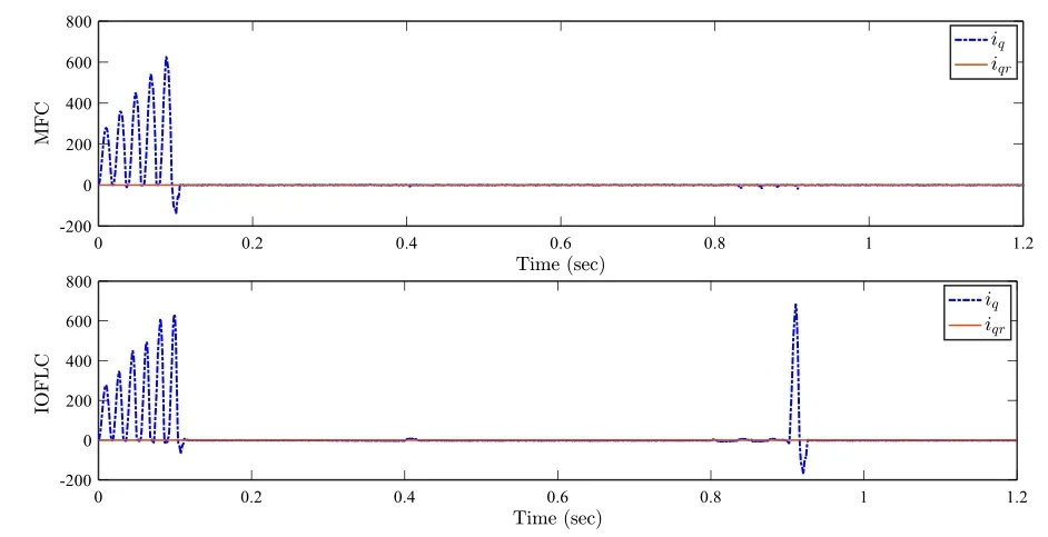
Fig.18 Comparative study: Top.Current iq (A) (dotted line) and its reference iqr (solid line) with MFC controller.Bottom.Current iq (A)(dotted line) and its reference iqr (solid line) with IOFLC controller
4.4.3 Comparison with a model‑based controller
Finally, in order to examine the performance of the proposed model-free control scheme for a grid-connected PV system, a comparative study is conducted between the proposed controller and the model-based Input Output Feedback Linearization Control (IOFLC) introduced in [4].This comparative study is performed with the same simulation parameters and under the same atmospheric conditions, at an ambient temperature of 25 °C and with a variable irradiance G as in Fig.11.As can be observed in Figs.17 and 18, the obtained curves of the DC-link voltage vdcand current iqhighlight the superiority of the tracking performance achieved with the MFC controller over the IOFLC controller [4].The transient behavior with the MFC controller is faster than the IOFLC controller.In addition, the tracking performance of the grid-connected PV system with the MFC controller is less sensitive to the effect of the irradiance variation than the IOFLC controller.
A qualitative comparison between the MFC controller and the IOFLC controller has also been performed and the results are summarized in Table 2.The main characteristics of the tracking errors e1=vdcr−vdcand e2=iqr−iqobtained by the two different implementation methods are used to examine the performance of each controller in the time interval of [0.2 s, 1.2 s].
The average absolute values of the errors ei, i=1,2 ,over the duration of the test, the range of eias well as the standard deviation of eiare used as performance indices.From the results in Table 2, it is clear that the proposed MFC control scheme achieves a better closed-loop system performance than the IOFLC controller.
5 Conclusion
In this paper, the problem of controlling grid-connected PV systems is considered using a model-free control scheme based on a numerical differentiator.A continuously updated local model is used to estimate the unknown nonlinear dynamics of the overall system.An efficient model-free control law is designed using the updated local model to achieve the control objectives.The ability and the performance of the proposed MFC controller have been examined through in-depth simulations supplemented by comparative studies.These have shown that the closed-loop system response with the MFC controller exhibits good tracking performance and robustness against external disturbances.Future work will focus on the extension of the designed model-free control scheme to a grid-connected hybrid wind/PV distributed generation system.
Abbreviations
Rs: Series resistance; Rsh: Shunt resistance; ipv: PV output current; vdc: PV output voltage; iph: Generated photocurrent; G: Solar irradiance; T: Cell’s working temperature; iD: Current through the diode; ish: Current flowing through the resistor Rsh; I0: Cell’s reverse saturation current; q: Electron charge; n: Duality factor of the diode; K: Boltzmans constant; Ns: Series cells; Np: Parallel cells; isc: Short circuit current at reference temperature and radiation; I0R: Cell reverse saturation current at the reference temperature Tref; ki: Short circuit current temperature coefficient; Eg: Band‑gap of the semiconductor used in the cell;va,b,c: Three‑phase voltage of the converter; ia,b,c: Three‑phase current injected into the grid; ea,b,c: Three‑phase line voltage of the grid; R: Total resistance of the filter; L: Total inductance of the filter; C: DC‑link capacitance; id,q: D‑q components of the grid current; vd,q: D‑q components of the output voltage of the converter; ed,q: D‑q components of the grid voltage; f: Grid frequency;ϕd,q: Disturbance terms in phase currents; α: Non‑physical constant parameter;υ: Order of derivative; u: Control input vector; F: Unmodeled system dynamics;D: Control gain matrix.
Acknowledgements
The authors acknowledge the support for this work provided by the general directorate of scientific research and technological development of the Minis‑try of Higher Education and Scientific Research of Algeria.
Authors’ contributions
AB: Conceptualization, data curation, formal analysis, investigation, methodol‑ogy, project administration, resources, software, validation, visualization, writ‑ing—original draft.S‑AT supervision, validation, visualization, writing—review& editing.SL: conceptualization, formal analysis, investigation, methodology,supervision, validation, visualization, writing—review & editing.NB: Supervi‑sion, visualization, writing—review & editing.All authors read and approved the final manuscript.
Authors’ Information
Ahsene Boubakir (1981‑) male, Ph.D.and associate professor, the main research direction isrenewable energy, adaptive control, model‑free control and sliding mode control.
Sid‐Ahmed Touil (1991‑) male, Ph.D.and assistant professor, the main research direction is electromagnetic compatibility in power electronics, control of power converters and renewable energy.
Salim Labiod (1972‑) male, Ph.D.and professor, the main research direction is fuzzy/neural control, nonlinear control, adaptive control and fault tolerant control systems.
Nasserdine Boudjerda (1964‑) male, Ph.D.and professor, the main research direction is electromagnetic compatibility in power electronics, control of power converters and renewable energy.
Funding
The general directorate of scientific research and technological development of the Ministry of Higher Education and Scientific Research of Algeria.
Availability of data and materials
Not applicable.
Declarations
Competing interests
The authors declare that they have no known competing financial interests or personal relationships that could have appeared to influence the work reported in this paper.
 Protection and Control of Modern Power Systems2021年0期
- Protection and Control of Modern Power Systems的其它文章
- Maximum production point tracking method for a solar-boosted biogas energy generation system
- Effective damping of local low frequency oscillations in power systems integrated with bulk PV generation
- A novel out of step relaying algorithm based on wavelet transform and a deep learning machine model
- Design of protection and control scheme for hybrid nanogrid
- A weighted voltage model predictive control method for a virtual synchronous generator with enhanced parameter robustness
- System bias correction of short-term hub-height wind forecasts using the Kalman filter
