Effective damping of local low frequency oscillations in power systems integrated with bulk PV generation
Ahmed Hesham Abd El‑Kareem, Mohamed Abd Elhameed and Mahmoud M.Elkholy
Abstract High penetration of renewable sources into conventional power systems results in reduction of system inertia and noticeable low‑frequency oscillations (LFOs) in the rotor speed of synchronous generators.In this paper, we propose effective damping of LFOs by incorporating a supplementary damping controller with a photovoltaic (PV) generat‑ing station, where the parameters of this controller are coordinated optimally with those of a power system stabilizer(PSS).The proposed method is applied to damp local electromechanical modes by studying a system comprising a synchronous generator and a PV station connected to an infinite bus.The PV station is modeled following the instruc‑tions of the Western Electricity Coordinating Council.The problem is modeled as an optimization problem, where the damping ratio of the electromechanical modes is designed as the objective function.Constraints including upper and lower limits of decision parameters and damping ratio of other modes are considered by imposing penalties on the objective function.Different optimization algorithms are used to pursue the optimal design, such as political,improved gray wolves and equilibrium optimizers.The results validate the effectiveness of the proposed controller with PSS in damping local modes of oscillations.
Keywords: Low frequency oscillations, Damping controller, PV, WECC
1 Introduction
In recent years, worldwide, large scale renewable generation, such as photovoltaics (PVs) and wind plants,have been installed and connected to electricity grids by inverters [1, 2].The expansion of renewable energy impacts power system stability and control.One of the main effects is the reduction in system inertia, and hence,power systems are more vulnerable to instability when subjected to disturbances [3].Moreover, low frequency oscillations (LFOs) in the rotor speed of conventional synchronous generators (SGs) may be prolonged because of the lack of damping torque, especially when generators are equipped with static exciters and automatic voltage regulators (AVRs) [4].An AVR changes the current in the field winding.This counteracts the induced current of the damper winding, and consequently, it deteriorates the damping process [5, 6].
LFOs are excited by system disturbances such as sudden load changes, switching events and malfunction of system controllers.Power system stabilizers (PSS) [7]are the practical controllers to dampen these LFOs [8,9].PSS generates a stabilizing signal to produce a damping torque on a generator rotor while the created torque component must be in phase with the speed deviation[10, 11].However, other controllers such as those added to flexible AC transmission systems (FACTs) devices have also been investigated to assist the action of PSS [12, 13].
Renewable energy resources (RESs) are usually connected to grids via inverters, and usually operate at the maximum power point [14–16].Up to now, grid codes do not contain regulations for adding damping controllers to these sources.However, increase in the penetration level of RESs makes it urgent to investigate the effectiveness of adding supplementary damping control via RESs’ control circuits.
Most inverters are dependent on a phase locked loop(PLL) to be synchronized with the grid [1].However, a PLL is not sufficient to overcome these power system disturbances because it depends on the frequency produced by the synchronous generators.This leads to a loss of synchronism with the grid and results in system instability [1].Therefore, research has established the concept of the virtual synchronous generator (VSG) [3, 17] as a solution for the stability problem while supporting the inertia of the power system.A VSG emulates the dynamic performance of a real synchronous generator (SG) [14].In [18], the frequency and voltage of the infinite bus are used as input signals to control the output inverter with pulse width modulation to enhance system stability.
The Conventional PSS (CPSS) system for SG has been examined and found to be inefficient during turbulence and large-scale operation, as it cannot effectively damp LFOs [19, 20].Several methods have been used to optimize CPSS to improve its performance [7], while other types of optimization methods and intelligent controllers[21, 22] have also been investigated to tune and improve control action.Those methods are categorized by [20]into linear and non-linear design methods.
Linear design methods include: (1) pole placement[23, 24], where special root locus and participation factor techniques are used to adjust and select the gains while using dominant modes in the controller design for a multi-machine system[25]; (2) pole-shifting [26], where a minimum variance algorithm is used to tune the PID parameters of PSS by continuous imposition for the system input–output relationship from the measured inputs and outputs and the gain settings of the self-tuning PID stabilizer are adjusted in real-time; (3) linear quadratic regulator formulation [27], where a differential geometric linearization approach is used and an appropriate signal from the secondary bus of the step-up transformer is considered as input to the internal generator bus; and(4) other linear design methods, such as linear matrix inequalities [28], linear optimal control [29], quantitative feedback theory [30], eigenvalue sensitivity analysis[31, 32], sliding mode control [33] and conventional P-Vr Method [34].
Non-linear design methods [35] depend on either heuristic optimization or nonlinear control theory.Based on heuristic optimizers, particle swarm optimization (PSO)is applied in [36–38] to design LFOs damping controllers.In [39], Tabu search is used to avoid computation of eigenvalues and sensitivity factors, whereas in [40, 41], a genetic algorithm is used to specify the objective function and place finite bounds on the optimized parameters to enhance power system stability.Other non-linear design methods are adaptive automatic [42, 43], self-tuning and self-scaling [44], heuristic dynamic programming[45], and the Lyapunov method [46].
To support the operation of PSS, other damping controllers are designed via FACTs devices [47–49].These use power electronics to enhance LFO damping.Heuristic optimization methods are investigated to optimize the parameters of the FACTs controllers [50] to maintain power system stability, such as the bee algorithm [51],evolutionary fuzzy lead-lag controller [52] with advanced continuous ant colony optimization [53], artificial neural networks [54], the hybrid harmony search algorithm and ant system [55], and many biogeographical-based optimizations [56].
In this paper, SG is represented by the third order model using Park’s transformation [6, 57].The generator is equipped with a static exciter, AVR and PSS.Western Electricity Coordinating Council (WECC) instructions[58] are followed for PV modeling, and a damping controller is added via the active power control loop of the PV-WECC model.Since no heuristic method fits all engineering optimization problems, new methods are still being developed, including political (PO) [59, 60],equilibrium (EO) [61] and improved-gray wolf optimizers (IGWO) [62].Those algorithms are used for optimal coordination between the proposed controller and PSS.The parameters of the proposed controller along with those of PSS in the studied system are found in the MATLAB environment, which is also used to examine the quality of the results.Various scenarios are studied in order to evaluate the performance and the optimal design of damping controllers.The first scenario discusses the effect of field voltage and AVR on system damping.In scenario 2, the proposed damping controller is designed and applied to the studied system, while in scenario 3, a coordinated design between the proposed controller and PSS is introduced.
The main contributions of this paper are: (1) suggesting a supplementary damping controller to energy storge devices equipped with bulk PV stations for LFO damping, (2) novel application of PO to design the proposed damping controller (PDC) (3) justifying the effectiveness of the PDC by comparisons with other challenging algorithms, (4) verifying the performance of the PDC against system disturbances and comparing its performance with that of PSS.
The rest of this paper is organized as follows.Section 2 presents the mathematical model of SG connected to an infinite bus and a bulk PV station.In Sect.3, the applied optimization algorithms are briefly introduced, and the problem definition along with the imposed constraints are found in Sect.4.In Sect.5, various scenarios are studied after many independent runs of the optimization methods, and the summarized results are analyzed and discussed.Finally, conclusions are drawn in Sect.6.
2 Overall system modelling
This section introduces the mathematical model of the system under study.This is described by the single line diagram in Fig.1a.The proposed controller is suggested for utility scale PV [63, 64].There are many examples of bulk PV stations worldwide such as [65]: Bhadla solar park with a capacity of 2.245 GW, Pavagada solar park in Karnataka, India, with a capacity of 2.05 GW, and Al Dhafra solar project, Abu Dhabi with a capacity of 2GW and Benban station in Aswan-Egypt with a capacity of 2 GW (1.4 GW is already installed) [2].
Some utility size PV stations such as that in Benban are connected via step up transformers to the transmission network, and this one is very close to the high dam hydro power station.For simplicity, electrically close plants can be modeled as being on the same bus.However, the short transmission line has been placed in series with the PV station [66] as shown in Fig.1a.Detailed configuration of the PV station is shown in Fig.1b.The PDC output signal is added to the charging controller of battery storage.

Fig.1 Bulk PV station with SG connected to infinite bus
2.1 Modelling of SG connected to an infinite bus
SG is usually modeled using the Park equations [6, 57]to express and simulate its physical description [67].Analyzing SG in (the d–q) axis rotor reference frame by transformation from (a–b–c) stator reference frame, the d–q stator voltages are given by:

The voltage in the field winding is:

The electromagnetic torque and rotor equation of motion are [68]:

Connection with an infinite bus is represented by:

To determine the steady state quantities, the derivative operatoris set to zero and ωris equal to the synchronous speed.LFOs are studied through small-signal stability analysis [4, 6], where system equations are linearized around the steady state initial operating conditions[69].The SG is equipped with the IEEE ST1A excitation system and PSS [7] shown in Fig.2a, b [10, 11],respectively.

Fig.2 Block diagram of excitation system with PSS
The generated voltage of the synchronous generator Vtis given by:

2.2 Modelling of PV bulk stations
Bulk PV stations have two main control loops as modeled by the Western Electricity Coordinating Council(WECC) [58] as shown in Fig.3.
These loops are the active and reactive power control paths, while the reactive power control loop may also be used for voltage control.As shown in Fig.3, the proposed damping controller (PDC) is similar to a PSS, and is attached to the active power control loop while the deviation in rotor speed is the input to PDC.
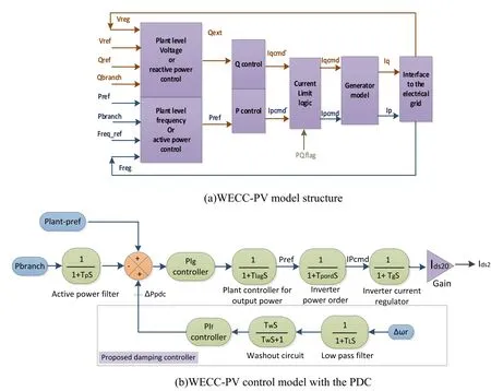
Fig.3 Overall Model WECC Structur
The proposed controller is simpler in construction than a virtual synchronous generator.However, its performance is similar to PSS.Therefore, this additional controller reinforces the operation of PSS in damping electromechanical oscillations.One advantage of the proposed damping controller over PSS is that it is independent of the excitation level of the generator.For example,in lag power factor operation, the PSS action sometimes is limited because of a saturation effect.
The output of the active power control loop is the injected direct (active) current into the point of common connection.Electrical power output from the PV station is calculated by:

The transmission line current in the d–q frame is the sum of the SG current and the output current of the PV station, i.e.:

Power systems are multi-input multi-output systems,and it is common to describe their differential equations in the state space form:

The electromechanical modes are determined using participation factors [4], and the damping ratios of these modes are calculated and considered as the objective function here.
3 Algorithms of optimization
No single optimization method can be perfect for all optimization problems, as optimization methods are random in nature and differ in their exploration and exploitation search methods.Considering the issues of LFOs, PO is applied in this paper and its performance is compared with EO and IGWO.PO is a recently developed optimization technique, one which has a formidable execution ability in solving engineering optimization problems additional to complex multimodal functions[59, 60].It has an excellent exploration capability and convergence speed in early iterations [59].The method was inspired by the response of human reaction during political processes, and follows a novel position updating strategy, called recent past-based position updating strategy, which is the mathematical modelling of the learning behaviours of the politicians from the previous election.PO has proven its superiority when compared with competing algorithms such as whale optimizer [70], ant lion,grey wolf, moth flame and many others [60].The procedure of PO is encapsulated in Fig.4, while more details of PO can be found in [59].

Fig.4 Flow chart of PO
The authors in [59, 60] measured and calibrated the PO with 50 unimodal, multimodal, and fixed dimensional functions against 15 state-of-the-art algorithms and compare the performance of PO with these algorithms.The algorithms vary from well-matured algorithms like the particle swarm optimizer to recently developed algorithms such as sea lion and spider monkey optimizers and many others.Statistical measures and empirical investigation proved that PO either outperforms the others or performs equivalently.This motivated the authors to apply this algorithm in PDC design.
The I-GWO algorithm follows a strategy of learningbased hunting inherited from the individual hunting behavior of wolves in nature.This depends on sharing information between wolves to improve diversity and enhance local and global searches.This leads to a balance in exploitation and early convergence of the algorithm.EO was inspired by estimation of the equilibrium and dynamic states that control mass balance models.The EO algorithm follows a strategy of search agent by guessing that the mass is a group of particles (solutions) having a certain concentration (positions).The search agents randomly update their concentrations to estimate the state of equilibrium(optimal value) while maintaining the allowable limits.
4 Problem definition
The proposal is to design the PSS and additional damping controllers optimally using the PO heuristic method.The objective function (OF) is to maximize the electromechanical modedamping ratio and obey certain constraints on decision parameters and other modes’ damping ratio.Since the optimizers are designed for a minimization process, the OF is the inverse of the damping ratio:

The constraints on PIf, PIgand PIPSSparameters, and the accepted minimum damping ratio of any mode (0.2)are described by:

Constraints in (17) are implemented naturally by the optimizers, while those in (18) are handled by penalties imposed on the OF.
5 Results and discussions
The system under study consists of a 555 MVA SG equipped with a static exciter and an AVR, a PV bulk station of 50 MW, and is connected to an infinite bus through a transmission line.The overall system data is given in “Appendix” [4, 58].It is worth mentioning that the modelling of the system components along with optimization methods are conducted in the MATLAB environment.The system is disturbed by a sudden deviation in Pmof 100 MW to excite the electromechanical modes,and eigenvalues and system responses are calculated to evaluate the OF.Different scenarios are studied to evaluate the system performance under different conditions,including: (1) constant field voltage (CFV) and with AVR;(3) high PV penetration with PDC; and (3) optimal coordination between PDC and PSS.
5.1 Scenario 1: effect of filed controllers on LFOs
In this scenario, it is assumed that SG is operated at constant field voltage (CFV).This case study represents the situation where the AC voltage regulator malfunctions and the control is transferred to the DC regulator.Moreover, the effect of AVR action is encountered by incorporating the static excitation system with the deactivation of PSS.In both cases, eigenvalues corresponding to (are concluded to assess the dynamic performance ( ζ and ωd) of SG.The electromechanical modes are listed in Table 1.

Table 1 Electromechanical modes
Entries of Table 1 indicate ζ of SG is 3.4706×10⁻⁵with CFV, and −0.0219 with AVR.The results coincide with those found in literature describing the effect of static exciters and AVR on electromechanical modes [4, 32].Figures 5 and 6 confirm the entries in Table 1 where the responses of rotor speed and electromechanical torque are stable in the case of CFV but with a very long settling time of 2×10⁴s due to the weak damping, whereas the corresponding responses are unstable in the case of AVR with deactivated PSS.
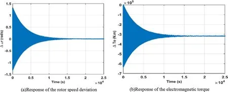
Fig.5 Responses in CFV case

Fig.6 Response with AVR and deactivated PSS
5.2 Scenario 2: LFO damping with the PDC
In this case study, it is assumed that the system is penetrated with a bulk PV station, while the proposed PDC is designed as described in Fig.3b.The three optimizers,namely PO, EO, and I-GWO, are applied to determine the optimal values of PIfof PDC and PIgcontroller of the main active power loop of the WECC model.The defined upper and lower constraints are listed in Table 2.These are decided after many trials to operate the system within the stable region.
Statistical analysis is performed after 20 independent runs of the three algorithms.Table 3 compares the performance of the three optimizers in searching for the desired decision parameters inside the allowable constraints.As seen, PO has the minimum OF(corresponding to maximum damping ratio) and lowest standard deviation of the three methods.
The signatures of the convergence of the three methods are shown in Fig.7.As seen, although EO reaches a final solution before PO, the quality of the solution obtained by PO is the best.

Fig.7 Convergence curves
The electromechanical modes in this case are listed in Table 4.The damping ratios of the electromechanical modes ζ are 0.2424, 0.2337 and 0.2192 with PO, I-GWO and EO, respectively.Therefore, PO is better than EO and I-GWO in designing the PDC because it parses the optimal PI parameters at the lowest standard deviation with maximum damping ratio for the electromechanical modes.
Figure 8 confirms the entries in Table 4 where the effect of inferred PI parameters from the optimization methods are noticeable on the system response.The responses of the rotor speed and electromechanical torque basedon PO parameters are better than those of EO, I-GWO,where a settling time of 2.4 s is observed.

Table 2 Constraints on optimization process

Table 3 OF statistical measures

Table 4 Optimal values for PI parameters

Fig.8 Response with PDC
5.3 Scenario 3: coordination between the PDC and PSS
In this case study, it is proposed to coordinate the actions of PDC and PSS in the design stage.The three optimizers are applied to obtain the optimal values of the PIPSScontroller of PSS and PIfof PDC, in addition to the main PIgcontroller of the main active power loop of the WECC model.The upper and lower constraints are defined in the same ranges as given in Table 2.Convergence curves are plotted in Fig.9 for comparison among the three optimizers.As seen, PO again proves its good performance compared to EO and I-GWO due to its exploration capability for OF in early iterations.Although the design is an offline problem and time is not a critical factor, convergence traits are introduced in this paper to give a bigger picture on the three algorithm behaviors.This can help others if one of the algorithms is used for online problems.

Fig.9 Convergence curves
The electromechanical modes along with the summarized controller parameters are listed in Table 5.Again,PO results in a better damping ratio of the electromechanical modes, where ζ is 0.376, 0.3550 and 0.3184 with PO, IGWO and EO, respectively.
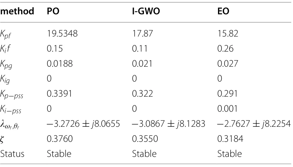
Table 5 The optimal values of PI controllers

Table 6 The comparison of previous scenarios
System responses with the designed controllers and with the step input in mechanical torque are illustrated in Fig.10.As seen, the settling time with PO-based parameters is 2.5 s.When the two controllers of PDC and PSS work together, better damping of LFO is achieved.
The temporary sharing of a PV system is illustrated in Fig.10c, where the maximum current deviation is about 0.5 p.u for 2.5 s.

Fig.10 Response with PDC and PSS
Table 6 summarizes the performance of the studied system scenarios regarding settling time, damping ratio,and overshoot of electrical torque.
To demonstrate the effectiveness of the PDC under different operating conditions, system response with a disturbance at different loading levels is shown in Fig.11.Although the controller is designed at base load level, it shows a satisfactory response with other load levels.Figure 12 shows the system response with different power factors.As expected, the system is less stable with a leading power factor, however it is still stable.

Fig.11 Step response of speed and electromagnetic torque at different loading levels
6 Conclusions
The PO method has been applied effectively here to design a supplementary damping controller via the active power control loop of a bulk PV station.A system consisting of an SG equipped with AVR and PSS, and a bulk PV station connected to an infinite bus is proposed to study the local modes of oscillations.The PV station is modelled using WECC control loops.Three scenarios are considered in order to highlight the importance of PDC.Statistical measures are applied among PO, IGWO and EO to evaluate their performance in deciding the controller parameters.These statistical measures along with the convergence traits validate the good performance of PO and thus its use is recommended in designing damping controllers.In addition, coordination between PDC and PSS results in a better damping ratio of the electromechanical modes where it is improved from 24.2%with PDC alone to 37.6% with both controllers.Furthermore, deviations in speed and electromagnetic torque responses to a step change in input mechanical torque illustrate the good damping of the electromechanical modes using PDC.

Fig.12 Step response of speed and electromagnetic torque at different PF
Appendix
System parameters.

Parameter Value Unit rs 0.0031 Ωrfr 0.0715 Ωlls 0.4129 × 10⁻³ H lmd 4.5696 × 10⁻³ H lmq 4.432 × 10⁻³ H pb 499.5 × 10⁶ W P 2 Pole J 27,547.8 N.m2 vll 24,000 V F 50 Hz Hz Tr 0.02 s KA 196 p.u TA 0.001 s KF 0.001 p.u TF 0.62 s TL 0.01 s TW 30 s Ppv 50 × 106 W vll 24,000 V Tlag 0.09 s Tpord 0.01 s Tg 0.01 s Tp 0.02 s
Abbreviations
Acknowledgements
Authors would like to thank Zagazig university for providing necessary research facilities.
Authors’ contributions
Ahmed Hesham as the corresponding author, contributed significantly to the research, writing, and submission of the paper.Mohamed Abd Elhameed and Mahmoud M.Elkholy provided decisive comments and technical supervision for the paper.All the authors read and approved the submitted manuscript.
Funding
No funding was received.
Availability of data and materials
All data generated or analyzed during this study are included in the published article.
Declarations
Competing interests
The authors declare that they have no known competing financial interests or personal relationships that could have appeared to influence the work reported in this paper.
 Protection and Control of Modern Power Systems2021年0期
- Protection and Control of Modern Power Systems的其它文章
- A comprehensive review of DC fault protection methods in HVDC transmission systems
- Application of a simplified Grey Wolf optimization technique for adaptive fuzzy PID controller design for frequency regulation of a distributed power generation system
- A critical review of the integration of renewable energy sources with various technologies
- Operational optimization of a building-level integrated energy system considering additional potential benefits of energy storage
- An integrated multi-energy flow calculation method for electricity-gas-thermal integrated energy systems
- Sliding mode controller design for frequency regulation in an interconnected power system
