A comprehensive review of DC fault protection methods in HVDC transmission systems
Mohan Muniappan
Abstract High voltage direct current(HVDC) transmission is an economical option for transmitting a large amount of power over long distances.Initially, HVDC was developed using thyristor-based current source converters (CSC).With the development of semiconductor devices, a voltage source converter (VSC)-based HVDC system was introduced, and has been widely applied to integrate large-scale renewables and network interconnection.However, the VSC-based HVDC system is vulnerable to DC faults and its protection becomes ever more important with the fast growth in number of installations.In this paper, detailed characteristics of DC faults in the VSC-HVDC system are presented.The DC fault current has a large peak and steady values within a few milliseconds and thus high-speed fault detection and isolation methods are required in an HVDC grid.Therefore, development of the protection scheme for a multi-terminal VSC-based HVDC system is challenging.Various methods have been developed and this paper presents a comprehensive review of the different techniques for DC fault detection, location and isolation in both CSC and VSC-based HVDC transmission systems in two-terminal and multi-terminal network configurations.
Keywords: HVDC, VSC, Multi-terminal DC grid, DC fault, Fault detection and location, Fault isolation
1 Introduction
High voltage alternating current (HVAC) is widely used for short to medium distance power transmission but may not be applicable for long distance power transmission because of the high charging current of cable capacitance, high losses, absence of asynchronous operation, difficulty in control of power flow, the need for reactive power compensation and having issues of skin and Ferranti effects.Because of these drawbacks in HVAC transmission, application of high voltage direct current (HVDC) has increased significantly [1–3] and HVDC transmission has become an economical choice for the transfer of high power over longer distances.
In the early stage, the current source converter (CSC)based HVDC system was used for the transmission of power.CSC-based HVDC systems use thyristors, and can apply to very high power rating with low losses (typically around 0.7%).However, thyristors can only be turned-on with no turn-off capability which means they cannot be controlled to interrupt a fault current.In addition, a CSC-based HVDC system requires large filters which increase the capital cost and is vulnerable to AC side faults which can lead to commutation failure[4–6].Given these issues, HVDC systems using voltage source converters (VSC) have been developed.
A VSC uses an insulated gate bipolar transistor(IGBT)and can operate with weak AC networks such as offshore wind farms because of its fast and robust control,and ability to maintain a constant DC voltage even when the power direction reverses.Therefore, VSC HVDC systems have seen rapid development in the past few years.However, VSC has some drawbacks such as sensitivity to DC faults, high losses (typically around 1.6%)and lower power ratings [7–9].
Early HVDC systems were largely two-terminal pointto-point connections.In such two-terminal configurations,power flow is interrupted if any fault occurs in a DC line.Therefore, multi-terminal (MT) DC networks are developed which are fairly straightforward since VSC can maintain a constant DC voltage when the power direction changes.MT configurations provide better reliability and lower costs and losses because of the reduced number of terminals required compared to equivalent multiple two-terminal configurations.They can use different network topologies such as radial and mesh connections.Mesh connection of the MT network provide higher reliability and flexibility than the radial network[10–12].
Protection of an HVDC transmission line is difficult when compared to that for an AC transmission line protection because of its low impedance and no zero crossing of DC current.Power electronic devices have limited overload capability, and conventional relay is not suitable for HVDC line protection.The protection of a CSC-based HVDC transmission line is less severe than a VSC-based HVDC transmission line.In the case of a VSC-based HVDC line, high-speed protection is essential because of its fast rise time and high steady state fault current.In addition, identifying the faulted line is very difficult in the case of multiterminal networks [13–15].
Detailed studies of the characteristics of DC faults in HVDC systems are presented in this paper.It provides a comprehensive review of the different techniques which can detect, locate and isolate DC faults in CSC and VSC-based HVDC transmission lines in two-terminal and multi-terminal networks.In addition, it provides recommendations for future research on protection methods for DC faults in HVDC grids.The rest of the paper is constructed as follows.Section 2 discusses the various fault studies in HVDC systems while Section 3 presents the review of the different protection schemes for DC line faults.Finally, Section 4 concludes and summarises the important observations.
2 HVDC fault studies
Various faults can exist in an HVDC system such as AC faults, internal converter faults and DC faults.Usually,faults can occur because of insulation failure caused by short circuits, switching and lightning events.The AC side faults can be divided into symmetric and asymmetric faults.When faults occur in an AC transmission line connected with CSC-based HVDC station, commutation failure can happen leading to DC voltage collapse [16].Distance relays are used to protect the AC transmission lines from such disturbances.Internal converter faults are related to device misfire / fire-through, DC link capacitor failure and flashover etc.[17]
Various faults can occur on the DC side including the line-to-line (L-L) fault, positive / negative line-to-ground(L-G) fault, and double line-to-ground (2-L-G) fault.The analysis of DC faults based on symmetric components is presented in [18].A DC fault is not very severe in CSC-based HVDC line since the fault current is limited by the large DC reactors at the DC terminals.However, a VSC-based HVDC system is vulnerable to DC faults because of the fast rise time and high peak and steady fault current [19].Therefore, DC fault protection has received considerable attention as an increased number of MT VSC-based HVDC systems are being built.The analytical and simulation studies on DC faults in HVDC systems are presented in[20–28].
2.1 DC line-to-line fault
A line-to-line fault is the worst case of DC faults in the operation of a VSC-HVDC system.The line-to-line fault has three stages including capacitor discharging, diode freewheeling and grid current feeding phases as shown in Fig.1.A VSC-based HVDC system (±150 kV test system)with current limiting reactors (CLR) is considered for the DC fault studies,and its detailed modeling is given in[29].The response of the test HVDC system under a DC lineto-line fault condition is shown in Fig.2.After the fault occurrence, the IGBTs in the VSC are blocked and the fault current flows through the antiparallel diodes.As seen in Figs.1 and 2, DC capacitor discharging action takes place first which causes the DC voltage to decrease to zero.In the second stage, the line inductor drives the current through the antiparallel diode path, while in the third stage, the converter behaves like an uncontrolled rectifier through which the grid current will flow to the fault point.
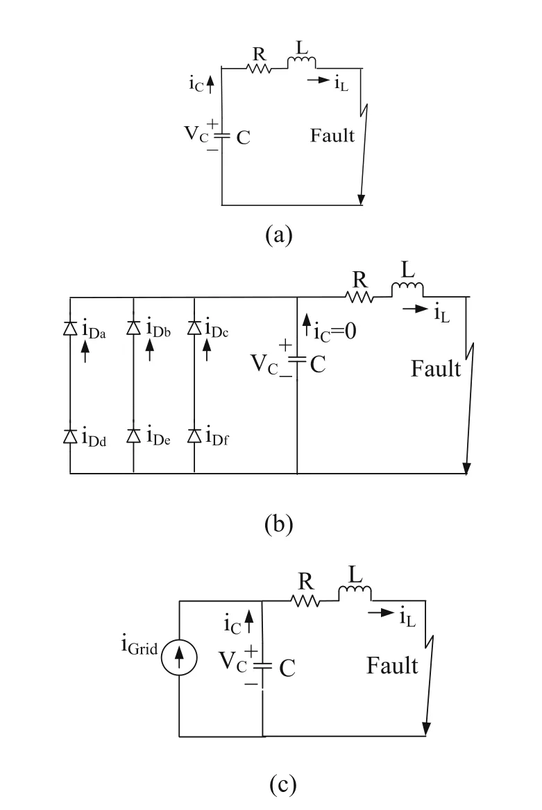
Fig.1 DC line-to-line fault.a Stage 1- Capacitor discharging phase, b Stage 2 - Diode freewheeling phase, c Stage 3-Grid current feeding phase
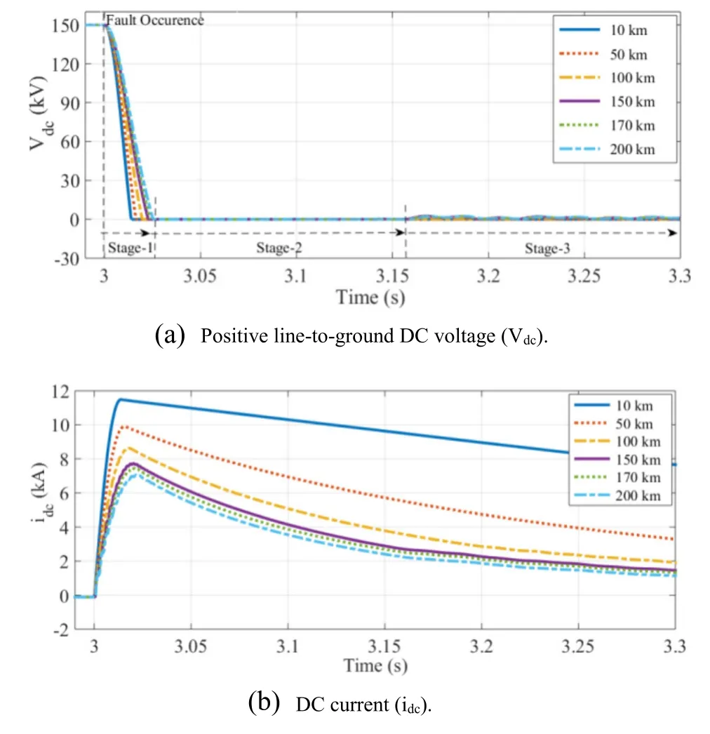
Fig.2 The response of VSC-HVDC system under DC line-to-line fault
2.2 DC line-to-ground fault
Line-to-ground faults frequently occur and are mainly dependent on the grounding of the HVDC system.In this case, the fault resistance should not be neglected since it plays a significant role in the system response.Analytical and simulation studies of the fault current contribution under line-to-ground faults from various sources such as the DC capacitor and reactor, and AC network are presented in [30–33].The pole-to-ground faults can be analyzed using two stages such as capacitor discharging and grid current feeding phases as shown in Fig.3.The response of the proposed HVDC system under a positive line-to-ground fault is shown in Fig.4.

Fig.3 DC line-to-ground fault.a Capacitor discharging phase, b Grid current feeding phase
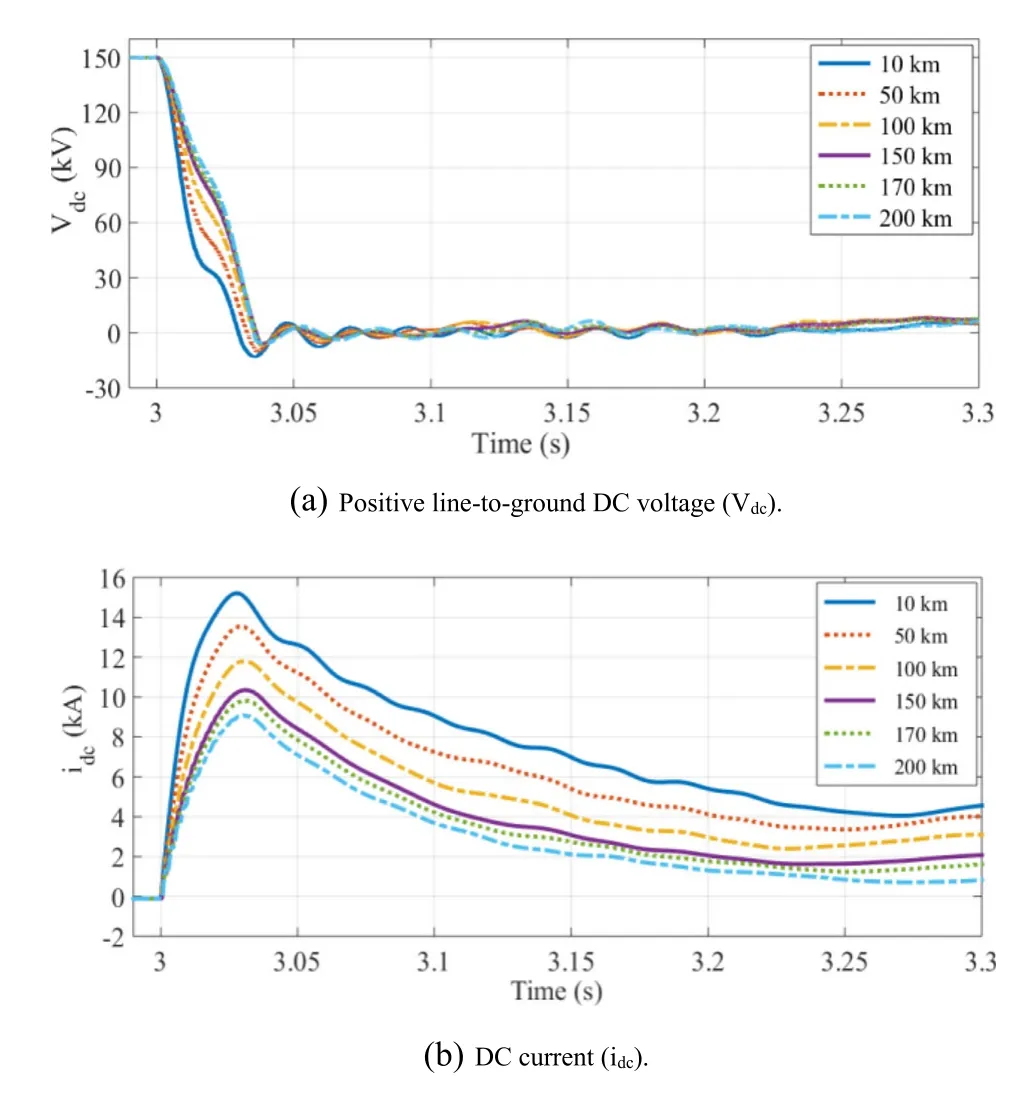
Fig.4 The response of VSC-HVDC system under positive line-to-ground fault
In the first stage,DC capacitor discharging occurs but the DC voltage will not go to zero, i.e., the faulty line voltage collapses to zero,while the non-faulted line voltage increases when the symmetric monopole configuration is used in the HVDC system.Therefore,no freewheeling diode conduction occurs in this case.In the second stage,the grid current feeding phase occurs via the antiparallel diode path in the VSC.
2.3 DC double line-to-ground fault
The responses of the DC voltage and current under double line-to-ground faults are shown in Fig.5.The faults are simulated for different distances, i.e., 10 km,50 km, 100 km, 150 km, 170 km and 200 km from the relay locations.The fault resistance is 0.2 Ω for the simulation.

Fig.5 The response of VSC-HVDC system under double line-to-ground fault
After the fault event, there are also 3 stages, i.e.,capacitor discharging phase (Stage-1), diode freewheeling phase (Stage-2) and grid current feeding phase (Stage-3).In the capacitor discharging phase,the DC voltage is discharged to zero while its decrement rate is reduced when the fault distance increases from the measurement or relay location.In Stage-2, diode freewheeling action takes place, during which the DC fault current is increased to the abnormal peak and then to the steady value.In the worst case, the peak of DC fault current goes up to 11.5 kA for the fault at 10 km distance from the relay location, while the peak DC fault current decreases when the fault distance increases.In Stage-3,the grid current feeding phase takes place, and the DC fault current reaches the steady peak value.From the simulation results it is observed that the DC voltage and current change rates decrease when the fault distance increases from the measurement or relay location.
3 DC fault protection methods in HVDC systems
3.1 Conventional protection methods
Reference [34] describes the difficulties of the conventional protection schemes such as distance, overcurrent and differential protection when applied to an HVDC grid.In overcurrent protection, the tripping action happens when the current exceeds the preset threshold value.However, the relay may trip the adjacent line, and the overcurrent protection is very often used as secondary protection for the transmission line.Differential relays operate if the difference between the sending and receiving end current exceeds the preset threshold.It is more suitable for a short distance transmission line and bus bar protection, as it takes a long time for long transmission lines.Distance relays calculate the apparent impedance by measuring the voltage and current at the relay point.This can be used to detect the fault and is used as the primary protection for AC transmission lines.However, in the case of HVDC grid protection, unlike in the AC system, the complex impedance at the fundamental frequency is different,while the accuracy of distance relays is affected by the fault resistance.Therefore, conventional relays are not suitable for HVDC grid protection and developing a suitable protection scheme for a HVDC grid is still a challenge.The derivative, second derivative, and wavelet transform (WT) based protection schemes are suggested in the paper (Reference [34]) because of the short time response.
The protection units installed in an AC grid can address only steady-state based protection [35].Here,the Fourier transform (FT) is applied to extract the magnitude and frequency information from the steady-state signals for the relay calculation.The high-frequency transient period is no longer than 10 ms and therefore, the operating time of AC grid protection is generally more than 20 ms.However, in the case of an HVDC line, the transient period is more extended than in the AC system, while the peak fault current reaches an abnormal value that cannot be tolerated by the converters.Therefore, the protection algorithm needs to be developed based on transient components instead of the fundamental frequency component.
Reference [36] discusses voltage derivative, traveling wave, current differential, and DC voltage level protection schemes.In [37], a method is presented to detect the fault based on the time difference between the two reflected waves using a correlation method.In the voltage derivative method, the derivatives of DC voltages are calculated and compared with the threshold setting for high-speed protection of the HVDC line.However, the voltage derivative method is vulnerable to fault loop impedance and long-distance faults.In the traveling wave based method, the difference between the DC voltage and current samples is used to detect the fault.The current differential protection scheme is affected by communication error and time delay, while the DC voltage level protection can be used as backup protection.It is suggested that local fault detection schemes such as wavelets and transient based protection schemes may work well for HVDC lines.
3.2 Handshaking method
In [38] and [39], a handshaking method is proposed to identify the DC fault in MT VSC-HVDC systems.AC circuit breakers (CB) with DC switches are used.These are cheaper than DC circuit breakers.If the fault occurs in a DC line, the AC circuit breaker opens the line from the AC side and the DC switch will isolate the faulty line.This protection scheme can be applied to a pointto-point HVDC transmission system.However, for a multi-terminal HVDC network, all the converters have to be shut down because of the action of the AC CB which will interrupt the power flow in the entire network.The transient phases such as capacitor discharge and diode freewheeling stages occur very quickly within a few milliseconds, and could damage the semiconductor devices and other components if due care is not taken.
3.3 Traveling wave based methods
The theory of traveling waves and its fault location principle for transmission lines are explained in [40] and[41].In the case of an AC transmission line, there is no transient traveling wave at the fault point for the fault inception angle at the zero-crossing point.However, in the case of a DC transmission line, the transient traveling wave is present for the fault at any point.Therefore,the traveling wave method is more suitable for an HVDC transmission line.A traveling wave-based protection scheme for the point-to-point HVDC system is presented in [42] and [43].However, it is not capable of protecting close-up faults, while it is difficult to detect the wave-heads and is influenced by noise.Therefore,boundary protection is also used along with the traveling wave method to identify the fault in the HVDC line [42].It uses a one end high-frequency transient signal to discriminate the internal fault from the external fault and it can also detect the close-up faults.However, it requires a high sampling frequency up to 50 kHz.In the case of a VSC-based HVDC system,the boundary protection may not be capable of differentiating between internal and external faults.In [17],the fault is detected using the characteristics of initial values of the traveling waves.Also, the gradient of the traveling wave is used to discriminate the internal fault from the external fault since it is limited by the DC terminal reactor.
In [44], the two-terminal traveling wave-based fault location method is applied to protect the MT VSCHVDC line against DC faults.It uses the surge arrival time difference to locate the fault with the use of the velocity of propagation.The fault distance (xF) at one terminal can be calculated by

where L is the line length, v is the propagation velocity, and Δt is the surge arrival time difference.Δt can be calculated by time synchronized measurement using the global positioning system (GPS).A continuous wavelet transform (CWT) is used to track the surge arrival time with high precision.Here, the time when the CWT coefficient magnitude becomes higher than the threshold value will be considered as the wave front arrival time at the terminal.
Reference [45] uses a directional protection scheme to identify the faulty line in an MTDC grid by comparing the polarity of transient energies at both ends of the HVDC line.Compared with the existing directional methods using the traveling wave principle, this method provides high reliability in the case of an MTDC grid with inductive termination.Once the fault line is identified, the two-end traveling wave-based fault location method is used to locate the fault in the HVDC line.In[46], the traveling wave propagation process is used to differentiate the internal fault from the external fault in the LCC-based HVDC system using the Teager energy operator (TEO).In the proposed method, the short data window is enough to make the decision and it can also detect high impedance and long-distance faults.In [47],the protection scheme uses the magnitude and ratio of energy calculated from the forward and backward traveling waves and is applied to detect and discriminate between the internal and external faults in the MT VSCHVDC networks.However,for testing the proposed protection scheme, the effect of converter operation is not considered, while the performance of the proposed protection scheme can also be affected by the accuracy of the threshold setting since the grid configuration and cable parameters are different in real time.
However, in the traveling wave-based method, the detection of the wave head is the key challenge in identifying the faults in an HVDC line.Also, it is difficult to detect the surge arrival time since the traveling wave is very weak in the case of high fault resistance and continuous variation in the transition resistance [48].
3.4 Natural frequency based methods
The frequency components of the generated traveling wave due to the fault or any transient events can be called the natural frequency which is a combination of harmonic frequencies.In the natural frequency-based method, there is no need to track the wave head and one end transient signal is sufficient to detect the fault.The natural frequency concept can be seen in[49]which uses the distributed parameter model and explains the relation between the natural frequency and fault distance when the impedance of the system is zero or infinite.In[50–53], the natural frequency-based protection scheme is applied to locate the fault in an AC transmission line,where less transient energy is present if the fault occurs when the voltage crosses or closes to the zero point.The extraction of natural frequency from the fault transient signal is complicated.However, in the case of a DC transmission line, the transient energy is always very high and therefore it is suitable to locate the fault.In[48], a method which uses the natural frequency is applied to locate the fault in a bipolar CSC-based HVDC system in which the dominant natural frequency is used to find the fault distance by calculating the traveling wave velocity and reflection coefficient.
Authors of [54] and [55] present a fault location method in a two-terminal VSC-based HVDC system by extracting the natural frequency of fault current.When the fault occurs, the DC line has high transient energy which will create more natural frequency components.The natural frequency is generated by the distributed parameter characteristics and reflection of a traveling wave.Also, the natural frequency signal is reflected by the shunt capacitors which makes extraction easy.It is related to the wave speed and fault distance, and the fault distance (l) is given by

where k is an integer, fkis the natural frequency of the kthorder and vkis the velocity of the traveling wave.The accuracy of this protection scheme depends on the extraction of the natural frequency and calculation of the velocity of the traveling wave.Any section of the data during the fault period can be applied to identify the fault in an HVDC line unlike wave-head detection in the traveling wave method.
However, the natural frequency-based method may not be suitable for time-varying transients.When the fault occurs in a DC line, a natural frequency may be generated due to resonance caused by the shunt capacitor and line inductor.In addition, the accuracy of measurement decreases as the fault distance increases.
3.5 Impedance based methods
The time-domain fault location method based on a distributed parameter approach for the AC and DC transmission lines is presented in [56–59].It uses the voltage distribution calculation of the line to locate the fault using the synchronously measured voltage and current at both ends of the line.It can take any section of the data from the fault transient to the steady state, and only a low sampling frequency is required to obtain accurate results.However, it is sensitive to parameter uncertainty such as velocity, line resistance and characteristic impedance.These will create inaccuracy in the voltage distribution calculation.The unsynchronized two-end measurements also affect the protection scheme.Reference [60] considers uncertain line parameters and unsynchronized measurement time difference to locate the fault in an HVDC transmission line.
In [20] and [21], the fault distance is calculated using a two voltage dividers arrangement.The DC current measurement is not taken for the distance calculation since the immediate change of high fault current could lead to measurement error.Instead, two voltage sensor units are used to calculate the fault distance as shown in Fig.6 where one sensor unit is used at the relay point(n) and the other is the reference voltage sensor unit (r)used to avoid long-distance communication.
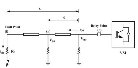
Fig.6 Fault distance calculation using two voltage dividers
From Fig.6, the voltage at the relay point (n) is given by

Substituting (6) into (4) yields

The fault distance (x) is given by

where V(r)and V(f)are the voltages at the reference sensor and fault point, respectively.R and L are the line parameters.For solid faults, Rf=0 and V(f)=Rf×i(f)=0, so the two voltage dividers arrangement can locate the fault accurately.However, this protection scheme only considers fault location rather than the fault detection process.For high resistance fault cases, the fault distance estimation may not be accurate, and the distance calculation in this protection scheme also takes a long time.
Reference [61] proposes a solution to the remote end fault in the two-terminal bipolar HVDC transmission line shown in Fig.7.In this method, the distance protection considering frequency dependent parameters is taken to evaluate the fault distance in the HVDC line since the inductance (L) of the transmission line is mainly dependent on the frequency.As shown, the distance relay is located at the point M, while Vmand imare the voltage and current measured at the relay location (M), and Vkand ikare the voltage and current at the setting point (K).The accuracy is dependent on the criterion given in (9), while the allowable error vs fault distance is shown in Fig.8.
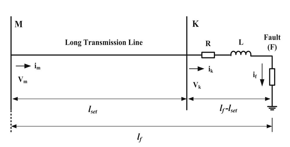
Fig.7 Transmission line model under fault(F) condition

Fig.8 Allowable error vs fault distance

where Eris the measurement error, lfand lsetare the fault and setting distances, respectively.The allowable error (lf−lset) is the difference between the fault distance and setting distance.Higher accuracy is very important since there is a very small allowable error when the fault occurs near the setting point K.The measurements are taken at the setting point (K) with the help of the frequency dependent parameter line model.
The voltage at the setting point and the criteria to identify the fault are given by.

However, the accuracy of this protection scheme may be affected by the reduction of allowable error to a very small value when the fault occurs near or at the setting distance or point.
3.6 Wavelet transform based methods
In the past, Fourier transform (FT) was used to extract the spectral components of a signal, but it provides the frequency components in the signal with no time information.Thus, it is not suitable for non-stationary signals which are very important for the protection of an HVDC transmission line.Short time Fourier transform (STFT)was later used to extract the spectral contents of the signal which provides the existing frequency bands and corresponding time intervals, i.e., the resolution is fixed.However, it does not provide the information of the existing frequency at the time instant.Therefore, the wavelet transform (WT) is used to extract the transient signals due to faults and other disturbances.WT is a powerful tool in the signal processing methods for tracking the fault transients in non-stationary signals [62–66].The continuous wavelet transform (CWT) of a signal f(t)is given by

The protection scheme based on WT can be seen in[67–71].References [42] and [44] use WT to detect the traveling waves and voltage transients for the detection of a DC fault in HVDC line.In [72], WT is applied to identify the DC fault in the MT VSC-HVDC system using local measurements, where the DC voltage,current, and their derivatives are used as the wavelet coefficients, and the triple modular redundancy (TMR)is used to achieve the selectivity.In [73], the fault current rising time is captured using WT to detect the fault in the HVDC system.In [74], the complex WT is used to extract the characteristic and non-characteristic frequency current for the fault detection in an MTDC line.In [75], WT is used to extract the high-frequency transient of the cable sheath voltage to detect the fault in a VSC-HVDC line.References [76] and [77] use the discrete WT to track the high-frequency transient signals for locating the fault in the MT HVDC system.In [78], the boundary discrete WT based overcurrent protection for the IEEE 30 bus distribution system with distributed generation (DG) is presented, and the simulation results are compared with the conventional FT based overcurrent protection.
However, in the WT based protection methods, the wavelet coefficient is predefined for the fault detection.The fault inception angle and fault resistance can influence the effectiveness of the wavelet co-efficient-based protection scheme.In addition, it may not be suitable for a stand-alone protection method.
3.7 Transient based protection methods
In [79], the difference in transient energy between the rectifier and inverter ends is used to detect and discriminate between the internal and external faults in a two-terminal HVDC line.The two-terminal HVDC transmission system is shown in Fig.9.

Fig.9 Two-terminal HVDC transmission system
The relay is located at the rectifier side (M) and inverter side (N) of the line and it uses the DC voltage and current measured at both sides to calculate the difference of the transient energy.It is calculated based on the transmission line equations within the consideration of a distributed parameter model.
The variation of transient energy (ΔE) can be calculated by

where ΔuM, ΔiM, ΔuN, ΔiNare the variations of the DC voltage and current at the rectifier and inverter sides.Δt is the continuous period from t1to t2.The variation of transient energy (ΔE) is zero under normal conditions,but has a certain value if a fault occurs in the HVDC system.An internal fault occurs when |ΔE|>ΔEsetand ΔE<0 while an external fault occurs when |ΔE|>ΔEsetand ΔE>0, where ΔEsetis the setting of threshold value for the variation of transient energy.However, the transmission line length and fault resistance can affect the accuracy of the protection scheme.
Fault detection based on the high-frequency transient signal extracted using WT is presented in [42].In[80–82], the non-unit protection scheme, which is the combination of starting, boundary, directional and faulty line identification units is proposed and tested in the hardware.The starting unit uses the voltage gradient to differentiate the abnormal state from the normal condition, while the boundary unit based on energy calculated from high-frequency transient signal is applied to distinguish the internal and external faults.The directional unit uses the forward and backward traveling waves to detect the direction of the fault.Since the transient energy of the faulted line has a higher value than the normal lines, the faulty line identification unit uses the comparison of the transient energy generated in the HVDC line.
Reference [83] uses the transient harmonic current to detect and discriminate between the internal and external faults in a two-terminal HVDC line.The transient harmonic current is low in the case of an external fault since it is limited by the DC filter and smoothing reactor, but it has a high value for an internal fault.Hence, the calculated difference of the transient harmonic current at both sides is applied to differentiate the internal fault from the external fault.However, the sensitivity of this protection scheme is affected by the fault resistance and location, and it requires both side information to make the decision.In [74], fault location is achieved using the characteristics of DC filters in the MTDC line.The internal and external faults are distinguished using the current at the characteristic and noncharacteristic frequencies that are extracted with the help of a complex WT.An internal fault occurs when the characteristic frequency current is more than the non-characteristic frequency current; otherwise, it is considered as an external fault.
In [75], a novel fault location method based on the sheath voltage for a two-terminal VSC-HVDC system is reported.The sheath of the cable is grounded at each end of the HVDC substation, and the sheath voltages are measured at these points.Under normal conditions, the transient voltage in the cable sheath is zero, and no current flows through it.However, in a fault situation, the transient voltage of the cable sheath has a certain magnitude and the fault current also flows through it.Therefore, the transient voltage of the cable sheath is used to identify the fault, and the signs on both sides are applied to discriminate between the DC fault and capacitor unbalance.Reference [76] uses the difference of the energy index which can be calculated from the high frequency transient current signals measured at both ends to detect the DC fault in the MT VSC-HVDC systems.In [77], the high-frequency transient signal at one terminal is used to identify the fault, and the internal and external faults are distinguished by the shunt capacitor connected at the bus bar.This eliminates the high-frequency transients coming from external faults.Although the shunt capacitor increases the cost, it can reduce the communication system requirement since it uses only one end measurement to make the decision.
However, in real time, accurate fault detection may not be possible by capturing only the fault induced transient signals since the switching and other transient events can also generate similar transients.
3.8 Voltage and current derivatives based methods
Reference [84] presents a voltage derivative (dv/dt) and current derivative (di/dt) based protection scheme for the MTDC system using the single end measurements.The fault can be identified if the rate of change of DC voltage and current exceeds the preset threshold.In[85], the fault detection in an earthed HVDC grid is presented based on the rate of change of voltage (ROCOV).The DC inductor is connected in series with the DC breaker to control the peak fault current to be below the breaker’s current rating.Figure 10 shows the proposed fault detection method using the ROCOV and current limiting inductor.Where Vbusis the voltage at the bus terminal, VLthe voltage across the inductor, and Vlinethe voltage on the transmission line or cable side.
The inductor voltage is given by

From Fig.10, the voltage at the bus terminal is given by
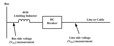
Fig.10 Illustration of fault detection method

Substitution of(18) into (16)yields

where L is the inductance value.If the fault occurs in a line, Vbusis constant for the first few milliseconds, and the rate of change of current (ROCOC) at the breaker is mainly dependent on the line side voltage (Vline).Therefore, the fault location can be achieved by measuring the ROCOV on the line side of the limiting inductor.The variation range of ROCOV can be used to distinguish the different zone and bus faults by setting the preset threshold values.In addition, the rate of rise of the fault current can be limited by increasing the inductor value connected in series with the breaker.However, it assumes that the DC voltage of the converter output is constant after the fault.In [86], the variation range of the DC reactor voltage is used to detect the fault in meshed MT HVDC systems.The changes in the DC reactor voltage are observed continuously and compared with the preset threshold value to identify the fault.However, the setting of the threshold value for the protection scheme is challenging for the purpose of discriminating between the different zones or line faults and high resistance faults.
In [87], the non-unit protection scheme for a DC fault in the MT VSC-HVDC grid is presented, where an inductive termination determines the protection zone.It applies under-voltage detection to identify the fault, and the threshold value for the under-voltage criterion is set at 85% of the rated DC voltage.After fault identification,the voltage and current derivatives are used to discriminate the first and second zone faults.However, the voltage derivative is vulnerable to close-up faults,measurement error, and noise, so the direction of the current derivative is used to differentiate the forward and backward faults.However, discrimination of the Zone-1 high resistance fault from the Zone-2 solid fault becomes very difficult and the second zone boundaries are not considered in this paper.Also, the threshold setting for the fault discrimination criterion may not work properly when the fault resistance variation is significant.In [88], the first and second derivatives of the fault current are used to detect and discriminate the fault in the DC micro-grid.The calculation for an adaptive threshold setting of the protection scheme is presented since it is essential for considering high impedance faults and different operating conditions.
3.9 Circuit breaker and semiconductor device based methods
In this section, the recent development in the HVDC circuit breaker (CB) using power electronic components and its fault isolation methods are presented.Some converters used in the HVDC system can also isolate the fault event and therefore, the protection methods based on the power electronic converters are also discussed.
3.9.1 HVDC CB based protection
In [38] and [39], the handshaking method which uses AC CB and DC switches, is applied to locate and isolate DC faults in the MTDC system.The isolation of the faulty line in the DC system is much more challenging than in the AC system since DC current has no zero crossing.Various DCCB such as mechanical, solid state and hybrid CB are available to isolate DC faults and these are discussed in [6, 89–97] and shown in Fig.11.
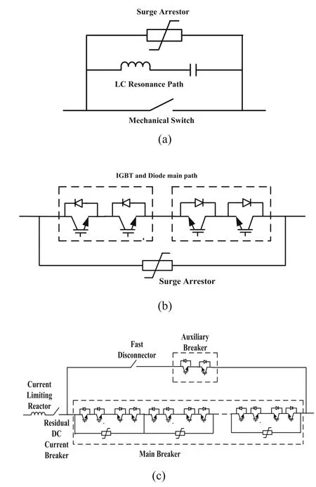
Fig.11 DCCB technologies.a Mechanical CB, b Solid state CB,c Hybrid CB
In[98–100],the mechanical DCCB is applied to isolate the fault in a high power DC grid.The mechanical DCCB shown in Fig.11 (a) achieves fault current zero crossing using the LC resonance circuit.It is suitable for CSC-based HVDC systems and has the advantages of low cost and on-state losses.However, the total operating time for the mechanical DCCB is around 30–100 ms which makes it unsuitable for VSC HVDC grid applications.It can provide a satisfactory solution for the protection of an HVDC grid when it is operated with the fault current limiters (FCL), though the cost of fault current limiters is high.In [101], the slow speed protection is achieved in a DC grid using the fault tolerant two-level VSC which controls the fault current within the safer limit until the mechanical DCCB isolates the faulty line.The operating time of the mechanical DCCB is considered as 60 ms with the peak interrupting current of 9 kA.However, the interruption current is too high for a specified trip time when the fault occurs away from the VSC terminal.Also, it is suggested that a fast interruption device is required for a weak AC grid as it will not allow such high fault current for a long duration.The optimization of the size of the inductor,capacitor, surge arrestors and switching arcs, and developing fast-mechanical switches in the CB can be considered as areas for further research [6, 97].
The use of semiconductor devices such as IGBT and insulated gate commutated thyristor (IGCT) in DCCB has increased due to the requirement of fast DC fault current interruption [91, 92, 94, 102].The schematic diagram of the solid-state DCCB can be seen from Fig.11 (b).Under normal condition, the DC current flows through the semiconductor switch path and the IGBT switches will block the fault current once the fault is detected and the surge arrestor is used to protect the CB switches from overvoltage due to the sudden blocking of the IGBTs.It can interrupt the fault current very quickly and the typical operating time of the solid-state DCCB is less than 1 ms.Thus it can be applied where high speed fault isolation is required.However, it increases the losses during normal conditions and the cost of the CB device is high.Wide bandgap semiconductor materials such as diamond, GaN,and SiC which have high breakdown strength and low losses can be alternatives for the IGBTs in such CB devices[6].
The hybrid DCCB combines the advantages of the mechanical and solid-state CB as shown in Fig.11 (c).The operation of the hybrid DCCB and its application to HVDC grid are presented in [94, 97, 103–106].In the hybrid DCCB, the auxiliary breaker and fast metal contact disconnector create a path for the normal DC current to flow.The auxiliary breaker has a small number of semiconductor switches resulting in low on-state losses.Under normal conditions, no current will flow through the main breaker path.When a fault occurs in the system, the auxiliary breaker switches off the IGBTs and commutates the fault current to the main breaker and the mechanical fast disconnector isolates the auxiliary breaker.The main breaker then opens to completely isolate the fault.The hybrid DCCB can provide high-speed fault isolation because of the use of semiconductor switches, and its operating time is 2 ms.Because of the small number of switches in the auxiliary breaker, it has lower losses during normal conditions than with the solid-state CB.In [107], the hybrid DCCB based fault isolation method for an HVDC grid is presented.In the hybrid DCCB, the size of the surge arresters and power electronic devices are dependent on the total protection time and peak breaking current.Reference [107] describes that fault in a particular location can be transferred to the whole HVDC grid because of the low impedance, and it suggests that the hybrid DCCB is cost effective for simple HVDC systems, but needs a very challenging communication system when applied to complex HVDC grids.
ABB and Alstom have tested the hybrid DCCB devices with a maximum breaking current of 16 kA and operating time of 2 ms [85, 103].The total protection time topis the combination of the time required for the fault detection and isolation,and the line transport delay from the fault point to the relay location is

where tbis the hybrid DCCB operating time, tdis the fault detection time, and tlis the line transport delay.d is the line length, v is the propagation speed of the traveling wave, c is the speed of light in a vacuum, n is the refractive index, and l and c are the line parameters[108–110].The DC fault current has high transients and may exceed the capacity of the hybrid DCCB if the total protection time is long.Therefore, current limiting reactors (CLR) are designed and connected in series with the hybrid DCCB to ensure that the DC fault current is within the breaker’s capacity.The DC reactor value can be calculated by

where Ldcis the DC reactor value, ΔV is the DC reactor voltage, andis the rate of change of the DC fault current [85, 111–115].Therefore, the hybrid DCCB with the combination of CLRs can be a good option for fault isolation in an MT VSC-HVDC grid.Further research could concentrate on the development and testing of the fast-mechanical switches and on reducing the on-state losses in the hybrid DCCB for high voltage and high current applications.
3.9.2 Power electronic converters based protection
In [116] and [117], a unit and overcurrent protection scheme for the MTDC distribution system is presented using the new semiconductor devices embedded with converters to limit and interrupt the fault current.In the converters, the controlled switches such as emitter turnoff device(ETO)and IGBT are used in place of the antiparallel diode so as to block the fault current.This method can improve the control and current rating of the converter switches,and no extra protection devices are required because the converters are able to protect the HVDC line.However, in the case of a permanent fault, all the converters have to be shut down leading to the complete interruption of power transfer in the MT VSC-HVDC systems [118].Also, this method increases the total cost and losses and requires a complex control system.
An application of DC-DC converters for the HVDC grid is presented in[119–121].Power electronic switches and DC-DC chopper-based fault isolation methods are proposed to interrupt the fault current in the highpower DC grids [100, 107].The half-bridge and fullbridge DC-DC chopper-based breaker arrangements are shown in Fig.12.They can isolate the fault in microseconds, step-up or step-down the voltage level, regulate the power, and require no surge arrester.From Fig.12(a), the half-bridge DC-DC chopper cannot isolate the fault on the high voltage side.In comparison, the fullbridge DC-DC chopper as shown in Fig.12 (b) can interrupt the fault on the HV side, though it requires more switches which will increase the cost and control complexity.As the switch S4only operates when VLV>VHVand current flow is towards VLVit has limited use for HVDC applications, and a new DC-DC chopper topology is proposed as shown in Fig.12 (c) [107].It reduces the number of IGBT switches and the control logic, resulting in lower cost and losses.In [122], the new DC-DC chopper based on one- and two-switch topologies for fault isolation in HVDC line is proposed as shown in Fig.13.It uses fewer switches so the control system is less complicated, and the cost and power losses are reduced when compared to the existing methods in Fig.12.In addition, the simplified topology as given in Fig.13 (b) can be operated for unidirectional power flow.The advantage of the DC-DC chopperbased fault isolation method is that there is no need for communication across the whole HVDC grid.Also, the rate of change of fault current is lower than the hybrid DCCB because of the converter chopping action [107].However, the DC-DC chopper might not be suitable for the high power HVDC grid because of the required number of switches in the converter and at the operating frequency [123,124].
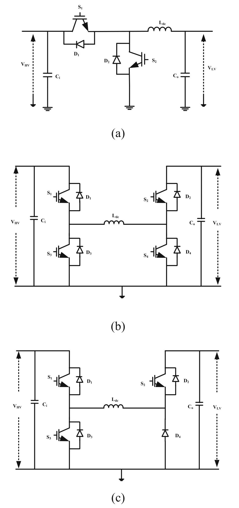
Fig.12 DC-DC chopper-based fault isolation method.a half bridge, b conventional full bridge, c proposed topology as given in [107]

Fig.13 Proposed DC-DC choppers as given in [122],a Two switch topology, b One switch topology
References[100, 107, 124–126] apply resonant DC-DC converters for fault isolation and high-power transfer in the DC grid.They are implemented based on the LCL thyristor-based converter which consists of two resonant LC circuits connected with a common capacitor as shown in Fig.14 [107].It can isolate a DC fault event while the healthy lines in an HVDC grid experience only the load rejection.During step-up condition, the thyristor switch pairs S1-S2and S5-S6are operational, while the switch pairs S3-S4and S7-S8are employed during step-down condition.It can change the power direction by changing the directions of both side current flows and provides better power regulation than the DC-DC choppers.However, the switching and conduction losses of the LCL thyristor-based converter are high, as is the harmonic pollution.It also requires a larger number of switches than the DC-DC choppers.
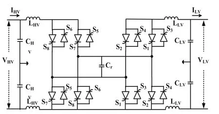
Fig.14 LCL thyristor-based DC-DC Converter
The limited number of voltage levels in the two-level VSC result in high AC current harmonics.Therefore,the modular multilevel converter (MMC) is now being used in HVDC systems since its many voltage levels result in fewer harmonics, lower switching frequency,and higher efficiency [127–131], compared to two-level VSC.The schematic representation of a three-phase MMC topology and its submodule blocks is shown in Fig.15.The half bridge MMC (HB-MMC) has fewer switches and lower losses than the full bridge MMC(FB-MMC).However, it does not interrupt the DC fault current because the fault current will flow through the antiparallel diode path, whereas the FB-MMC has an inherent capability to interrupt the DC fault current.In[132–134], the diode freewheeling phase during a DC fault is removed by using the single and double thyristor switches in an HB-MMC-based HVDC system to create a path for the DC fault current to flow.However, the rating of the bypass thyristor switches should be taken as the full short-circuit current.
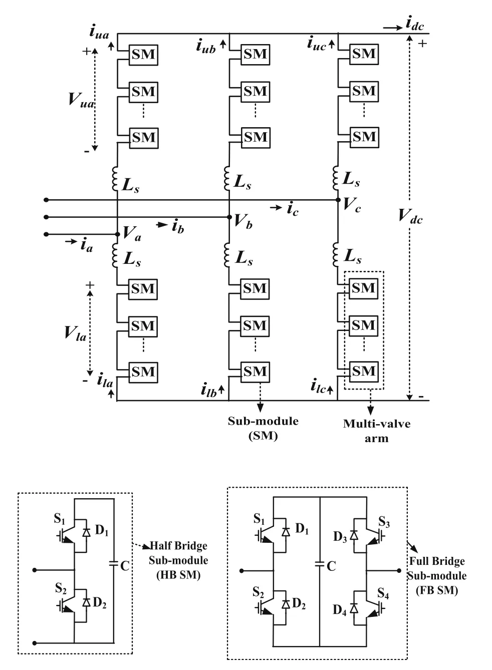
Fig.15 Typical three-phase MMC topology
In [135–137], an alternate arm converter (AAC)which is the combination of FB submodules (SM) and the director switches is applied for DC fault protection.The director switches consist of HV seriesconnected IGBTs.The AAC can block the DC fault current with fewer switches than the FB-MMC.However, the director switches require large numbers of IGBTs, while the flexibility of the AC voltage is restricted and a DC filter is necessary to remove the 6th harmonic in the DC current.In [138–140], a hybrid converter which combines the two-level VSC and cascaded FB SM is presented.It can block the DC fault current and provide AC fault ride through (FRT)capability.However, the active switches in the twolevel VSC have HV stress, and the synchronization of the two power stages (i.e., the two-level VSC as the main power stage and cascaded FB SM as the low power stage) is challenging.In [141, 142], the hybrid cascaded MMC (HC MMC) which is the combination of half bridge and cascaded full bridge cells is applied to block the DC fault current in the HVDC transmission system.Here, the HB cells are used in the main power stage.This will generate the voltage with low switching frequency and losses.The cascaded FB cells have DC fault current blocking capability and also reduce the harmonics generated by the main power stage.In HC MMC topology, the capacitor voltage balancing and synchronization of the two power stages are achieved, and the FB cells can eliminate the inrush current coming from the AC side during the deblocking action of converter after the fault event.
However, in the case of an MMC-based DC fault isolation method, a high number of IGBT switches are required and this will increase the cost when compared to other semiconductor device-based protection methods.In the case of the MTDC grid, the unfaulty lines are also affected because of the tripping action of the converter switches.Consequently, it may need additional DCCB for individual DC transmission lines.
During a DC fault, the two-level VSC will act like an uncontrolled diode rectifier, and the fault current can rise to very high values which could exceed the rating of the semiconductor switches.In [101] and [143], an LCL fault tolerant VSC combining the two-level VSC and inductor-capacitor-inductor (LCL) is proposed as shown in Fig.16 to maintain the DC fault current below the rated value in high-power DC grid [101].
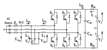
Fig.16 LCL fault tolerant VSC
In this method, the IGBT blocking action is not required since the converter can be operated with a very much lower fault current which is less than the rated current.The anti-parallel diodes of the VSC will also not be affected.Therefore, only a slow speed protection method using the mechanical DCCB is required for the DC grid with the LCL fault tolerant converters [101].It provides high reliability, low cost and losses when compared to the existing fault isolation methods.However,the power efficiency at partial load condition is reduced to 90% because of the increment of reactive power through the converter.In [144], the power efficiency at the partial load is improved to 97% at light load condition (about 0.2 per unit) by using switchable capacitor banks.However, the LCL fault tolerant converter is not recommended for weak AC grids (e.g., offshore wind farms) as the long fault interruption time is not acceptable.As per the references [108] and [109], the total time required for the overcurrent protection of the VSC (tVSC) can be calculated by

where tctris the delay of the VSC controller and tðI0→2puÞis the time required for the VSC current to reach the overcurrent threshold value.If the total protection time(top) as given in (21) is less than the overcurrent protection time of VSC (tVSC), i.e., tVSC>top, the MT HVDC grid will recover to normal operation after a fault.If tVSC References [145] and [146] present converter faults such as misfire, fire-through, flashover and DC link capacitor failure.A fire-through is the conduction of the switch before the scheduled instant of time, and its occurrence in the VSC can interrupt power transmission in the HVDC system.A misfire is the failure of a switch to conduct on the scheduled conduction period, while flashover occurring in the non-conducting switch can cause a short circuit and overcurrent in the converter.Short circuit or open circuit faults can occur in the DC link capacitor which can affect the performance of HVDC systems. Reference [147] analyzes the performance of differential and overcurrent relays on converter internal faults,and suggests that the location of current transducers for the overcurrent and differential relays should be modified.References [148] and [149] review the various protection methods for the VSC internal faults such as IGBT open circuit fault, short circuit fault and misfiring faults. Reference [16] analyzes the impact of internal faults of VSC for both grid side and rotor side in the DFIG based wind energy conversion systems.The open circuit faults on the DC link capacitor and misfire operation have less impact on the dynamic performance of the system than those of flashover and short circuit faults on the DC link capacitor and fire-through.It may be necessary to disconnect the wind energy system from the grid to avoid major failure in the converter switches which could affect the LVRT capability of the system.In addition,reference [16] proposes a method to detect the fault using voltage and current sensors.After the voltage and current measurement, the active power is calculated based on the measured values and is used to differentiate between a fault in the DC link capacitor and an IGBT short circuit fault since the active power variation is higher in the case of a short circuit fault in the DC link capacitor.Reference [133] presents the protection scheme for a DC link fault in the MMC based HVDC system using double thyristor switches.In this protection scheme, the double thyristor switches allow the DC link fault current to freely decay to zero since they eliminate the diode freewheeling phase in the MMC during DC link faults. ▪The development of a faster protection scheme is very important due to the high fault current [150].The fault transient signal is mainly dependent on the converter topology (i.e., both two-level and multilevel)and its control system, DC capacitor, and cable or transmission line model [151].Also,a fault current limiter may be applied to prevent damage to the HVDC components. ▪Double-ended protection schemes may not be suitable for the HVDC line main protection because of the long communication delay especially for long lines.A singleended protection scheme based on transients provides faster protection, and the DCCB can be operated with the current limiting reactor (CLR) to reduce the DC fault current [152,153].Also, more attention should be given to the optimization of the current limiting reactors considering cost and size reduction. ▪Further research on increasing the capacity, reducing the operating time and system cost of DCCB is required [154].The application of a fault current limiter with DCCB to limit the rising rate of the fault current can be explored in the future [155]. ▪The protection scheme can be tested with all the fault cases such as the faults on AC side and DC side with low and high impedances, converter blocking and DC power reversal action to check the robustness of the protection system [156]. ▪The protection scheme used in the AC grid cannot be applied directly to the DC grid.DC grid protection demands high speed in terms of communication and protection decision,larger bandwidth, advancement in the relay coordination and breaker operation[157].Also,the standards such as the IEC 60255, IEC 60834,IEC 61850, IEC 61869 may be modified to protect the HVDC grid along with the AC grid. ▪A protection scheme based on wide area measurement systems (WAMS) for an MT HVDC grid needs to be investigated [158],while developing more robust methods for the protection of the DC grid is challenging. ▪A protection scheme based on MMC with DCCB can be a potential solution [159, 160].However, it will increase the cost and power losses.The development of cost-effective methods to protect the DC grid and coordination with the CB, other protection devices and converters is needed.Further research on optimizing the full-bridge converter blocking action under DC fault condition is required[161].Suitable protection algorithms need to be developed to differentiate temporary faults from permanent DC faults to reduce the downtime of DC grid operation. ▪The protection of a large HVDC network is still a challenge, and has to consider the system level such as fault detection, DCCB, converter, real-time working condition and coordination with the operation of AC system while developing the protection scheme [162]. ▪Further research on the protection of the DC system has to be more concentrated because of the unavailability of the proper standards.The relay logic and CB device which are used in the AC system are not suitable for the DC systems since the characteristics of DC faults are different [163–165].A adaptive protection logic could work well because the HVDC system and high-power renewables are integrated with the AC system [165].It is recommended to develop the protection scheme with the consideration of the dynamic behaviour of high-power renewables to increase accuracy. Multi-terminal (MT) VSC-based HVDC systems have become increasingly popular in recent years.However,the development of a protection scheme for MT VSCHVDC systems is challenging since it is vulnerable to DC faults because of the small reactor and large capacitor on the DC side.In this paper, the characteristics of DC line-to-line and line-to-ground faults in VSC-based HVDC systems are presented, and the analysis of VSC internal faults and protection are discussed.DC faults can induce high fault current which is not tolerated by the semiconductor-based devices such as in the VSC,CB, and other HVDC components.Therefore, fast fault detection and isolation methods are required to protect the MT VSC-HVDC systems against DC faults. This paper presents a comprehensive review of various methods to protect HVDC transmission systems in the event of DC faults.The conventional protection scheme used in the AC grid such as distance, overcurrent, differential protections are not suitable for the HVDC grid protection since the characteristics of DC faults are different from the AC faults and other transient events.The traveling wave-based method can provide fast fault detection, but the detection of wave-head is the key challenge for identifying a DC fault in an HVDC line while the traveling wave is weak for high resistance fault cases.Wave-head detection is not required in the natural frequency-based method since it can use any section of the fault data to detect the fault.However, the extraction of the natural frequency is challenging under time-varying faults and transient conditions.The wavelet transform (WT) based method can be used to extract time-varying transients and provides fast fault detection.The wavelet coefficient is predefined for fault detection,while the fault inception angle and fault resistance can influence the effectiveness of the wavelet coefficientbased protection scheme.A hybrid approach combining wavelet transforms and traveling wave or natural frequency-based methods can improve the performance of fault detection in an HVDC grid. The single-ended transient based method can provide high-speed fault detection for a DC fault in an HVDC grid, though in real time, accurate fault detection may not be possible by capturing only the fault induced transient signals since switching and other transient events can also generate similar transients.The single-ended voltage and current derivative-based method also provides fast fault detection in an HVDC grid.However, the setting of the threshold value to discriminate the internal fault from the external fault is a challenge.In such conditions, the DC current limiting reactors can be used at the terminals of the HVDC grid to limit the voltage and current change rates.Therefore, the combination of the single-ended transient based method, and the voltage and current derivatives-based method with the current limiting reactors may provide a suitable option to detect and discriminate DC faults in an HVDC grid.However,the threshold setting which distinguishes the internal fault from the external fault may become problematic when the fault resistance variation is significant.In such a condition, the adaptive threshold setting can provide improved results. The development of a fast fault isolation method is very important because the total protection time is affected by the time required for the fault isolation process.Among the DCCB based fault isolation methods(i.e., mechanical, solid state and hybrid DCCB), the hybrid DCCB gives better performance with lower onstate losses than the solid-state CB and higher isolation speed than the mechanical CB.To prevent the DC fault current from exceeding the capacity of a hybrid DCCB,current limiting reactors can again be adopted so that the combination of the hybrid DCCB and current limiting reactors may be a suitable option for the fault isolation method in an HVDC grid.In addition, further research should be focused on the development and testing of fast mechanical switches and reduction of the onstate losses in the hybrid DCCB for high voltage and high current applications. Some power electronic converters (i.e., FB-MMC, DCDC converters) can isolate DC faults in the range of milliseconds.However they typically require an increased number of switches leading to higher cost, power losses and control complexity.In the case of an MTDC grid,healthy lines are also affected because of the converter blocking actions.On the other hand, the LCL-fault tolerant two-level VSC has the ability to operate the HVDC system even under DC fault condition by limiting the fault current within the rated value, although further research is required, e.g., on connecting to weak AC grids such as offshore wind farms. Abbreviations DC: Direct Current; AC:Alternating Current; HVDC: High Voltage Direct Current; HVAC: High Voltage Alternating Current; CSC: Current Source Converters; VSC: Voltage Source Converters; IGBT: Insulated Gate Bipolar Transistor; MTDC: Multi-terminal Direct Current; CLR: Current Limiting Reactors; WT: Wavelet Transform;FT: Fourier Transform;CB: Circuit Breaker;CWT: Continuous Wavelet Transform;LCC: Line Commutated Converters;TEO: Teager energy operator; STFT: Short Term Fourier Transform; TMR: Triple Modular Redundancy; ROCOV: Rate of Change of Voltage; ROCOC: Rate of Change of Current; FCL: Fault Current Limiter; MMC: Modular Multilevel Converter; HB-MMC:Half Bridge Modular Multilevel Converter; FB-MMC: Full Bridge Modular Multilevel Converter; AAC: Alternate Arm Converter;LCL: Inductor-Capacitor-Inductor; WAMS: Wide Area Measurement Systems Acknowledgements Not Applicable. Author’s contributions The author is performed the comprehensive review of DC fault protection methods in the HVDC transmission systems (for both CSC and VSC based HVDC systems and both two-terminal and multi-terminal HVDC networks).The DC fault protection methods include different fault detection,location and isolation methods have been explained.Also, the detailed study of the various DC faults are explained and its simulation results are presented.The authors read and approved the final manuscript. Authors’ information Mohan Muniappan (Corresponding Author),Senior Research Specialist, Center for Future Energy Systems (CFES),Rensselaer Polytechnic Institute (RPI),Troy, New York– 12180 E-mail: mohanbe.m@gmail.com Personal Website: https://sites.google.com/view/mohanmuniappan/home Funding Not Applicable. Availability of data and materials Not Applicable. Competing interests The author declares that the author has no competing interests.3.10 Converter faults and protection
4 Recommendations
5 Conclusions
 Protection and Control of Modern Power Systems2021年0期
- Protection and Control of Modern Power Systems的其它文章
- Application of a simplified Grey Wolf optimization technique for adaptive fuzzy PID controller design for frequency regulation of a distributed power generation system
- A critical review of the integration of renewable energy sources with various technologies
- Operational optimization of a building-level integrated energy system considering additional potential benefits of energy storage
- An integrated multi-energy flow calculation method for electricity-gas-thermal integrated energy systems
- Sliding mode controller design for frequency regulation in an interconnected power system
- Impact of communication time delays on combined LFC and AVR of a multi-area hybrid system with IPFC-RFBs coordinated control strategy
