Polyvinylamine-Based Facilitated Transport Membranes for Post-Combustion CO2 Capture: Challenges and Perspectives from Materials to Processes
Xuezhong He
a Department of Chemical Engineering, Norwegian University of Science and Technology, Trondheim N-7491, Norway
b Department of Chemical Engineering, Guangdong Technion Israel Institute of Technology (GTIIT), Shantou 515063, China
Keywords:Facilitated transport membranes Flue gas Hollow fiber CO2 capture Process simulation
ABSTRACT Carbon dioxide(CO2)capture by gas-separation membranes has become increasingly attractive due to its high energy efficiency, relatively low cost, and environmental impact. Polyvinylamine (PVAm)-based facilitated transport (FT) membranes were developed in the last decade for CO2 capture. This work discusses the challenges of applying PVAm-based FT membranes from materials to processes for postcombustion CO2 capture in power plants and cement factories.Experiences learned from a pilot demonstration system can be used to guide the design of other membranes for CO2 capture. The importance of module and process design is emphasized in the achievement of a high-performance membrane system.Moreover,the results from process simulation and cost estimation indicate that a three-stage membrane system is feasible for achieving a high CO2 purity of 95 vol%. The specific CO2 capture cost was found to significantly depend on the required CO2 capture ratio, and a moderate CO2 capture ratio of 50% presented a cost of 63.7 USD per tonne CO2 captured. Thus, FT membrane systems were found to be more competitive for partial CO2 capture.
1. Introduction
In order to combat the serious environmental issue of global warming, the reduction of greenhouse gases (especially carbon dioxide, CO2) from power plants and energy-intensive industries(e.g., cement, iron, and steelmaking factories) should be implemented [1]. Different CO2capture technologies such as postcombustion, pre-combustion, and oxyfuel combustion, as well as CO2removal from industrial gases, have been designed and demonstrated [2]. Among them, post-combustion CO2capture is considered to be a feasible solution for retrofitting existing plants.At present, post-combustion CO2capture using chemical absorption with amine-based solvents is considered to be the most mature technology,and has been implemented at the large and full scales[3].Great effort has recently been put into the development of next-generation and advanced solvents that can reduce the energy consumption of the whole capture process. However, the relatively high environmental impact and high capital expenditure(e.g.,the absorber)still challenge the wide implementation of carbon capture. Several emerging separation technologies based on ionic liquid solvents [4,5], solid adsorbents [6-8], and chemical looping cycles (e.g., metal oxides) [9,10] have been developed for CO2capture with a potential cost-reduction benefit.Recently,there has been great interest in the development of solid adsorbents such as metal-organic frameworks (MOFs) [11] for CO2capture,as they present a higher CO2adsorption capacity and relatively low energy consumption compared with other sorbents.However,the relatively low selectivity of CO2/N2for solid sorbents hinders its upscaling [11]. Gas-separation membranes have already been used for air separation (Prism®from Air Products & Chemicals,Inc.),biogas upgrading(e.g.,Evonik SEPURAN®Green),and natural gas sweetening (e.g., SeparexTM, Cynara®, and Medal) [12]; such membranes are regarded as one of the most mature and promising options for CO2capture in comparison with other technologies including cryogenic separation, chemical looping processes, and adsorption[13].Great effort has been made in the membrane community to improve membrane performance for different CO2separation processes [14-18]. Special interest has been paid to the development of facilitated transport (FT) membranes made from polymers containing amino functional groups. These membranes present a high separation performance based on the extra FT contribution from the chemical reaction of CO2with the functional group [19-25]. Considering the commercialization of membrane technology for CO2capture, energy-efficient and low-cost membrane systems should be designed.Moreover,membrane materials should achieve long-term stability under exposure to the impurities of SO2and NOxin flue gas.At present,only a few types of membranes have been demonstrated at the pilot scale for CO2capture,such as the Polaris®membranes at Membrane Technology &Research, Inc. (MTR), fixed-site-carrier (FSC) membranes at Norwegian University of Science and Technology(NTNU)(licensed to Air Products and Chemicals, Inc.), and PolyActive®membranes at Helmholtz-Zentrum Geesthacht [1].
It should be noted that bringing membranes from the laboratory to pilot-scale demonstration is not straightforward and can easily take 10-15 years. For example, polyvinylamine (PVAm)-based FT membranes were initially developed in 2004 by coating a thin selective layer onto a flat-sheet polysulfone (PSf) support[26]. Since then, membrane performance has been continuously improved by the optimization of membrane-preparation conditions over ten years [19,20]. Several pilot demonstration systems have been tested in power plants [27] and cement factories[28,29] using plate-and-frame and hollow-fiber modules. Moreover,durability testing through exposure to high loads of SO2over 200 ppm was performed in real flue gas,and stable membrane performance with a CO2purity greater than 60 vol% in the permeate side over a long testing period was reported by Hägg et al. [29].However,the testing results from those pilot systems indicate that module design is crucial in order to utilize the whole membrane area effectively for gas separation. Important module parameters such as fiber diameter, fiber length, and packing density must be optimized in order for the design of a high-efficiency hollowfiber module based on mathematical modeling to be possible[30]. In addition to PVAm-based FT membranes, the membrane research group at Ohio State University(OSU)has reported a highly selective amine-containing FT membrane tailored for CO2/N2separation with a CO2permeance of 1450 gas permeation units (GPU,1 GPU=10-6cm3(STP)·(cm2·s·cmHg)-1, in which STP means standard temperature and pressure, 1 cmHg=1.33×10³Pa) and a CO2/N2selectivity greater than 150[31,32].It should be noted that their estimation of the gas permeance,which was conducted by fitting the experimental data using COMSOL Multiphysics®[32],might be overestimated, as the average driving force was significantly underestimated. Nevertheless, those FT membranes have been demonstrated to have good performance for CO2capture from real flue gas, although the cost of a full-scale process needs to be evaluated in order to document the technology advance.Thus, in this work, the status and challenges of PVAm-based FT membranes from materials to module and pilot-system design and testing are discussed, and a process feasibility analysis of a three-stage FT membrane system is performed to provide guidelines for designing an efficient membrane system for CO2capture from flue gases.
2. Facilitated transport membranes
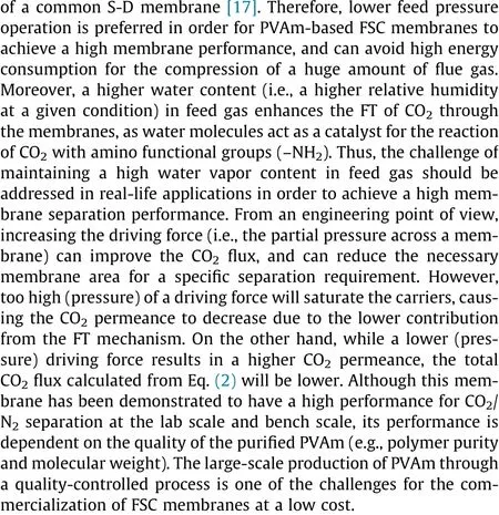
Flat-sheet FT membranes based on PVAm polymers were initially developed by the Memfo group at NTNU[33],and their good performance for CO2/CH4separation was reported by Kim et al.[26]. The influence of the molecular weight of PVAm was found to be significant for CO2permeation through membranes, and PVAm membranes with a higher molecular weight presenting a relatively low gas permeance due to the lower mobility of the longer polymer chains, but a much higher selectivity [26]. In general, those membranes presented a relatively low CO2permeance of 0.014 m3(STP)·(m2·h·bar)-1(1 bar=1×10⁵Pa). Later on,ultra-thin PVAm/polyvinylalcohol (PVA)-blend FT membranes were reported by Deng et al. [20], with a significantly improved CO2permeance performance (Fig. 1). Those membranes showed a good CO2/N2selectivity of up to 174 and a CO2permeance of 0.58 m3(STP)·(m2·h·bar)-1through mixed gas permeation tests at 2 bar and 25°C.It should be noted that the membranes were tested under humidified conditions, and the feed gas humidity was reported to have a great effect on the membrane separation performance [20]. In 2013, Kim et al. [19] reported that the pH of the casting solution had a significant influence on the performance of FT membranes, as the protonated amino group (-NH3+) does not contribute to the CO2FT. They successfully prepared benchscale membranes (30 cm×30 cm flat-sheet) from high-pH solutions, which presented a much higher CO2permeance of 5 m3(STP)·(m2·h·bar)-1at 1.1 bar. These high-performance PVAm-based membranes showed great potential for CO2capture from flue gas, and were tested in real flue gas [17,27-29]. Among them,a 4.2 m2pilot module was tested in real flue gas to document the dependence of the CO2flux on the driving force (partial pressure difference), as reported by He et al. [17]. Their testing results clearly indicated a significant FT contribution to the CO2flux, especially in the low feed pressure region (i.e., a low driving force). The CO2permeate flux, JCO2, is the sum of both the Fickian diffusion and FT diffusion, and can be expressed as follows [17]:
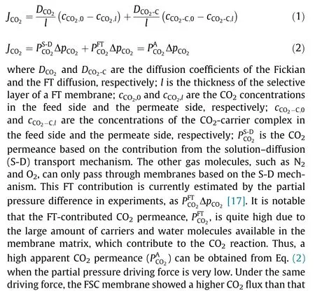
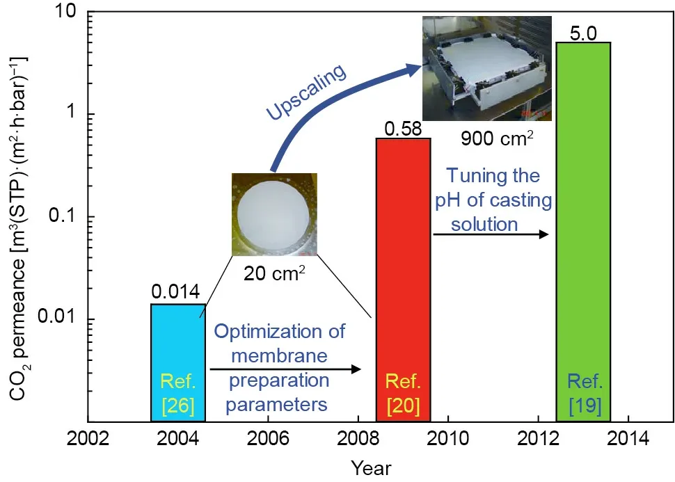
Fig. 1. Timeline of the development of PVAm-based FT membranes.
3. The challenges of membrane module upscaling
A plate-and-frame module (Fig. 2(a)) designed by Deng [34]was used for the lab-scale gas permeation testing of FT membranes.The cell is mounted with a circular cut membrane between its two parts, which forms a feed and a permeate gas chamber. A porous metal support is placed on the circular edge of the bottom of the support membrane, and a flat-sheet FT membrane is sealed with a rubbery O-ring.It is expected that the efficiency of this labscale module will be quite low due to its small effective membrane area based on a cross-flow mode. Moving the plate-and-frame modules from the lab scale to the small pilot scale is quite challenging, which is related to the sealing and gas distribution inside the module. A pilot plate-and-frame module (Fig. 2(b)) with a membrane area of 2 m2was designed by Yodfat Engineers for testing at the EDP’s power plant [27] and the Norcem cement factory[28].The pilot-testing results indicated that it was very challenging to achieve good gas distribution inside the module, and the effective membrane area was found to be much smaller than the estimated apparent membrane area. Thus, PSf hollow-fiber modules(provided by Air Products & Chemicals, Inc.) were introduced in order to reach high module efficiency with a counter-current mode.It should be noted that the in situ coating of PVAm selective layers on the PSf hollow fibers inside modules is quite challenging,as the coating procedure cannot easily be transferred from flatsheet membranes to hollow fibers. Nevertheless, 4.2 m2PSf hollow-fiber membrane modules (Fig. 2(c)) were finally successfully produced,and were tested for CO2capture from two different flue gases [17,29]. Even though the PVAm-based FSC membranes were found through testing to present a good performance at the pilot scale, further research work on controlling the quality of coated modules is still needed.
The space between hollow fibers is quite small, and has been estimated to be 0.82 mm based on a square pitch mode[17].Therefore,it is expected that uniformly coating PVAm thin layers on the outside of PSf hollow fibers is quite challenging, due to the high packing density. Inside coating may provide more uniform selective layers on the support. However, other support membranes are required, as the currently used PSf membranes (ultrafiltration MWCO 50 K)have their own outer selective layer,and the pore size of the inner layer is much too large,which makes it difficult to coat a thin PVAm inner layer without significant pore penetration.Moreover, for shell-side feeding, the experimentally measured pressure drops in the shell and bore side were 70 and 6.7 mbar,respectively, which indicated that the pressure drops for their hollow-fiber modules are quite low. It was also reported that the membrane module performance was not optimized, even though good membrane material performance was documented and was found to be comparable with the lab-scale testing results [17].
Mathematical modeling of a hollow-fiber module design was reported by Chu et al. [30], whose results indicated that the hollow-fiber inner diameter and length significantly influenced the pressure drop in the bore side. Moreover, the module packing density may have a great influence on the pressure drop in the shell side. It should be expected that the pressure drop for lowpressure operations (i.e., post-combustion carbon capture) will be much more significant than those for high-pressure scenarios(e.g., natural gas processing). A relatively low absolute pressure drop (e.g., 200 mbar) along the module length may cause a large reduction in the driving force,and thus increase the required membrane areas dramatically. Therefore, future work on designing energy-efficient modules without a significant pressure drop in both the feed and permeate sides is essential to improve module performance. A potential solution for reducing CO2capture cost could be the reduction of the required membrane area operated at elevated temperature with better-designed modules (e.g., to achieve higher gas permeance with the same selectivity); this is an engineering challenge for future work.
4. Pilot membrane testing examples
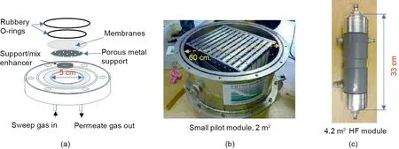
Fig. 2. Plate-and-frame modules at (a) the lab scale [34] and (b) the small pilot scale [27]; (c) a 4.2 m2 hollow-fiber (HF) module [17].
A tailor-made test rig was designed and constructed by the company of Yodfat Engineers,and was installed at Norcem’s Brevik site in January 2014 [28]. After an extended start-up phase, a six-month period of stable operation took place with a watersaturated feed gas by applying a humidifier in the feed line. The pilot system produced a high CO2purity of up to 72 vol%for a short period during which the whole system worked properly [28]. It was also reported that stable operation was more difficult to achieve than expected, the CO2permeate flux and purity were lower than expected,and the durability and other parameters were difficult to determine because of the relatively short time of the testing and other phenomena that influenced the testing [28].Therefore, a phase II project was launched in July 2015 to test a new pilot system using PVAm-based hollow-fiber membranes.Three modules with a total membrane area of 20 m2were installed in the pilot system using a compressor instead of a blower to provide flexibility for changing the feed pressure[29].Even though the compressor had a design capacity of up to 7 bar, the system was not tested at high pressures over 5 bar due to the expected high energy consumption needed for the compression of a huge amount of flue gas.Hägg et al.[29]reported stable membrane performance with a CO2purity greater than 60 vol%in the permeate side over a long testing period, as shown in Fig. 3(a). Moreover, another pilot system was tested for CO2capture from flue gas in a propane burner plant at Tiller (Trondheim, Norway), where the feed CO2content is much lower (ca. 9.6 vol%) [17]. That pilot system provided more flexibility through varying process parameters such as gas composition, feed flow, and operating pressure and temperature.Based on the testing results from these two pilot systems, PVAmbased membranes were found to be more economically feasible for CO2capture from flue gases with higher CO2content (e.g.,cement factories) than from flue gases with lower CO2content(e.g., power plants). Moreover, a membrane system that was operated at a relatively warmer temperature presented higher gas permeance without a significant loss of selectivity, as shown in Fig. 3(b) [17], which indicates that a moderate operating temperature is preferred for such a system. Future work on testing membrane systems at warmer temperatures is required to improve membrane system performance. However, maintaining a high water vapor content of the feed gas stream with no condensation in the whole system at a higher temperature is an engineering challenge. The key findings from the pilot testing [17,28] can be summarized as follows:
(1) Flue gas pretreatment units (e.g., particle filters and condensers) should be implemented to protect membrane units.
(2)Any water condensation inside a membrane system after the condenser/cooler should be avoided to protect all the instruments,controllers, and compressors, as condensed (acidic) water will result in serious corrosion of the hardware and reduce membrane performance and lifetime.
Her sisters burst out a-laughing, and began to banter42 her. The gentleman who was sent to try the slipper looked earnestly at Cinderella, and, finding her very handsome, said:
(3) A moderate operating temperature is preferred in order for an FT membrane system to function with high performance, if the membrane materials can tolerate a higher temperature.
(4)Design and optimization of the module and process are crucial to achieve high module performance in real-life applications.
Based on the pilot-testing results, the use of PVAm-based FT membranes for CO2capture from flue gas was evaluated at a technology readiness level (TRL) of 5 thus far; advancing to the next stage of a TRL of 6-7 with two-or multi-stage membrane systems should be further demonstrated before moving on to full-scale implementation. Again, process design related to inter-stage recompression and re-humidification should be thoroughly considered for this membrane. Moreover, a configuration using sweep gas instead of a vacuum pump might be applicable to reduce energy consumption.
5. Plant-scale membrane system design and simulation
5.1. Process description and simulation basis
Membrane systems are usually located downstream of the flue gas pretreatment units so that most of the impurities, such as SO2and NOx, are removed [35]. Flue gas pretreatment units (e.g., particle filters and condensers) should be implemented to protect the membrane unit. A flue gas containing 9.6% CO2/80.9% N2/5%O2/4.5% H2O by volume at a feed flow rate of 2.2×10⁵Nm3·h-1(Nm3means normal cubic meter) was simulated. In flue gas, all these gas species compete in the separation. High O2content in flue gas will make it challenging to obtain high-purity CO2, as CO2/O2selectivity is usually low (<10 [36]), and may be unable to achieve the purity requirement for CO2compression and pipe transportation. Water is crucial in most FT membranes, as it promotes the reaction with the neutral amino carriers, but too much condensing water may hinder gas transport through the membranes. Moreover, if the water permeance is too high, the membrane may become dry (with a very low relative humidity) and thereby less efficient toward the outlet in the retentate side.Thus,controlling the process conditions to maintain a high water vapor content in the feed gas through the whole membrane area is crucial.

Fig. 3. (a) Durability testing results of the pilot system [29]; (b) temperature influence of PVAm-based membranes [17]. NL: normal liter.
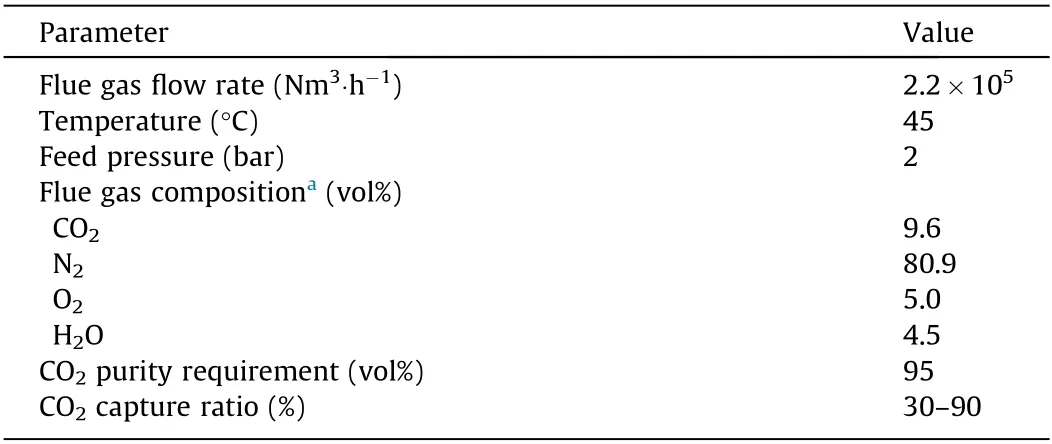
Table 1 Simulation basis.
It should be noted that no pressure drop was set for the heat exchangers/coolers, even though this is typically about 10 mbar per step. Any pressure drop would result in increased energy consumption by the compressors(e.g.,60 kW per step).However,this value is negligible,as a pressure drop of 200 mbar(bore-side feeding [30]) was set inside the membrane models, which has a dominating effect on the total energy consumption. All the simulations were conducted according to the simulation basis provided in Tables 1 and 2. It should be noted that a high vacuum operation (e.g., 200 mbar) in the permeate side will pull too much water through the membranes, so that many fewer water molecules will be available for FT contribution. This will result in a low CO2permeance (first-stage membrane) and low selectivity,compared with those during operation at a relatively low vacuum(e.g., 350 mbar) in the second- and third-stage membranes(Table 2). However, the CO2flux will be lower at a lower vacuum,which usually leads to a larger required membrane area.The water permeance was set to 10 times the CO2permeance for all simulations,which is higher than the tested H2O/CO2selectivity of 5 at a feed pressure of 2 bar [17]. A CO2purity of 95 vol% was set for either storage or utilization in the downstream processes. For example, the captured CO2could be compressed and transported to greenhouse plants and used as a liquid CO2source for a beneficial implementation of CO2capture technology. It is worth noting that pursuing a very high CO2capture ratio of greater than 90%will dramatically increase the CO2capture cost [37], and was not considered in this work.
5.2. Process design and simulation
In order to document the techno-economic feasibility of the PVAm-based FT membranes for post-combustion CO2capture, a three-stage membrane system (Fig. 4) was designed to complete the separation requirement. It should be noted that two-stage membrane systems with this membrane performance cannot achieve a CO2purity of greater than 95 vol%at a reasonable recovery. The flue gas (F1) was compressed to 2 bar and fed into the first-stage membrane unit to pre-concentrate the CO2. The CO2capture ratio was controlled by adjusting the membrane area using the ADJ-1 to adjust the stage-cut (where ADJ is the adjust unit in HYSYS and 1 indicates the first-stage membrane unit).The permeate gas of P1(i.e.,the permeate gas stream in the first-stage membrane unit) was then recompressed to 1.5 bar for further purification in the second- and third-stage units. The ADJ-2 was also used to control the CO2capture ratio, while the ADJ-3 was used to achieve the CO2purity requirement of greater than 95 vol%.It should be noted that the stage-cut is crucial in achieving the separation requirement in terms of both CO2purity and capture ratio [35]; it should be adjusted by tuning the process parameters and membrane areas.A permeate pressure of 350 mbar was set for the vacuum pumps of the VP-2 and VP-3 (Fig. 4).Moreover, a pressure drop of 200 mbar was set for each stage of the membrane system. The third-stage retentate (R3) was raised to 1.5 bar and recycled back to the second-stage feed, as the retentate CO2concentration in the third stage is higher than the feed of the second stage; doing this can achieve a higher CO2capture ratio when necessary.Even though controlling the water content in feed gas is important to maintain a high overall membrane system performance, re-humidification between membrane stages was not included in the simulation, as the humidifier cost is significantly lower than other major equipment costs. The following assumptions were made in the process simulations:
· The membrane performance obtained from Tiller pilot system[17] was used for simulation.
· The efficiency of the compressor, expander, and pump was assumed to be 85%.
· The counter-current configuration in ChemBrane was chosen.
·The membrane separation in each stage utilized a single membrane module with a pressure drop of 200 mbar.
Based on the gas-separation performance data(mainly gas permeance and selectivity) obtained from the lab- and/or pilot-scale experiments, the next step is to conduct process simulations to evaluate the techno-economic feasibility of the membrane system for post-combustion CO2capture at full scale.In this work,process simulations for CO2capture from flue gas were performed by HYSYS integrated with ChemBrane [38] to evaluate the required membrane area and energy consumption.Cost estimation was also conducted to evaluate the economic feasibility and to provide possible recommendations for further research and development.
5.3. Cost and footprint estimation model
A cost model reported in the literature was used for the estimation of the CO2capture cost in this work,and the major equipment cost of the compressors and membrane units was calculated based on the CAPCOST 2012 program[39]. Moreover, a membrane module cost of 35 USD·m-2was applied,considering the cheaper materials used for large-scale membrane production, while the membrane skid cost was estimated at a moderate price of 50 USD·m-2membrane surface area(this covers the cost for mounting the membranes into the module and pipe connection,but does not include pretreatment units or control instruments). A membrane lifetime of 5 years was estimated based on the pilot durability testing results.The annual capital related cost(CRC)was estimated to be 20% of the grassroots cost, which covers the depreciation,interest, and equipment maintenance (for a membrane unit, 30%is assumed, considering a short lifetime). It is worth noting that the cooling unit operation has a negligible influence on the cost and was thus not included. (Cooling towers are normally built in industrial plants(e.g.,power plants),and the cost of cooling water used in the membrane process is very small.)The operating expenditure(OPEX)was mainly estimated based on the electricity cost for the driving equipment. The specific CO2capture cost (USD per tonne CO2)was then estimated using the following equation:


Table 2 Membrane performance used for simulation.
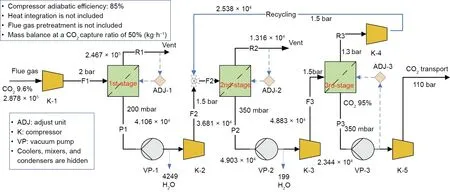
Fig. 4. Process flow diagram of a three-stage membrane system for CO2 capture.

Table 3 Key simulation results.
In order to estimate the footprint of this membrane system, a 40 ft container(12.2 m length)[29](inner volume of 67.5 m3)with a hollow-fiber module with a packing density of 2000 m2·m-3was employed.A factor of three was used to cover the manifolding and valves connection between modules,as well as the large header of each group membrane module. Therefore, an apparent module packing density of 700 m2·m-3for this type of container was employed.
5.4. Techno-economic feasibility analysis
Table 3 summarizes the key simulation results of the total power consumption for the compressors and the total membrane area for different CO2capture ratios ranging from 30% to 90%. It can be seen that an increase in the CO2capture ratio dramatically increases the required membrane area and total power consumption of the compressors.It should be expected that the incremental cost would not offset the increased CO2productivity.Therefore,the membrane system is more economically feasible for a scenario with a low-to-medium CO2capture ratio, which aligns with the results reported by Roussanaly et al. [37]. Moreover, the specific energy per tonne of captured CO2was found to be higher than the results reported in our previous work [29,40], which is mainly due to the relatively low gas permeance obtained from the pilot testing. Based on the obtained total required membrane surface area, the footprint of the membrane units was estimated to be 4-30 containers, which is acceptable, especially for the scenario with a moderate CO2capture ratio of 50%. It should also be noted that the operating pressure was chosen based on the pilottesting conditions in this work.
Process optimization cannot simply be conducted without experimental data under different testing conditions, as the FT membrane performance is operating-parameter dependent.Therefore, the process condition-dependent gas permeance should be obtained in future work,in order to investigate the technology feasibility of this membrane further.Moreover,it is worth noting that a CO2capture process is more challenging for flue gases with a high O2content, as the CO2/O2selectivity is quite low for the tested FT membranes. It should be expected that the impurity of O2in the captured CO2will be quite low, especially for the enhanced oil recovery (EOR) process. Therefore, a final purification with cryogenic distillation may be applied.
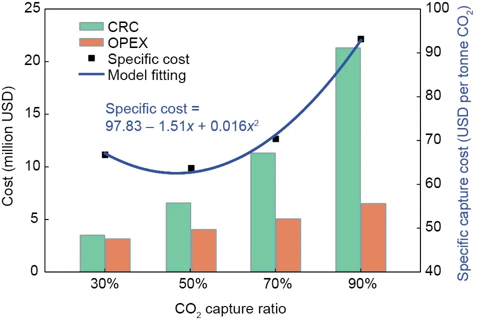
Fig. 5. Dependence of cost on the CO2 capture ratio.
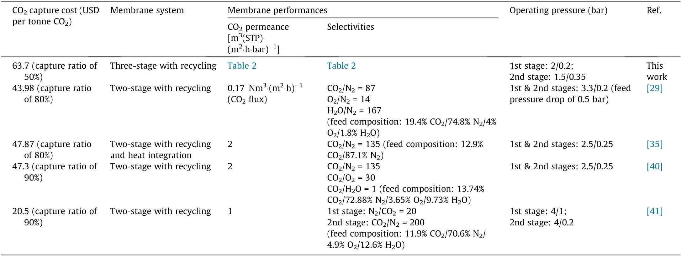
Table 4 Comparison of simulation results with the literature.
Based on the energy consumption and the required membrane area listed in Table 3, the annual CRC, operating cost, and specific CO2capture cost were estimated (Fig. 5). It was found that the specific CO2capture cost is significantly dependent on the capture ratio, such that pursuing a very high CO2capture ratio will dramatically increase the capture cost—especially the capital cost of the membrane units. Thus, it is recommended that a moderate CO2capture ratio should be applied to a membrane system for CO2capture. The specific CO2capture cost of 63.7 USD per tonne CO2captured was obtained at a capture ratio of 50% using the FT membranes.It was also found that the estimated CO2capture costs(63-93 USD per tonne CO2) were higher than the literaturereported CO2capture costs [35,40], as shown in Table 4. This difference is mainly due to the use of more realistic membrane performances (lower gas permeance and selectivity) based on fieldtesting under specific conditions. Moreover, Hussain et al. [41]reported the lowest CO2capture cost of 20.5 USD per tonne CO2by using two different membrane materials.It should be noted that N2/CO2selective membranes were still in an earlier research phase in the work of Hussain et al., and the selectivities of CO2over O2and H2O were not provided, which makes it difficult to compare the results. However, their reported membrane area of 6.9 × 10⁵m2was very close to the results obtained at a 70% CO2capture ratio in this work.It should also be expected that the high feed pressure of 4 bar used in their work requires higher operating and capital costs for the compressors. Therefore, their reported lower cost is probably due to the different cost models applied. It should be noted that the estimated CO2capture cost based on the pilot-testing results is still quite high,and is less cost competitive than amine absorption. However, the membrane material,module,and process performance can be improved to some extent by designing better modules and optimizing the process conditions—especially the uniformly coated modules and the operating temperature. Moreover, the designed three-stage membrane system can be optimized further by varying the operating pressure if membrane performances under other testing conditions are available. In addition, introducing sweep gas might be an option to reduce the energy consumption of the whole system.
6. Conclusions and perspectives
PVAm-based FT membranes were identified as a promising gasseparation membrane for post-combustion CO2capture. The high membrane material performance is attributed to the unique properties that come from the combination of the S-D and FT mechanisms. The challenge of in situ coating was identified for the upscaling of hollow-fiber FT membranes, which should be well addressed in order to control membrane repeatability.Future work on inside coating may provide FSC membranes with uniform and quality-controlled selective layers. Moreover, designing energyefficient hollow-fiber modules with lower pressure drops in both the shell and bore sides should be pursued to improve module performance. The PVAm-based FT membranes for CO2capture were evaluated at a TRL of 5 at present; advancing to the next stage of a TRL at 6-7 with two- or multi-stage membrane systems should be conducted before bringing this type of membrane into commercial application.However,process design related to inter-stage rehumidification should be thoroughly considered.
Based on the process simulation and cost estimation, it was found that PVAm-based FT membranes can achieve a high CO2purity of 95 vol% using a three-stage membrane system. The CO2capture cost was significantly dependent on the required CO2capture ratio.Pursuing a very high CO2capture ratio will dramatically increase the capture cost,which may result in a loss in the competition with state-of-the-art amine technology. Therefore, it is recommended to implement FT membrane systems for partial CO2capture. Although the CO2capture cost based on process simulation is still quite high, a future research focus on improving membrane system performance by the optimization of module design,process design, and operating conditions should be pursued, in order to enhance the competitiveness of membrane technology for post-combustion CO2capture.
Acknowledgements
The author acknowledges the Research Council of Norway for funding this work through the CO2Hing project (#267615) and Department of Chemical Engineering at Norwegian University of Science and Technology for conducting this work.
- Engineering的其它文章
- Application of the Chemical-Looping Concept for Azoetrope Separation
- Recent Advances in Electrode Design Based on One-Dimensional Nanostructure Arrays for Proton Exchange Membrane Fuel Cell Applications
- Membrane Crystallization for Process Intensification and Control:A Review
- Intermolecular and Surface Interactions in Engineering Processes
- Structural and Kinetics Understanding of Support Effects in Pd-Catalyzed Semi-Hydrogenation of Acetylene
- Comparative Study on Structural Redundancy of Cable-Stayed and Extradosed Bridges Through Safety Assessment of Their Stay Cables

