Recent Advances in Electrode Design Based on One-Dimensional Nanostructure Arrays for Proton Exchange Membrane Fuel Cell Applications
Shangfeng Du
School of Chemical Engineering, University of Birmingham, Birmingham B15 2TT, UK
Keywords:Proton exchange membrane fuel cell(PEMFC)Electrode One-dimensional (1D)Oxygen reduction reaction (ORR)Catalyst Ordered
ABSTRACT One-dimensional(1D)Pt-based electrocatalysts demonstrate outstanding catalytic activities and stability toward the oxygen reduction reaction (ORR). Advances in three-dimensional (3D) ordered electrodes based on 1D Pt-based nanostructure arrays have revealed great potential for developing highperformance proton exchange membrane fuel cells(PEMFCs),in particular for addressing the mass transfer and durability challenges of Pt/C nanoparticle electrodes. This paper reviews recent progress in the field, with a focus on the 3D ordered electrodes based on self-standing Pt nanowire arrays.Nanostructured thin-film (NSTF) catalysts are discussed along with electrodes made from Pt-based nanoparticles deposited on arrays of polymer nanowires, and carbon and TiO2 nanotubes.Achievements on electrodes from Pt-based nanotube arrays are also reviewed. The importance of size,surface properties, and the distribution control of 1D catalyst nanostructures is indicated. Finally, challenges and future development opportunities are addressed regarding increasing electrochemical surface area (ECSA) and quantifying oxygen mass transport resistance for 1D nanostructure array electrodes.
1. Introduction
Proton exchange membrane fuel cells (PEMFCs) can directly convert the chemical energy stored in fuels(i.e.,hydrogen)to electricity through a one-step electrochemical reaction with oxygen.This is a highly efficient clean energy conversion process, with water and heat as the only byproducts. Usually operating below 80°C,PEMFCs have an electricity efficiency of 40%-50%and a combined energy efficiency of 80%-95% if the generated heat can also be used(i.e.,in combined heat and power(CHP)units)[1].PEMFCs have the advantages of a solid-state-based compact design, quick startup and shutdown, and flexible power scale. The first PEMFC unit was developed in the 1960s at General Electric(GE)for spacecraft;it was then significantly improved in the 1980s and 1990s by introducing carbon supports for platinum (Pt) nanoparticle catalysts(Pt/C)and a proton-conducting ionomer into the catalyst layers, which dramatically reduced the Pt loading from about 4 to 0.4 mg Pt (mgPt) per square centimeter in electrodes, with enhanced power performance [2]. Today, PEMFCs have been successfully deployed as power generators in transport vehicles and buildings. According to the International Energy Agency (IEA)report Global EV Outlook 2020, the total sales of fuel cell electrical vehicles (FCEVs) in 2019 were 12 350, bringing the global stock to 25 210 units(including passenger cars,buses,and trucks).However,a high system cost and poor durability are still the two major challenges for PEMFC technology today(Fig.1(a))[3].The technology is still not competitive in comparison with conventional internal combustion engine (ICE) technology. Although FCEVs can be refilled at a much faster rate than battery electrical vehicles(BEVs)can be recharged, the relatively lower electricity efficiency and requirement of high-purity hydrogen limit the market expansion of this technology in comparison with that of BEVs. Among the PEMFC components, catalyst electrodes are where the fuel cell reactions take place. The catalyst electrodes determine the cell power performance and mainly define the system degradation rate. Furthermore, the catalyst materials and the process to fabricate electrodes make up more than half of the cost of the total fuel cell stack (Fig. 1(b)) [3].
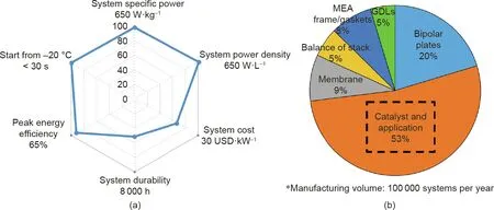
Fig.1. The status of(a)current PEMFC development and(b)stack cost breakdown.GDL:gas diffusion layer;MEA:membrane electrode assembly.Reproduced from Ref.[3]with permission of Papageorgopoulos.
Addressing the challenges of PEMFCs by developing new catalyst materials has been the hottest research topic for this technology in past decades, with a particular focus on catalysts to address the sluggish oxygen reduction reaction (ORR) at the fuel cell cathode [4,5]. Many excellent reviews have been published on the advances achieved in this area from both fundamental and application perspectives [6-12]. The latest generation of catalysts has been demonstrated to have extremely high catalytic activities[8,13], such as ultrafine jagged Pt nanowires, which record 52 times greater ORR mass activity compared with Pt/C nanoparticle catalysts in ex situ half-cell electrochemical measurement [14].For projections of the superior activities of this latest generation of catalysts into practical electrodes, many efforts have been focused on exploring new electrode approaches to bridge the gap between the pure materials research of these catalysts and high power performance fuel cells. Among these advances, threedimensional (3D) ordered electrodes—particularly those based on one-dimensional (1D) catalyst nanostructure arrays—have been significantly emphasized,due to their unique advantages in reducing mass transfer resistance and improving catalyst utilization to develop fuel cells for large current density operation at low catalyst loadings [15-17]. The basic designs of these approaches are schematically summarized in Fig. 2, categorized by the structure of the catalyst and its support, as well as by the electrochemical surface area (ECSA). The 3D ordered electrode based on jagged Pt nanowire arrays (NWAs) has the potential to contribute to a very high power performance, given the large ECSA of the catalysts,although this has not been achieved as yet.
In this review, progress achieved in novel 3D electrode approaches as cathodes toward ORR in PEMFCs is summarized and discussed in detail. It starts with a description of an ideal 3D electrode model, and then discusses nanostructured thin-film(NSTF) catalysts and nanoparticle catalysts deposited on 1D support arrays. Next, it provides a detailed discussion of the author’s group’s work with Pt NWAs. Finally, the use of self-standing Ptbased nanotube arrays (NTAs) is remarked. An extensive evaluation is performed on the relative improvements in ECSA and mass activities in electrodes,together with power density and durability in the membrane electrode assembly(MEA)test in single PEMFCs.
2.The concept of 3D ordered electrodes from 1D nanostructure arrays
In a conventional PEMFC electrode, the catalyst layer is constructed from randomly arranged Pt/C nanoparticles with protonconducting ionomer as both binder and ion transfer path.The electrode structure provides some porosity between the Pt/C nanoparticles for transferring reactant gases and generated water, as well as the carbon network for electron transfer and ionomer path for proton moving.For these three functions(gas transferring,electron conducting, and proton conducting), the active site is usually referred to as the triple phase boundary (TPB). Within the Pt/C nanoparticle electrode, this disorganized structure limits the charge and mass transport performance, which usually results in a low catalyst utilization ratio (usually below 30%) and restricts the large current density operation of fuel cells in practical applications. The challenges with the Pt/C electrode was very recently reviewed by Wang et al. [17].
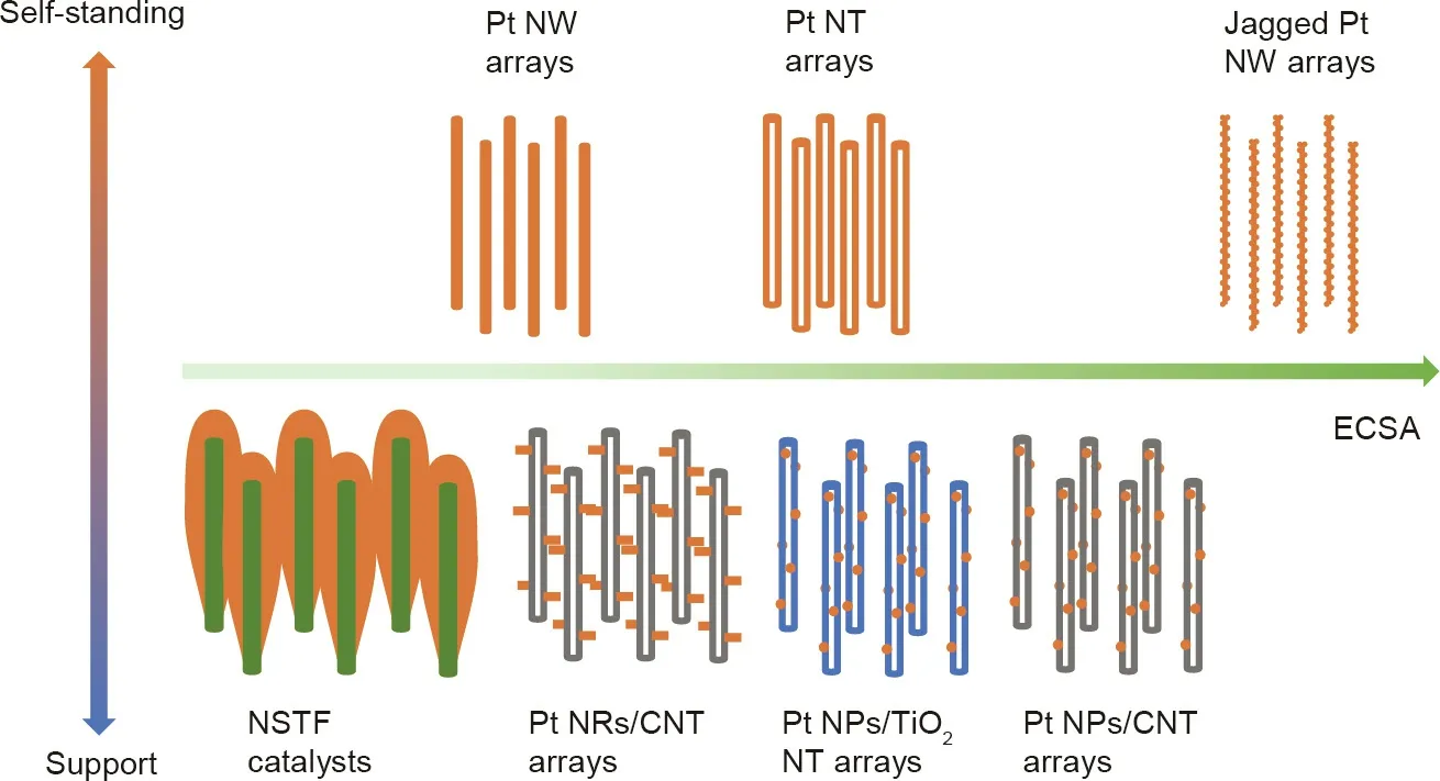
Fig.2. The basic designs of 3D ordered electrodes based on 1D catalyst nanostructure arrays.No jagged Pt nanowire arrays have been reported in the literature and they are included here to show the potential. NW: nanowire; NT: nanotube; NSTF: nanostructured thin-film; NR: nanorod; CNT: carbon nanotube; NP: nanoparticle.
In addressing the challenges of the Pt/C electrode, the concept of 3D ordered electrodes based on 1D catalyst nanostructure arrays has been developed with the purpose of achieving an extremely high degree of exposure of active sites and an efficient mass transfer path within a thin catalyst layer.An ideal model of this unique electrode structure, proposed by Middelman [18], is shown in Fig. 3. This type of electrode structure has been considered to be the most favorable approach to significantly improve the catalyst utilization ratio and power performance. It is expected that the electrode can be built with a vertically oriented electron conductor coated with catalysts and proton conductor, with through-hole structure. In recent decades, various electrode types based on 1D nanostructure arrays have been reported on Pt catalyst-decorated vertically aligned nanowires or nanotubes, or even self-standing 1D Pt-based catalyst arrays. Some of these findings, including our research on Pt NWA electrodes, were recently reviewed by a few researchers as part of the development of catalyst material[9,10,16,17]. Different from these material reviews, the present work provides a systematic review based on the electrode structure design in order to enable an understanding of the advances that have been achieved in this electrode approach and their potential contribution to PEMFC development.
3. 1D nanostructure arrays as catalyst supports
3.1. NSTF catalysts with 1D polymer structure array supports
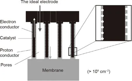
Fig. 3. Schematic diagram of an ideal 3D electrode based on 1D catalyst nanostructure arrays. Reproduced from Ref. [18] with permission of Elsevier Science Ltd., ©2002.
A famous electrode approach based on vertically aligned 1D nanostructures is the NSTF catalyst proposed by 3M Company.This catalyst electrode structure has been reviewed in many papers,including those by Debe [15,19]. It consists of a thin layer of polycrystalline thin film of Pt alloy(e.g.,PtCoMn or PtNi)catalysts(0.05 and 0.1 mgPt·cm-2at the anode and cathode, respectively) coated by magnetron sputter on vertically aligned perylene-based polymer whiskers.These whiskers have a cross-sectional area of about 55 nm×30 nm,a height of less than 1 μm,and a distribution density of 30-40 μm-2[20]. The catalyst layer thus achieves a thickness of about 1 μm, which is 10-20 times thinner than the conventional Pt/C nanoparticle electrodes with an equivalent catalyst loading, thus effectively enhancing the proton and electron transfer. Within this catalyst layer, the sputtered Pt alloy thin-film layer is made up of arrays of whiskerette-shaped nanostructures and has a thickness of 10-20 nm, which covers the entire surface of the whisker support.The Pt alloy catalyst surface is hydrophilic;thus, the space between catalyst whiskers is normally flooded with water during fuel cell operation, which can facilitate proton transport within the thin catalyst layer [21]. Therefore, the proton-conducting ionomer can be omitted from this NSTF catalyst electrode. During fuel cell operation, the ionomer can be contaminated by ions from the leaching of transitional metals(e.g., Co, Ni,Fe), which reduces its protonic conductivity and accelerates electrode degradation. With the NSTF electrode, the removal of the ionomer can thus also contribute to improving the fuel cell durability. However, this water flooding also accelerates the leaching of transitional metals from the alloy catalysts. Furthermore, the large size of the whiskerette-shaped catalyst structures results in a low ECSA ranging from 5 to 17 m2·g-1, which is much smaller than those of high-surface-area Pt/C catalysts [20], although this could be partially compensated for by a five- to ten-fold gain of the specific catalytic activity to achieve a reasonable mass activity.Another major consequence of the extreme thinness of the NSTF catalyst layer is water management issues caused by water flooding. At a given current density, the water generation rate per unit thickness within the NSTF cathode is 20-30 times higher than that of the Pt/C electrode proportionately thinner.This presents a major challenge for water management strategies. Both of these issues—the low ECSA and the severe water flooding—mean that many more efforts are required to put this promising NSTF technology into application.
Similar to the polymer whisker used in the NSTF catalyst,other conductive polymer NWAs,such as those composed of polypyrrole(PPy) and polyaniline (PANI), have been investigated as catalyst supports for Pt nanostructures. Benefiting from low cost, reasonable conductivity(in a partially oxidized state),good chemical stability and thermal conductivity, and enough simplicity to be fabricated into ordered nanostructures,such as nanowire or NTAs,PPy and PANI show excellent potential as electrocatalyst supports for PEMFC application. Jiang et al. [22] prepared electrodes from PtPd catalyst-decorated PPy NWAs.The PPy nanowires were grown on a stainless steel(SS) plate modified by Pd nanoparticles spaced about 60 nm apart.The PPy nanowire had a conical shape with an average length of about 1.1 μm, and exhibited an average bottom diameter of 120 nm and a top diameter of 80 nm.On the nanowire surface, catalysts were decorated by means of the physical vapor deposition(PVD)technique.The thin deposited PtPd catalyst layer showed whiskerette shapes along the PPy nanowires.The resulting structures were hot pressed onto a polymer electrolyte membrane(PEM) to make MEAs, in a similar approach as that used for the NSTF catalyst; similarly, no proton-conducting ionomer was applied.However,the MEA test(in H2/O2with a Nafion 211 membrane) recorded a lower peak power density of 0.762 W·cm-2(at catalyst loadings of 0.156 mgPt·cm-2and 0.0545 mg Pd (mgPd)per square centimeter at the cathode and 0.0846 mgPt·cm-2and 0.0528 mgPd·cm-2at the anode) compared with 0.846 W·cm-2for a Pt/C electrode (20% Pt/C; anode: 0.1 mgP-t2; cathode: 0.15 mgPt·cm-2).The ECSA deducted from the cathode cycle voltammetry(CV)analysis was only 5.67 m2per gram platinum group metal(PGM), which was ascribed to the large size of the PtPd whisker catalyst. Xia et al. [23] conducted a similar work to directly grow PPy NWAs on a carbon paper gas diffusion layer (GDL) substrate(Figs. 4(a)-(c)). Rather than using the PVD technique, Pt catalyst nanoparticles were decorated onto the NWAs using a wet chemical process. To obtain a uniform distribution of nanoparticles on the nanowire surface, the PPy nanowires were doped with Nafion proton-conducting ionomer during the nanowire growth process.The sulfonate groups in Nafion have an electrostatic interaction with the Pt cations, which enhanced their absorption onto the PPy nanowire surface. The Pt ions were then reduced with hydrogen at 250°C to form uniformly distributed Pt nanoparticles.The achieved Pt nanoparticles had an average particle size of about 4.3 nm (Figs. 4(d)-(f)). This unique electrode structure of Pt on Nafion-decorated PPy (Pt-NfnPPy) exhibited a peak power density of 0.778 W·cm-2in the MEA test under H2/O2at a catalyst loading of 0.065 mgPt·cm-2(as the cathode),which is comparable to that of a Pt/C (E-Tek) nanoparticle cathode with a loading of 0.198 mgPt·cm-2(Fig. 4(g)). The MEA was also tested under H2/air, and a slightly higher power density was observed for the Pt-NfnPPy nanowire electrode compared with a Pt/C electrode with three times the Pt loading(Fig.4(h)).The group also reported electrodes from PANI NWAs decorated with Pt nanoparticles and whiskerette nanostructures for PEMFC applications [24,25]. The PANI NWAs were first grown on the GDL surface using an in situ polymerization method.The length and diameter of the nanowires were controlled using the aniline monomer concentration and reaction temperature during the polymerization process. The obtained nanowires possessed an average diameter and length of 61 and 194 nm,respectively,with a distribution density of 78 μm-2.The electrodes were then prepared by either spraying Pt catalyst ink or sputtering Pt using the PVD method. In the case of PVD, the thickness of the deposited Pt catalyst layer is about 8.9 nm consisting of Pt crystalline nanowhisker arrays along the PANI nanowires,which is similar to the catalyst structures obtained by PVD in the NSTF catalyst and PtPd catalysts on the PPy nanowires in Jiang et al.’s work [22]. Although the Pt catalyst layer has a large size, when it is used as cathodes in PEMFCs, the boosted mass transfer performance within the NWA structure still led to a 11% higher peak power density (about 0.542 W·cm-2at a catalyst loading of 0.095 mgPt·cm-2, recorded in an MEA with an active area of 2 cm×2 cm,Nafion 212 membrane,at 70°C,under H2/O2without backpressure) than that of a Pt/C electrode (0.120 mgPt·cm-2, Pt/C 60 wt% from Johnson Matthey (JM)).
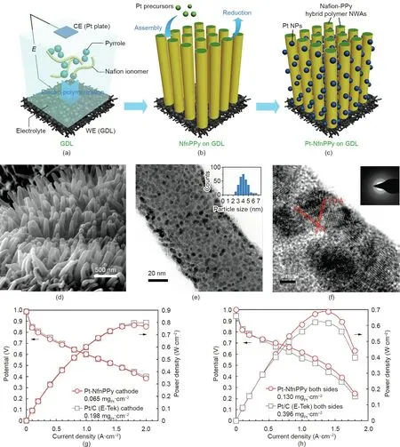
Fig.4. (a-c)Schematic illustration of the fabrication process for PPy NWA electrodes:(a)electrochemical polymerization to grow PPy nanowires;(b)Pt catalyst loading;and(c)MEA fabrication.(d)Scanning electron microscope(SEM)and(e)transmission electron microscope(TEM)images of Pt-NfnPPy nanowires in the electrode.The inset in(e)shows the Pt nanoparticle size distribution. (f) High-resolution transmission electron microscope (HRTEM) image with a selected-area electron diffraction (SAED) pattern(inset) of Pt-NfnPPy. (g, h) Polarization curves for MEAs with the Pt-NfnPPy and conventional Pt/C electrodes tested with fully humidified (g) H2/O2 and (h) H2/air at 70 °C(Nafion 212 membrane,MEA active area of 2 cm×2 cm,stoichiometry:H2 2 and O2/air 9.5/2,0.15 MPaabs).CE:counter electrode;WE:working electrode;NWA:nanowhisker array. Reproduced from Ref. [23] with permission of Springer Nature Limited, ©2015.
3.2. Pt nanoparticles on carbon nanotube and 1D TiO2 arrays
Based on the advantages of 1D nanostructure arrays,electrodes have also been developed by depositing Pt catalysts onto carbon nanotube(CNT)arrays.CNTs possess higher electrical conductivity and a larger surface area than polymer whiskers. The CNT array structure can also benefit from the vertically aligned structure,which enables better mass transport in practical electrodes compared with high-surface-area carbon particles. Better durability is also expected for CNTs, due to their higher resistance to corrosion in fuel cell operation.
A typical fabrication process for electrodes from Pt-decorated CNT arrays is shown in Fig.5[26].In general,CNT arrays are grown on a substrate surface (e.g., SS, SiO2, quartz, Al foil) with catalysts(e.g.,Fe or FeCo).Next,the whole or top part of the CNTs is coated with Pt nanoparticles by chemical or physical methods, followed by surface coating with proton-conducting ionomer. Finally, the substrate with Pt-decorated CNT arrays is decal transferred onto PEM by hot pressing. Zhang et al. [27] demonstrated electrodes based on CNT arrays (with an average height of 4 μm). In these electrodes, 4 nm Pt nanoparticles were deposited on the surface by controlling the chemical reduction of H2PtCl6solution using NaBH4. They reported a higher ECSA and nearly double power density compared with a Pt/C (HiSPECTM4000, JM) catalyst electrode in the H2/O2PEMFC test (78.72 to 52.22 m2·gP-t1), and 0.397-0.211 W·cm-2at 0.65 V,respectively,with 0.142 mgPt·cm-2on both the anode and cathode,Nafion 115 membrane,MEA active area of 5 cm2, cell temperature of 80 °C, and backpressure of 0.1 MPa). Tian et al. [28] reported a scalable approach to fabricate electrodes with Pt-coated CNT arrays by combining plasmaenhanced chemical vapor deposition (PECVD) and physical sputtering. Arrays of CNTs with an average length and diameter of about 1.3 μm and 10 nm, respectively, were grown on Al foil. Pt nanoparticles were deposited using the physical sputtering method, achieving a depth of about 200 nm along the CNT arrays.The electrodes with various catalyst loadings were tested as cathodes in single cells(Fig.6)[28].With a Pt loading of 0.05 mgPt·cm-2,the Pt/CNT array electrode exhibited a peak power density of 0.73 W·cm-2compared with 0.41 W·cm-2for a Pt/C electrode(JM Pt/C, 40%) in the H2/O2PEMFC test. However, this advantage was lost under a high catalyst loading. For the Pt/CNT array cathode with 0.118 mgPt·cm-2, the peak power density dropped to 0.69 W·cm-2, which is even lower than 0.8 W·cm-2of the Pt/C cathode with 0.1 mgPt·cm-2. This demonstrates the limit of using nanoparticle catalysts to decorate CNT array structures for fabricating catalyst electrodes.It is difficult to achieve high nanoparticle catalyst loading in practical electrodes without causing aggregation, which will have a negative influence on fuel cell power performance. Further development of Pt/CNT array electrodes includes the growth of ultrafine CNT arrays and the deposition of uniformly distributed extremely small Pt nanoparticles [26,29-31]. Some of these works have been summarized and discussed in a recent review paper by Van Hooijdonk et al. [32].
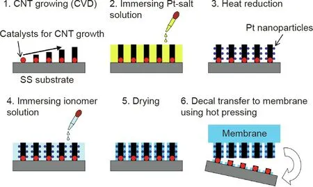
Fig. 5. Preparation procedure of CNT array electrodes. CVD: chemical vapor deposition. Reproduced from Ref. [26] with permission of Elsevier B.V., ©2014.
To overcome the drawbacks of Pt nanoparticles as well as the limited catalyst loading challenge on CNT array structures, our group developed a highly scalable approach to combine CNT arrays with 1D Pt nanostructures[33].Rather than using transferred substrates, CNT arrays were directly grown on GDLs using the PECVD technique. The CNT surface was then functionalized using active screen plasma nitriding (ASPN) to increase activity. Pt nanorods were grown on the N-CNT arrays using a facile aqueous formic acid reducing method at room temperature (Fig. 7) [33]. Thus, a high catalyst loading can be used without causing severe aggregation.Compared with the Pt/C nanoparticle electrode,our electrode with a half Pt loading showed an enhanced power density and better durability as cathodes in the single PEMFC test. Working as the cathode in the MEA, the Pt/N-CNT electrode showed a power density of 0.54 W·cm-2at 0.6 V with a catalyst loading of 0.19 mgPt·cm-2,compared with 0.44 W·cm-2for the Pt/C electrode at a catalyst loading of 0.41 mgPt·cm-2(Tanaka Kikinzoku Kogyo K.K. (TKK) Pt/C, 45.9%).

Fig. 6. Comparison of the power density change with various catalyst loadings for Pt/CNT and Pt/C cathodes in a single-cell test. MEA test conditions: Nafion 212 membrane; MEA active area of 2 cm × 2 cm; anode: 0.4 mgPt·cm-2 (JM Pt/C, 40%);cell temperature of 80 °C;H2/O2 with a backpressure of 0.2 MPa. Data are deduced from Ref. [28].
Although their performance is better than carbon nanoparticles,CNTs still suffer from poor tolerance to electrochemical corrosion at a high potential during start-up and long-term operation in PEMFCs. Therefore, metal oxides such as 1D TiO2nanostructures have been explored as the catalyst support for PEMFC applications.Unlike carbon materials, TiO2possesses a high tolerance to oxidation corrosion and has good interaction with metal catalysts.TiO2NTAs have been prepared by electrochemical anodic oxidation followed by wet chemical reduction or PVD to decorate catalyst nanoparticles [34], in a process that is very similar to catalyst decoration onto CNT arrays. When using TiO2as the catalyst support,the main challenge is its relatively poor electronic conductivity. As a result, the resistance of the TiO2NTA electrode can be ten times higher than that of a Pt/C nanoparticle electrode. Therefore,hydrogen treatment was conducted on TiO2nanostructures,which significantly enhanced the electrical conductivity close to the Pt/C catalyst in order to achieve an improved power performance [35].Further improvement was obtained by using carbon-coated aligned TiO2nanorods and nanotubes, which were also studied as catalyst supports for PEMFC applications[36,37].When the electrode made from Pt-sputtered carbon-coated aligned TiO2nanorod arrays was used as the cathode with a Pt loading of 28.7 μgPt·cm-2,the maximum power density was recorded at 0.343 W·cm-2,compared with 0.983 W·cm-2for a commercial Pt/C gas diffusion electrode(GDE)with a Pt loading of 0.4 mgPt·cm-2(testing conditions:Nafion 212 membrane;cell temperature of 65°C;fully humidified H2/O2with a backpressure of 0.05 MPa). No result has been reported for a high catalyst loading, but based on the knowledge from the CNT array support,a similar challenge is expected.Nevertheless, better durability was demonstrated using the accelerated degradation test (ADT) analysis (1500 potential cycles between-0.241 and 0.959 V(vs saturated calomel electrode(SCE))at a scan rate of 50 mV·s-1, anode H2, cathode N2). After the ADT, the ECSA retaining ratio of the Pt on the carbon-coated TiO2electrode was 89.4%, which was better than that of the Pt/C GDE (65.6%) [37].
4. Electrodes from 1D catalyst arrays
4.1. Excellent activities of single-crystal Pt nanowires
The stability of catalysts is a key factor in determining fuel cell durability. Although Pt-based nanoparticles are the most commonly used catalysts,their stability is still poor during PEMFC operation and cannot meet the requirements for practical applications(Fig.1(a)).Pt-based nanoparticles can degrade through a few mechanisms,including dissolution,aggregation,and Oswald ripening; in addition, they can detach from the carbon supports, which eventually results in low catalytic activities. These degradation processes were recently summarized in a review paper by Meier[38].During the past three decades,advances in material synthesis and nanotechnology have led to remarkable progress in PEMFC development, particularly in the understanding of fuel cell catalytic reactions and mechanisms on catalysts. Many new catalyst nanostructures have been reported to overcome the challenges facing Pt/C nanoparticles. Stephens et al. [4] and Escudero-Escribano et al.[8]compared various recent fuel cell catalysts,based on their mass activities toward ORR as measured by the half-cell electrochemical measurement technique in liquid electrolytes (Fig. 8)[8]. Among these, ultrafine jagged Pt nanowires with a diameter of 2.2 nm, prepared by fully leaching Ni from PtNi nanowires to form a rough surface, exhibited the highest catalytic activity thus far, of 13.6 A·at 0.9 V, which is 52 times higher than that of Pt/C nanoparticle catalysts (0.26 A·mgP-t1, 10 wt% Pt on carbon)[14].In addition to its large ECSA of 118 m2·gP-t1,the jagged Pt nanowire is considered to be the most promising catalyst for fuel cell applications and is attracting a great deal of attention from fuel cell researchers and manufacturers.
In comparison with their zero-dimensional (0D) counterparts,1D metal nanostructures—particularly 1D single-crystal metal nanostructures—exhibit several advantages, such as a high specific surface activity due to the large degree of exposure of highly active crystal facets, enhanced electron transport resulting from the path-directing effect within the catalyst layer,and high stability to alleviate the dissolution, Oswald ripening,and aggregation by the asymmetric structure. A comparison of nanoparticles with 1D nanostructures for fuel cell applications has been summarized in a few review papers, including one from our group [16,39].
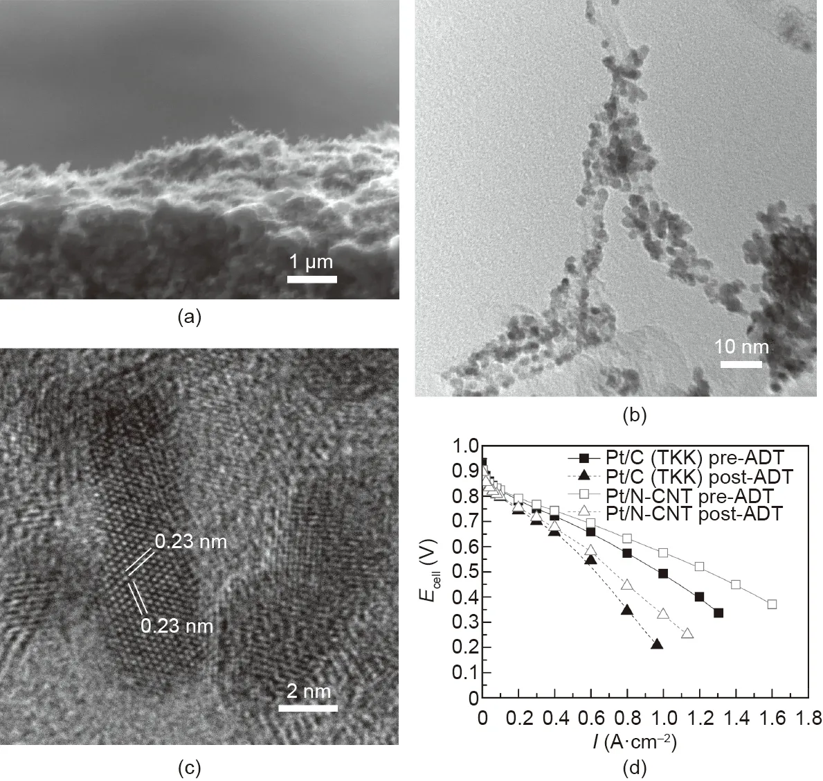
Fig. 7. (a) Cross-section SEM image of the GDL with deposited N-CNT arrays; (b) TEM images of N-CNTs decorated with Pt nanorods; (c) HRTEM image showing the interplanar lattice spacing of single-crystal Pt nanorods growing along the <111>crystal direction;(d)polarization curves of the Pt/C nanoparticle and Pt/N-CNT array electrodes before and after the accelerated degradation test(ADT).Test conditions:Nafion 212 membrane;MEA active area of 16 cm2;anode JM Pt/C gas diffusion electrodes(GDEs);cell temperature of 80°C,fully humidified H2/air with stoichiometric ratios of 1.3/1.5 and a backpressure of 0.05 MPa;ADT:3000 potential sweeping cycles between 0.6 and 1.2 V at a scan rate of 100 mV·s-1 with N2 at the cathode. Reproduced from Ref. [33] with permission of Elsevier B.V., ©2020.
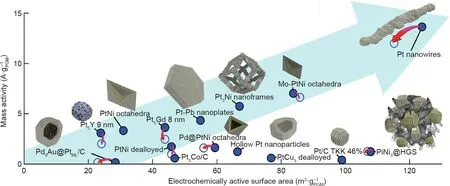
Fig.8. Mass activity comparison of various recent fuel cell catalysts(based on the reported value recorded using the half-cell measurement in liquid electrolytes).The filled and hollow blue circles show both activity and ECSA before and after the stability test. HGS: hollow graphitic sphere. Reproduced from Ref. [8] with permission of Elsevier B.V., ©2018.
However,fully transforming the superior catalytic performance of the latest generation of fuel cell catalysts to PEMFC devices remains a major challenge. There are two significant difficulties in applying high-performance 1D nanostructure catalysts to practical fuel cell applications. ①The first difficulty is scaling up the synthesis process to fulfil the large amount requirement in fuel cell applications. For example, PtNi nanoframes and jagged Pt nanowires have both been synthesized using an organic solvent oleylamine (OAm) process. The synthesis yield of this reaction is not very high, and product separation from the reaction system is sophisticated. For the laboratory-scale preparation and half-cell electrochemical measurement, a microgram-level amount is acceptable. However, for real application in fuel cells, a gramscale amount of catalyst is necessary,which presents the challenge of controlling the complex synthesis process to obtain high-quality materials [40]. ②The second difficulty is that, as 1D catalysts,nanostructures have different anisotropic morphologies with a larger aspect ratio than spherical Pt/C nanoparticles.Thus,electrodes fabricated using the conventional method optimized for Pt/C nanoparticles (i.e., coating with catalyst ink) cannot transform the outstanding catalytic properties of 1D catalysts to highperformance electrodes. In a half-cell measurement in a liquid electrolyte,a thin-film electrode is used with the rotating disk electrode(RDE)method.It is in a clean environment with ignored mass transfer influence. However, the situation in operating fuel cells is severe and complex; mass transfer issues including moving the reactant gases to the reaction sites and transferring the generated water outside also become key factors in determining fuel cell performance at large current density operation [41,42]. Thus, new electrode structure platforms such as 3D nanostructures from NWAs are required to bridge the gap between the exciting highly active 1D catalysts and high power performance fuel cell devices.
4.2. Electrodes from single-crystal Pt NWAs
Although the polyol process has been used to synthesize singlecrystal Pt nanowires, surfactants such as polyvinylpyrrolidone(PVP) are usually required to induce Pt growth. Another method using organic solvents,the OAm process,has also attracted a great deal of attention.Although the reaction does not require extra surfactant or ligand,it is still not an easy job to fully remove the OAm molecules adsorbed on the surface in order to achieve clean nanowires.The research conducted by St-Pierre et al.[43]indicates that many organic contaminants have adverse effects on fuel cell performance even at trace levels; these effects are even more prominent for low-Pt-catalyst-loading electrodes in practical operation, due to a concurrent increase in both the kinetic and mass transfer resistances[44]. In addition to the complex process,a high reaction temperature is necessary for these reactions in organic solvents. In comparison, the formic acid reduction approach is facile and can be conducted in an aqueous solution at nearly room temperature to grow nanowires. The intermediate species, formate anions produced from the dehydration of formic acid,can also be easily removed in rinsing steps after the nanowire growth, leaving a clean nanowire surface [45]. Therefore, the formic acid reduction method is considered as a green chemical process for material synthesis [46-48]. A detailed discussion and comparison of various methods for Pt-based nanowire preparation can be found in Refs. [49,50].
4.2.1. GDEs from single-crystal Pt NWAs
GDEs from single-crystal Pt NWAs were first reported by our group in 2010 [51]. With the GDL as a direct substrate, singlecrystal Pt NWAs were grown in situ onto the surface. The growing process was achieved using the formic acid reduction method at room temperature with a controlled slow reduction kinetic rate.In the formic acid reduction process, metal salts are reduced by the formate anion species produced from the dehydration of formic acid.For the Pt face-centered cubic(fcc)structure,this dehydration process is favored on the Pt surface, except for the Pt{111} crystal facet[52].Thus,by controlling the balance of undissociated formic acid and formate anion species—for example,by maintaining a low temperature—the growth of Pt along the <111>direction is automatically assisted to form 1D nanostructures. On the GDL surface,a 3D nanostructure was finally formed with a catalyst layer consisting of a monolayer array of single-crystal Pt nanowires with a diameter of about 4 nm and a length of 100-150 nm [51]. The Pt nanowires showed very good contact with the substrate and could be well retained under a strong sonication treatment. This GDL with Pt NWAs can be directly used as a GDE in PEMFCs. In comparison with the dispersed Pt/C process for the fabrication of electrodes,this direct Pt NWA GDE process is completed in a single step without free nanoparticles being produced at any point during the whole procedure (Pt nanoparticles are cytotoxic and can have negative impacts on human health [53]). This process also omits the steps of supporting Pt on carbon, catalyst ink making, and the coating process, thereby making the electrode fabrication process much simpler and more easily scaled up.
Unlike the NSTF catalyst, no regular vertically aligned pores formed between the catalyst nanowires because of the small diameter of the nanowires in the Pt NWA catalyst layer.The 3D structure within the catalyst layer is highly open;as a result,it is very easy to repel the water that is produced and prevent it from accumulating to form continuous water channels. Therefore, the degradation induced by local water flooding in the NSTF catalyst is successfully mitigated here. However, lacking of water channels for proton transfer also means that proton-conducting ionomer is still required to build a proton transfer network in the catalyst layer[54]. Comparison with a conventional Pt/C nanoparticle electrode demonstrated that a relatively higher ionomer loading was indeed required for the Pt nanowire electrode in order to achieve the best power performance, due to the enhanced open structure in the Pt NWA catalyst layer[54,55].The use of ionomer in the catalyst layer increased the decline possibility of the electrode performance during long-term fuel cell operation due to the decay of the ionomer and its contact with the nanowire surface. This poor contact between the ionomer and the Pt nanowires was confirmed with electrodes composed of single-crystal Pt nanowires grown on carbon nanospheres(PtNW/C).Li et al.[56]built 1.5 kW PEMFC stacks using PtNW/C and commercial Pt/C nanoparticles as the cathode catalysts, respectively. To evaluate catalyst stability in a real-life context, they conducted a durability test including 420 h of dynamic drive cycles. The PEMFC stack with the PtNW/C catalysts showed only a slightly lower power density decline rate of 14.4%compared with 17.9% for the stack with the Pt/C nanoparticles.Considering the confirmed outstanding stability of single-crystal Pt nanowires, transmission electron microscope (TEM) imaging and particle size histogram analyses were conducted on the cathode catalysts before and after the durability test; the results are shown in Fig.9[56].Minimal changes were observed in the PtNWs compared with the severe growth and aggregation of the Pt nanoparticles after the durability test. The very slight degradation of the PtNWs further demonstrates their excellent stability, and indicates that the power performance decline of the Pt nanowirebased electrode can mainly be ascribed to deterioration of the electrode structure—that is, to decay of the ionomer and to declined contact between the ionomer and the PtNW catalysts. Therefore,in order to address the durability challenges of fuel cell electrodes,particularly the issues with the new nanostructured catalysts, a fundamental understanding of the adhesion of the ionomer with the catalyst surface is necessary for future research.
For an electrode with a monolayer array of Pt nanowires within the catalyst layer, an optimal Pt nanowire distribution density determined by the Pt loading is key to achieve high power performance PEMFCs.Increased catalyst loading can lead to better power performance, but a too-high Pt loading tends to form Pt nanowire agglomerates and reduce the catalyst utilization ratio in the electrode(Fig.10)[57].Therefore,in order to attain a high catalyst utilization ratio at a high catalyst loading, an electrode with uniformly distributed Pt nanowires and little(or even no)agglomeration is strongly preferred.

Fig. 9. (a-d) TEM images and (e-h) histogram particle size distribution diagrams of the PtNW/C nanoparticle catalyst (a, e) before and (b, f) after a durability test and Pt/C nanoparticle catalysts(c,g)before and(d,h)after a durability test in the cathodes of 1.5 kW PEMFC stacks,respectively.Polarization and power density curves for(i)PtNW/C and(j)commercial Pt/C before and after the durability test.Test conditions: MEA active area of 250 cm2;Nafion 212 membrane;cathode catalyst loading of 0.4 mgPt·cm-2;anode:Pt/C HiSpec 400 0.2 mgPt·cm-2;fully humidified H2/air.RH:relative humidity.P(A/C):backpressure at the anode and cathode.Stoich(A/C):stoichiometry ratio at the anode and cathode. Reproduced from Ref. [56] with permission of Elsevier B.V., ©2015.
When GDLs are fabricated,they are usually treated with polytetrafluoroethylene(PTFE)polymer to achieve super-hydrophobicity.During PEMFC operation, this hydrophobicity can facilitate the repelling of the generated water to prevent water flooding and can enable effective diffusion of the reactant gas to the catalyst surface. However, this super hydrophobic surface is highly nonwettable to aqueous reaction solution during the formic acid reducing process. The inert GDL surface provides very limited nucleation sites; thus, many nanowires tend to grow from the few crystal nuclei formed on the GDL surface, which eventually results in very large nanowire agglomerates (Figs. 10(e) and (g)).To overcome this drawback,our group employed a few techniques to improve nanowire distribution within the Pt NWA catalyst layer.
The influence of GDL structures, including the top microporous layer (MPL) and the carbon fiber substrate, was investigated in order to understand their influences on Pt nanowire growth [58].The results demonstrated that while the substrate had very little effect on nanowire growth,the nucleation sites on the top MPL surface played a major role in controlling the growth of the Pt NWAs to balance mass transport within the catalyst layer. A thick MPL under a high carbon loading was found to increase mass transport losses;however,a too-low carbon amount was not effective in covering the entire surface, resulting in the growth of Pt nanowires into the carbon fiber substrate which contributed little to the electrode catalytic performance. The optimal carbon loading in the MPL was finally determined to be 4 mg·cm-2.Two types of carbon black (CB) were also studied for fabricating the MPL: CB with a good number of surface defects and acetylene black (AB) with a more inert particle surface. It was found that a mixture of equal amounts of CB and AB provided the best porosity and nucleation site number on the surface for the growth of Pt NWAs.A dominating CB content provided a more hydrophilic MPL, inducing the reaction solution to penetrate into the deep pores below the surface, and forming nanowires there that could not be reached by the ionomer and that contributed very little to the fuel cell reaction.In contrast,with a very high AB ratio,there were very limited nucleation cites on the inert MPL surface;thus,large agglomerates formed with a highly nonuniform distribution of nanowires. Similar to when a super hydrophobic binder was used in the MPL, the PTFE loading needed to be kept very low to maximize the nucleation sites on the surface,while remaining effective enough to prevent water flooding during PEMFC operation.
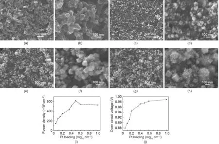
Fig. 10. (a, b) SEM images of the GDL surface. (c-h) SEM images of Pt nanowire GDEs with various catalyst loadings: (c, d) 0.1 mg·cm-2; (e, f) 0.5 mg·cm-2; and(g,h)1.0 mg·cm-2.(i)The maximum power density and(j)open circuit voltage under various catalyst loadings. Test conditions: Nafion 212 membrane;MEA active area of 16 cm2;cell temperature of 70°C;H2/air with stoichiometric ratios of 1.5/2.0 at 50%RH and 0.15 MPa backpressure.Reproduced from Ref.[57]with permission of Hydrogen Energy Publications, LLC, ©2012.
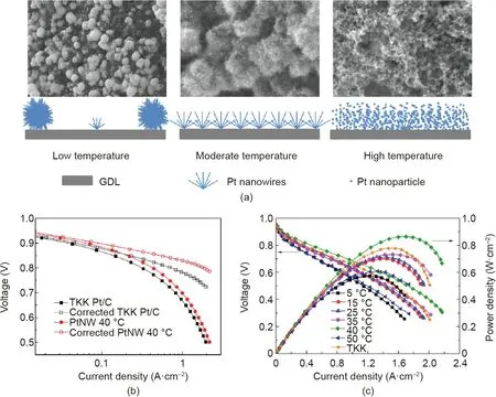
Fig. 11. (a) SEM images and a schematic illustration of Pt nanostructures deposited on the GDL surface using the formic acid reduction method at low, moderate, and high temperatures.(b)Original and corrected polarization curves of MEAs with the Pt/C and PtNW GDEs as cathodes for mass activity determination,recorded at 80°C with fully humidified H2/O2 at 0.15 MPaabs and stoichiometric ratios of 2/9.5(Nafion 212 membrane,MEA active area of 16 cm2).(c)Polarization curves of MEAs with cathodes made of Pt/C(TKK)and PtNW GDEs grown at different temperatures,recorded at 70°C with fully humidified H2/air and stoichiometric ratios of 1.3/2.4 at a backpressure of 0.2 MPa.Reproduced from Ref. [59] with permission from Elsevier B.V., ©2015.
The reaction temperature for the in situ growing process was also studied in order to tune the distribution and structure of the Pt NWAs on the GDL surface (Fig. 11(a)) [59]. At a low reaction temperature(i.e.,15°C),the contact of water with the GDL surface was poor and very few defect sites could be used for crystal nucleation; thus, Pt nanowires only grew from a limited number of nuclei, and eventually formed huge agglomerates that resulted in a low catalyst utilization ratio and poor electrode power performance. A higher reaction temperature improved the contact between the reaction solution and the GDL surface, facilitating the formation of Pt NWAs with better distribution. However, at a high temperature(i.e.,50°C),the energy provided was greater than the barrier required for homogeneous nucleation in the reaction solution; thus, small Pt nanoparticles formed rather than nanowires.These nanoparticles eventually piled up on the GDL surface,which dramatically reduced the catalyst utilization ratio. The GDE fabricated at 40 °C showed the highest peak power density in the H2/air PEMFC test. Arrays with uniformly distributed singlecrystal Pt nanowires with a length of 10-20 nm were achieved on the GDL surface. The ECSA of the Pt NWA electrode was still much lower than that of the Pt/C (TKK, 45.9%) nanoparticle electrode (34.37 and 56.87 m2·g-1, respectively; CV recorded with H2/N2at the anode and cathode, respectively, at 70 °C). However,the high intrinsic activity of the single-crystal Pt nanowires resulted in specific activity that was more than three times larger,which led to a doubled mass activity (0.225 to 0.118 A·mgP-t1at 0.9 V;Fig.11(b))in the MEA test;together with the enhanced mass transport performance that resulted from the NWAs,a power density of 0.82 W·cm-2was recorded at 0.6 V for the MEA with the Pt NWA GDE, in comparison with 0.74 W·cm-2for the Pt/C nanoparticle electrode(Fig.11(c)).A durability evaluation using the potential cycling(between 0.6 and 1.2 V for 2000 cycles at a scan rate of 50 mV·s-1) also demonstrated a slower degradation rate of the Pt NWA GDE,which exhibited an ECSA loss of 48%after the ADT,compared with 67% for the Pt/C nanoparticle electrode.
Although controlling the reaction temperature at 40 °C effectively improved the Pt nanowire distribution, the small temperature window created major difficulties for a practical electrode fabrication process. Other surface functionalization technologies were then explored to control the Pt nanowire growth at room temperature. Palladium (Pd) nanoparticles have been used as nanoseeds to control the growth of PtPd bimetallic nanodendrites on graphene nanosheets, since Pd can easily be reduced due to its higher standard reduction potential and is more wettable (cf. Pt)[60-62]. Furthermore, forming a hybrid with Pd can potentially increase the catalytic activities and stability of Pt. Therefore, Pd nanoparticle seeds were deposited onto the GDL surface to improve the distribution of Pt nanowires [63]. The results demonstrated an optimal Pd amount of 5 at%, which led to more uniformly distributed PtPd nanostructures on the GDL surface,although the length of the nanowires was slightly reduced to 5-20 nm to form nanodendrites(Fig.12(a))[63].The better distribution somewhat improved the power density from 0.64 to 0.73 W·cm-2(at 0.6 V), and the ECSA measured in the cathode increased from 14.70 to 22.40 m2·g-1, although it remained lower than that obtained at 40°C(Figs.12(b)and(c)).However,the durability test demonstrated a larger decline rate of the power density for the PtPd nanodendrite electrode,showing a degradation ratio of 20.1%compared with 12.7%for the Pt NWA electrode.Considering the smaller ECSA drop and the enhanced stability usually reported for PtPd hybrids in comparison with Pt, the larger drop can be mainly ascribed to degradation of the PtPd catalyst layer,although detailed mechanisms still need further research for a clear confirmation.
Introducing Pd nanoparticle seeds improved the distribution of the Pt NWAs, but also caused a rapid decline of the electrode performance in the fuel cell test. Plasma surface treatment was then introduced as an alternative solution. Plasma surface treatment is known as an efficient technology to activate solid surfaces.Considering the low processing temperature required for the GDLs,ASPN was deployed to activate the GDL surface for the in situ growth of uniform Pt NWAs [64,65]. Unlike oxidation activation, which uses strong acids that can destroy the surface of all pores throughout the whole GDL, ASPN only amends the very top surface, typically superficial 5-50 nm, and the bulk features of the GDL can be well retained.The ASPN activation was conducted at 120°C under a gas mixture of N2/H2. This treatment successfully introduced several types of functional groups, including C-N, C=N, and O-H, onto the GDL surface, which increased the surface activities and facilitated the formation of uniformly distributed Pt nuclei across the entire surface area. These nuclei enabled the growth of Pt NWAs without forming large agglomerates,resulting in improved catalyst utilization within the electrode (Figs. 13(a) and (b)) [64]. Furthermore, the ASPN treatment introduced nitrogen (N) dopant and other defects to the GDL surface,confining Pt atoms in formic acid reduction facilitating the formation of tiny nuclei, which induced Pt crystal growth to achieve ultrafine Pt nanowires with an average diameter of 3.0 nm (Figs. 13(c) and (d)). The Pt nanowires with a small diameter provided a large specific surface area, enabling a similar ECSA to that of Pt/C nanoparticles in electrodes (25.4 to 25.8 m2·g-1, Fig. 13(e)). The enhanced catalyst utilization ratio and ECSA improved the electrode power performance. The test as cathodes toward the ORR (in direct methanol fuel cells, DMFCs)demonstrated that with a half Pt loading, the MEA with the Pt NWA cathode (2 mgPt·cm-2) showed a higher power density than the Pt/C nanoparticle electrode with 4 mgPt·cm-2(64 and 47 mW·cm-2at 0.4 V, respectively; Fig. 13(f)).
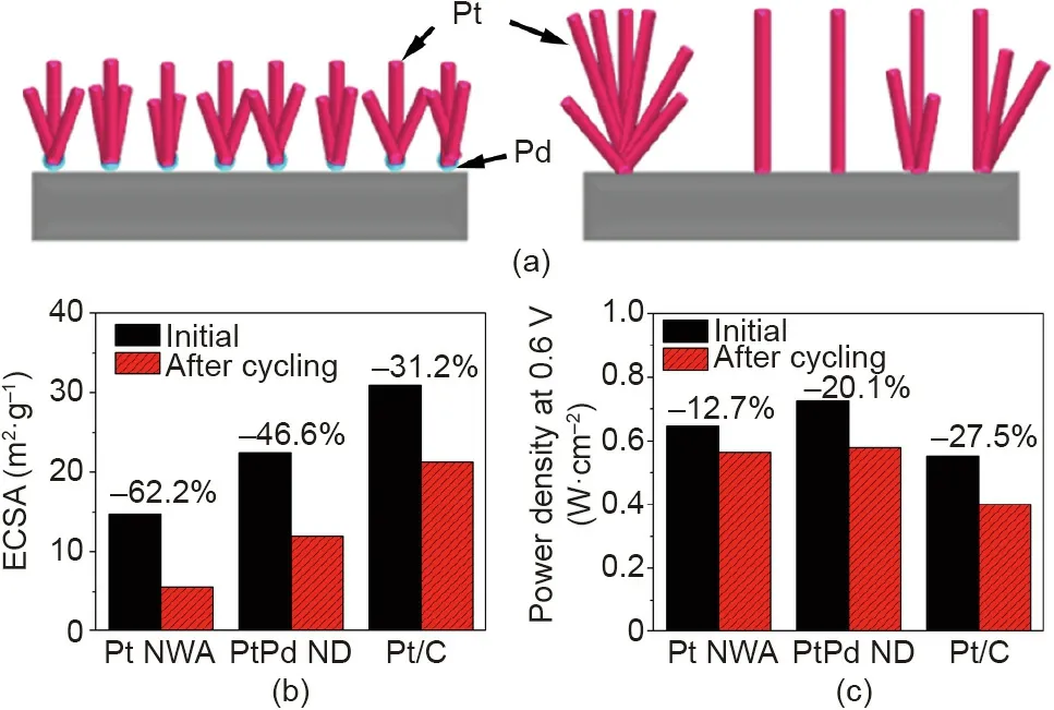
Fig. 12. (a) Schematic of the introduction of Pd nanoparticle seeds to improve the distribution of Pt nanowires. Comparison of (b) ECSAs and (c) power densities for MEAs with the PtPd nanodendrite (ND) (5 at% Pd), Pt NWA, and Pt/C nanoparticle GDEs before and after the durability test using potential cycling. Test conditions:Nafion 212 membrane; MEA active area of 16 cm2; cell temperature of 70 °C;cathode CV recorded with H2/N2; polarization curves recorded with fully humidified H2/air with stoichiometric ratios of 1.3/2.4 at a backpressure of 0.2 MPa. Durability test was conducted using the potential cycling between 0.6 and 1.2 V for 3000 cycles at a scan rate of 50 mV·s-1. Reproduced from Ref. [63]with permission of Elsevier B.V., ©2016.
4.2.2. Catalyst-coated membrane from single-crystal Pt NWAs
Compared with the GDE method,the catalyst-coated membrane(CCM)or decal approaches show more potential for the fabrication of MEAs with better contact between the PEM and catalyst layer for enhanced power performance [2]. For GDEs from singlecrystal Pt NWAs, the uneven MPL surface of the GDL (Figs. 7(a),10(a), and 10(b)) prevents the top ends of the NWAs from being in a horizontal plane; thus, when they are hot pressed onto the PEM,only some of them will have good contact with the PEM,even after a thin layer of proton-conducting ionomer is coated onto the GDE surface.If the NWAs can be grown on a flat PEM or decal substrate surface, however, this situation will be improved.
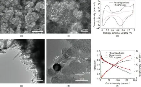
Fig.13. Pt nanowires grown in situ on active screen plasma nitrided GDLs.(a,b)SEM images of Pt NWAs on the GDL surface.(c)TEM image of Pt nanowires scraped from the Pt NWA GDE. (d) An HRTEM image of the area specified by a white square in (c), showing the single-crystal Pt nanowires growing along the <111>crystal direction.(e) Cathode CV and (f) polarization curves of the MEAs with cathodes made from the Pt NWA electrode (2 mgPt·cm-2), Pt/C electrode (JM DMFC cathode, 4 mgPt·cm-2), and plasma-treated GDL tested in a 5 cm2 DMFC.Test conditions:Nafion 117 membrane;cell temperature of 75°C;commercial JM anode(4 mgPtRu·cm-2).CV was recorded with the cathode fed with ultrapure water at 1 mL·min-1 and the anode fed with non-humidified hydrogen at a flow rate of 100 standard cubic centimeters per minute (sccm).Polarization curves were recorded with the anode fed with 1 mol·L-1 methanol at a flow rate of 1 mL·min-1 and the cathode fed with non-humidified air with a flow rate of 100 sccm without backpressure. DHE: dynamic hydrogen electrode. Reproduced from Ref. [64] with permission of Springer Nature Limited, ©2014.
Nafion membrane,a commonly used membrane in PEMFCs,is a combination of a stable PTFE backbone with acidic sulfonic groups.It is very difficult to form uniformly distributed nucleation sites on the PEM surface in order to grow NWAs due to the inert backbone.To mitigate this obstacle, our collaborator Sui et al. [66] and Yao et al. [67] introduced a thin carbon powder matrix onto the PEM surface as a functional layer to grow Pt nanowires. This carbon matrix surface plays the same role as the MPL in GDLs for nanowire growth, but is much flatter with an even PEM surface and a thin matrix layer [66,67]. The same formic acid reduction method was then deployed to grow Pt NWAs onto the matrix. The PEM with the matrix and Pt nanowires was then directly used as the half-MEA for the PEMFC test. The carbon matrix thickness, protonconducting ionomer coated on the catalyst layer, and Pt nanowire loading were optimized based on the MEA power performance[68,69]. The results demonstrated the importance of controlling the structure to maximize the TPB within the catalyst layer. This was done in a number of ways, including the following:
(1)When a very thin carbon matrix layer was used,and the distribution of Pt nanowires through the catalyst layer was consistent.However,all of the Pt nanowires were restrained within a very thin layer, and the limited nucleation sites resulted in many large agglomerates, which partially blocked local pores. On the other hand,if the matrix layer was too thick,the reaction solution penetrated into the matrix and a thick catalyst layer was obtained with Pt nanowires showing a gradient distribution from the surface to a deep level; this resulted in a low catalyst utilization ratio.
(2)A very high Pt loading caused heavy agglomeration of the Pt nanowires, resulting in a low ECSA and large mass transfer losses.An optimized Pt catalyst amount of 0.30 mgPt·cm-2in the catalyst layer and a carbon powder loading of 0.10 mg C (mgC) per square centimeter in the matrix were demonstrated to have the highest power density in the PEMFC test.
(3) The optimal ionomer content mixed into the carbon matrix layer was shown to be 10 wt% (to carbon in the matrix), and the optimal ionomer content coated onto the surface of the Pt NWA catalyst layer was shown to be 8 wt%(to the Pt loading).The Nafion ionomer content in the carbon matrix could be used to control the number of nucleation sites on the surface,thus tuning the agglomeration and distribution of the Pt nanowires. Although coating the ionomer onto the surface of the Pt NWAs improved the proton conductivity, excess ionomer partially blocked the pores, which increased the mass transfer resistance. Pt/C nanoparticle catalysts were also introduced to replace carbon powder in the matrix as crystal seeds for nanowire growth[70].A reduced optimal Pt loading of 0.20 mgPt·cm-2was obtained in the Pt NWA catalyst layer.However,the Pt/C matrix resulted in the formation of Pt nanowires with a less ordered crystalline structure, shorter length,and lower catalyst activity than those that formed with the carbon matrix.
To further improve the contact between the Pt nanowires and the PEM,the decal approach was then introduced to grow Pt NWAs[71-73]. The carbon matrix was coated onto a transfer substrate(e.g., PTFE film), which was followed by the same formic acid reduction method to grow NWAs. The structure was then transferred to PEM in order to fabricate MEAs. It was found that the introduction of a small amount of Pt/C nanoparticles into the carbon matrix had a positive effect,facilitating the growth of uniform Pt NWAs. An optimal Pt/C loading was found to be 5 μgPt·cm-2with a carbon amount of 20 μgC·cm-2in the carbon matrix. The cathode with a total Pt loading of 0.205 mgPt·cm-2(5 μgPt·cm-2with the Pt/C nanoparticle matrix and 0.2 mgPt·cm-2with the Pt NWAs) showed a peak power density similar to that of the Pt/C nanoparticle electrode, with a catalyst loading of 0.40 mgPt·cm-2in the H2/air PEMFC test, but a more than double specific mass power density of 89.56 A·gPt-1(cf. 42.58 A·gP-t1) at 0.9 V (Fig. 14)[73]. These findings showed the strong potential of the decal approach for the fabrication of Pt NWA electrodes.
4.3. Electrodes from Pt-based NTAs
As 1D nanostructures, Pt-based nanotubes have advantages similar to those of nanowires. They also suffer less than Pt nanoparticles from dissolution,aggregation,and Ostwald ripening.Furthermore, nanotubes can provide a high surface area and are more easily prepared in an alloy form for enhanced catalytic activities. For these advantages, Pt and Pt alloy NTAs have also been explored for PEMFC applications.
Galbiati et al. [74,75] and Marconot et al. [76] prepared Ptbased NTAs using a sacrificial template of porous anodized aluminum oxide (AAO). Pt was deposited onto the inside wall of the AAO pores using atomic layer deposition (ALD) [74] or electron beam evaporation (EBE) [75] techniques. The Pt-coated AAO template was then decal transferred to the PEM surface by hot pressing, which was followed by the removal of the AAO template using NaOH. With this approach, depending on the pore size of the AAO template, arrays of Pt nanotubes were obtained with an external diameter of 150-180 nm and a wall thickness of around 20 nm. The large diameter resulted in a small ECSA, although a higher surface utilization(160%cf.Pt/C)was demonstrated.To further increase the specific surface and mass activities, these researchers prepared copper (Cu) nanowires using the AAO template, which was followed by a galvanic displacement reaction with chloroplatinic salt to develop PtCu NTAs [76]. The prepared nanotubes had an average diameter of 30 nm with a highly porous wall made up of 3 nm PtCu alloy nanoparticles. A catalyst layer 2 μm thick was finally obtained that consisted of an NTA with a distance between nanotubes of 60 nm (ca. 3.2 × 10¹⁰nanotubes·cm-2).With the PtCu nanotubes,the obtained structure demonstrated a specific activity ten times higher (2.2 mA per square centimeter of Pt (cmP2t) than that of the Pt/C catalyst(200 μA·cmPt-2)at 0.9 V toward the ORR at the cathode(MEA tested with fully humidified H2/O2at 40 °C and 1.5 bar (1 bar = 105Pa),catalyst loading 20 μgPt·cm-2), but testing in H2/air showed no improvement.
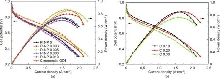
Fig.14. Polarization and power density curves of MEAs with cathodes made from a Pt/C nanoparticle GDE or Pt NWA electrodes fabricated with a carbon matrix containing(a)various Pt/C contents from 0 to 0.010 mgPt·cm-2 and(b)a carbon loading of 0.10,0.20,or 0.30 mgC·cm-2.The Pt nanowire loadings for all samples were 0.20 mgPt·cm-2.The carbon and Pt/C loading in the matrix were (a) 20 μgC·cm-2 and (b) 5 μgPt·cm-2, respectively. Test conditions: Nafion 212 membrane; MEA active area of 10 cm2; cell temperature of 70°C;H2/air with stoichiometric ratios of 1.5/2.0 and a backpressure of 0.1 MPa humidified at 65°C.Reproduced from Ref.[73]with permission of Hydrogen Energy Publications LLC, ©2018.
Rather than using the sacrificial AAO template, open-walled PtCo bimetallic NTAs were fabricated by means of a combination of hydrothermal synthesis and PVD technique [77]. Templated Co-OH-CO3NWAs were first grown on a substrate by a hydrothermal method; next, the magnetron sputtering technique was used to coat a Pt layer onto the nanowire surface. Thermal annealing was then used to alloy Pt and Co in order to enhance the catalytic activity, which was followed by acid washing after the decal process to finally remove the template and obtain the PtCo NTA electrode. This process is schematically shown in Fig. 15(a) [77]. The fabricated catalyst layer was about 300 nm thick and the obtained PtCo nanotubes had an average diameter and wall thickness of 100 and 17 nm,respectively.In a single-cell test,the MEA with the PtCo NTA cathode (annealed at 400 °C) at a catalyst loading of 0.0527 mgPt·cm-2showed a peak power density of 0.758 W·cm-2in comparison with 0.841 W·cm-2for a Pt/C cathode with 0.1 mgPt·cm-2(JM Pt/C,70%)(Fig.15(b)).Excellent durability was also observed for the PtCo NTA cathode. After the ADT (5000 cycles by sweeping potential between 0.6 and 1.0 V vs reversible hydrogen electrode (RHE) at a scan rate of 50 mV·s-1, 80 °C, H2/N2), the maximum power density dropped to 0.458 W·cm-2for the PtCo NTA cathode, which was much higher than 0.196 W·cm-2for the Pt/C electrode. However, the use of toxic NH4F in the preparation process of the Co-OH-CO3NWAs somewhat lowers the commercial potential of this process.
5. Challenges and opportunities
5.1. Limitation of current 1D nanostructure array electrode approaches
5.1.1. Small ECSA
A major challenge with the single-crystal Pt-based NWA electrodes is the low ECSA resulting from the large diameter of the catalyst nanowires. The largest ECSA we recorded was 34.37 m2·g-1with Pt NWAs grown in situ on GDLs at 40 °C,which is still only half of that of Pt/C nanoparticle catalysts.For this situation, the length of the nanowires was significantly shortened to less than 20 nm. To develop high power performance fuel cells, a large ECSA is necessary; thus, the diameter needs to be reduced,with the ultimate goal of using ultrafine jagged Pt NWAs. Jagged Pt nanowires with a diameter of 2.2 nm have been reported to have an ECSA of 118 m2·gPt-1, which is even higher than that of Pt/C nanoparticle catalysts, making these nanowires as the catalysts with the highest mass activity(13.6 A·gPt-1)reported to date(Fig.8).
As the most promising catalyst material,the ultrafine jagged Pt nanowires are being worked on by many research groups and fuel cell manufacturers with the expectation of scaling up the process for the development of next-generation PEMFCs. A breakthrough is urgently required to fully transfer the superior activities of the jagged Pt nanowires to working electrodes in order to realize the dream of PEMFCs operated at a high power density with longterm durability [4]. The concept of 3D electrodes from NWAs fits the jagged Pt nanowires perfectly, but the challenges with current preparation approaches limit further progress. Pt-transitional metal alloy NWAs need to be prepared first,before the transitional metal can be fully leached to achieve the jagged Pt nanowires.With the current OAm process, both the preparation and separation procedure are too complex and ineffective to fulfil the practical requirements for PEMFC applications. Furthermore, it is extremely difficult to really grow NWAs on the substrate with the OAm process, which is limited by the synthesis principles.
The simplicity and green preparation process make the formic acid reduction method a promising approach to fabricate Pt NWA electrodes. In addition to our progress in the modification of the substrate surface to improve Pt nanowire distribution, such as the ASPN activation,more techniques are still required to precisely control the nanowire distribution in order to form well-designed 3D structures that can accurately tune the catalyst exposure and mass transport behavior within the catalyst layer. This method shows some potential for the fabrication of ultrafine jagged Pt NWAs.However,a slow reduction rate is required to form Pt nanowires with this weak reductant at near room temperature,and the reducing potential of formic acid is not strong enough to simultaneously reduce transitional metal ions to achieve single-crystal Pt alloy nanowires.Our group tried the impregnation of a nickel (Ni)precursor onto the Pt NWA surface followed by hydrogen (H2)reduction to fabricate PtNi nanowires [78]; however, it was found that the Pt nanowires could not stand the high reduction temperature (ca. 400 °C) that was required for Ni alloying. The hydrothermal reduction process on the metal substrate(e.g.,SS or Al),combined with the decal transfer approach,shows some possibility for this application, but the feasibility still requires experimental confirmation, and the scale-up remains a major challenge.

Fig. 15. (a) Schematic process for fabricating CCMs based on PtCo NTAs. (b) Single-cell performance of CCMs based on a macroporous Pt thin layer (MPTL), and PtCo NTAs annealed at 300,400,and 500°C.Testing conditions:Nafion 212 membrane;MEA active area of 2.56 cm2;cell temperature of 80°C;H2/O2 with 80%RH and a backpressure of 0.2 MPa. Reproduced from Ref. [77] with permission of Elsevier Ltd., ©2017.
Formation of an NSTF catalyst layer is an important approach in the development of vertically aligned 1D nanostructure electrodes.In combination with the PVD method,this approach has been confirmed as a technique to fabricate MEAs based on a roll-to-roll process. A major challenge with this approach is the low ECSA that results from the large size of the whiskerette-shaped catalyst structures(ca.9 nm),which are required to cover the entire surface of the large polymer whisker in order to prevent them from corrosion during fuel cell operation. Another major issue with this approach is the severe water flooding that is caused by the channel space between the catalyst whiskers and their hydrophilic surface.Although 3M Company has introduced some techniques,such as a gradient anode GDL structure to improve water management, and leaching combined with annealing approach to improve the catalyst surface properties. However, these approaches also result in the loss of some advantages of this unique electrode structure.Thus, significant efforts are still required in order to finally transition this electrode approach into commercial applications.
5.1.2. Limited catalyst loading
Electrodes from Pt nanoparticle-decorated 1D support arrays,including arrays of polymers, CNTs, and TiO2nanotubes and nanorods, are hot topics in PEMFC research. Such electrodes can easily provide a large ECSA using the well-controlled process to generate small catalyst nanoparticles.However,in order to maintain good dispersion and prevent aggregation of the catalyst nanoparticles,a low catalyst loading must be used (Fig. 6). A very high specific mass power density can usually be achieved while meeting the mass activity target set by the US Department of Energy regarding PEMFC catalyst development. Nevertheless, for practical applications, a high power density operation is required,which is usually not possible using these approaches.For example,at a moderate Pt loading of 0.1 mgPt·cm-2,the electrodes from nanoparticle decorating support arrays have often recorded a lower power density than Pt/C electrodes.To overcome this drawback as well as the poor stability of extremely small catalyst nanoparticles, a replacement by 1D Pt nanostructure catalysts can be a possible solution.However,in this case, the advantage of the large ECSA from nanoparticles and the question of how it can be retained remain somewhat unclear, compared with the current understanding of the electrodes from self-standing 1D catalyst nanostructure arrays. Furthermore, breakthroughs are necessary to simplify the complex preparation process and to address the poor intrinsic conductivity of the polymer whiskers and metal oxide supports.
5.1.3. Mechanical stability
In MEA fabrication,a hot-press step is usually required for both GDE and decal techniques,which could challenge the ability of 1D nanostructure arrays to maintain their integrity.Scanning electron microscope (SEM) analysis of the NSTF catalyst [19], Pt nanowire[54,73],and PtCo nanotube[77]array electrodes has demonstrated that the entire structure could experience some deforming and the packing of catalyst nanostructures and the space between them could slightly change; however, no problems have been reported regarding the integrity of the total electrode structure. The electrodes from the self-standing catalyst nanotubes are still limited by the great thickness of the nanotube walls and by the complex process based on the template approach[79,80].The development of extremely thin nanotubes can potentially increase catalytic activities, although the mechanical strength will become weak and further strategies will then be required to address this subsequent problem.A direct observation of the structural change under pressure,such as by online SEM or atomic force microscope(AFM)analysis, could be conducted to obtain further understanding and to provide more knowledge for future design.
5.2. Electrode structure research
To further improve 3D structured electrodes, a fundamental understanding of the structure-property relationship is necessary,including an understanding of the voltage losses caused by charge and mass transfer resistance, and the ionomer distribution on the catalyst surface and within the catalyst layer;this will make it possible to predict trends in performance by controlling the electrode design. Recent progress in numerical simulation techniques[81,82]—particularly in the development of artificial intelligence(AI)-based optimization [83]—has shown good potential for achievements in this area.
5.2.1. Mass transfer behavior
It has frequently been concluded that the 3D ordered electrodes from 1D nanostructure arrays can provide improved mass transfer behavior based on the aligned catalyst structures and open space.However,the oxygen mass transport resistance in the PEMFC cathode is a very complex parameter, comprising bulk (molecular diffusion), Knudsen, and interfacial effect (i.e., oxygen permeating through the catalyst-ionomer-water interface) transport resistance [84]. Molecular diffusion resistance is pressure dependent,while both Knudsen and interfacial diffusion resistance are pressure independent.The 3D ordered electrode structure can facilitate oxygen transport to reduce the molecular and Knudsen resistances,but there is no clear understanding for its influence on the oxygen transport through the ionomer layer on the catalyst surface.However, no quantification has been applied to electrodes from 1D structure arrays,although some early studies have shown that this can possibly be done based on polarization curves at different air feed rates and stoichiometry ratios [85]. It is necessary to conduct a study on 3D ordered electrodes in particular,in order to guide the design from the most active catalyst(i.e.,ultrafine jagged Pt nanowires); this has not been achieved as yet.
5.2.2. Ionomer dispersion on 1D structures
The oxygen mass transport resistance for permeating through the ionomer layer on the catalyst surface can cause high voltage losses for a low catalyst loading/high current density operating cathode[86,87].This is strongly determined by the ionomer distribution on the catalyst surface,which also has a major influence on the building of an ionomer network for a proton-conducting path within the catalyst layer. Thus, the ionomer distribution on the catalyst surface determines both the mass and charge transport resistance within the electrode.
For 1D nanostructures, and even for nanowire catalyst arrays,the surface contact with the ionomer can be very different from that with conventional Pt/C nanoparticles,due to the changed morphology, catalyst surface, and electrode structure. This is particularly true for the preferred crystal face exposure with singlecrystal 1D catalyst nanostructures (e.g., {111} for single-crystal Pt nanowires and high index facets for jagged Pt nanowires), which determine the sulfonate site adsorption on the catalyst surface and thus affect the adhesion with the ionomer [13]. Furthermore,because of the thin catalyst layer developed with 1D nanostructure array electrodes, the volume water generation rate will also be much higher (20-30 times higher) than that of Pt/C nanoparticle electrodes during PEMFC operation. Therefore, the ionomer can exhibit very different behaviors,including distribution, expansion,shrinkage, and degradation. Recent work conducted by Ott et al.[88] demonstrated that the use of an N-modified carbon support for Pt/C resulted in an unprecedentedly uniform coverage of the ionomer on surface, leading to a record high power density of 1.39 W·cm-2from a pure Pt catalyst(tested in a 1.4 cm2MEA with GORE MX20.10 10 μm membrane at 80°C under H2/air at 100%RH and 0.23 MPaabs;cathode,~0.11 mgPt·cm-2;anode,TKK Pt/C 19.7%,0.15 mgPt·cm-2). This finding indicates the importance of understanding the ionomer distribution on the 1D catalyst surface and within the 1D catalyst arrays in the electrode, as well as understanding the potential of tuning the catalyst surface to improve the contact with the ionomer. Further knowledge of ionomer contact with various catalyst nanostructures, which can be obtained by probing the intermolecular and interfacial forces using various nanomechanical tools and methodologies [89] and by monitoring the behavior of ionomers during fuel cell operation, will provide an invaluable reference for guiding the design and development of electrodes from 1D catalyst arrays.
5.2.3. Ionic liquid modification
In addition to studies on novel catalyst nanostructures and electrode fabrication techniques, surface and structure modifications of catalysts and electrodes using protic ionic liquids(ILs)have been studied in recent years. The excellent oxygen solubility and diffusivity of ILs can help to maximize the contribution of active catalyst sites within the mesopores of catalyst nanostructures, which are too small to be penetrated by the large polymer clusters of the proton-conducting ionomer(e.g.,Nafion)[90].Thus,IL modification can increase the catalyst utilization ratio in electrodes.Furthermore,the hydrophobicity of ILs can protect the catalyst surface from direct contact with acidic water during fuel cell operation[41,91] and can help to limit the build-up of generated water on the exterior of the catalyst to improve oxygen mass transport performance [92]. Although the enhancement mechanisms of the IL modification for catalysts in PEMFCs are still under debate, some positive effects have been confirmed. In particular, the positive effects that ensue from surface protection and access to mesopores make IL modification an ideal approach to modify low-cost highly porous non-PGM catalysts (e.g., FeCN and CoCN deduced from metal-organic frameworks(MOFs))for PEMFC applications,which can potentially help in addressing the major challenge of poor stability due to corrosion in an acidic operation environment. However, the leaching of ILs under severe fuel cell operation conditions and evaporation over long-term use remain unclear,although a few papers have demonstrated the excellent durability of ILs for modifying Pt-based catalysts based on testing results in PEMFCs[91,92].Given that this research is still quite new and that there is a growing number of reported work in this area, more knowledge is expected to clarify these points and provide strategies to address the potential issues.
6. Conclusions
This paper reviewed recent advances in 3D catalyst electrode design based on 1D nanostructure arrays for PEMFC applications.Significant progress has been achieved,from the earliest NSTF catalyst layer to Pt nanoparticle-decorated carbon and TiO2nanotubes arrays, and to self-standing catalyst layers based on Pt NWAs and NTAs. The thin catalyst layer with the vertically aligned structure enables better mass transport performance in practical electrodes,resulting in an extremely high degree of active site exposure and catalyst utilization. Outstanding catalytic performance and durability were reported, and significant potential was demonstrated for PEMFC applications. However, as this is a relatively new approach developed in recent years, the challenges related to 3D ordered electrodes based on 1D catalyst arrays remain very high;in particular, the ECSA is low,as it is limited by the large bulk size of the 1D nanostructures. The development of ultrafine jagged Pt NWAs is a potential strategy to address the challenges of this electrode approach, considering their large ECSA and recorded ORR mass activities. Along with this development, a further understanding of ionomer contact on 1D catalyst surfaces and of the quantification and separation of oxygen mass transport resistance within 1D catalyst array electrodes is urgently needed to guide the design of electrodes with an ultra-low catalyst loading operating at a large current density.
Acknowledgement
The author would like to acknowledge the support from the Engineering and Physical Sciences Research Council (EPSRC) (EP/L015749/1).
- Engineering的其它文章
- Heteropolyacids-Immobilized Graphitic Carbon Nitride: Highly Efficient Photo-Oxidation of Benzyl Alcohol in the Aqueous Phase
- Membrane Crystallization for Process Intensification and Control:A Review
- Intermolecular and Surface Interactions in Engineering Processes
- Application of the Chemical-Looping Concept for Azoetrope Separation
- Comparative Study on Structural Redundancy of Cable-Stayed and Extradosed Bridges Through Safety Assessment of Their Stay Cables
- Polyvinylamine-Based Facilitated Transport Membranes for Post-Combustion CO2 Capture: Challenges and Perspectives from Materials to Processes

