
Pattern Synthesis via Accurate Array Response Control: An Overview
2021-05-13 03:56:20TianyuanGuWeilaiPengHuiyongLi
Tianyuan Gu, Weilai Peng, Huiyong Li
Abstract: Array pattern synthesis is an important research direction in array processing. It is a signal processing technology that uses sensor arrays to send and receive signals directionally. Pattern design and synthesis play an important role in the high performance of the array system. In this paper, we give an overview about the recently developed pattern synthesis algorithms with the concept of accurate array response control theory.
Keywords: array signal processing; beampattern control and synthesis
1 Introduction
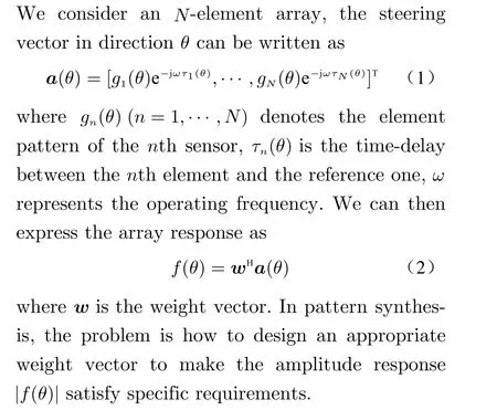
Array pattern synthesis (also called beamforming) is an important research direction in array processing. It is a signal processing technology that uses sensor arrays to send and receive signals directionally. Pattern design and synthesis play an important role in the high performance of the array system. For example, in a radar system, it is usually necessary to form a deep null in the interference direction to achieve interference suppression. In some communication systems, it is necessary to design a multi-beam pattern to realize data transmission to multiple users. In satellite remote sensing applications, it is necessary to design a wide main lobe pattern to expand the detection area. In pattern synthesis, antenna weights need to be designed so that the resulting pattern meets specific requirements.Pattern synthesis can be used on both the signal transmitting end and the signal receiving end.With the complexity of the electromagnetic environment, how to design a directional pattern that is flexible, robust, fast, and meets specific hardware requirements has important theoretical and application values.
In the past few decades, beampattern synthesis has received extensive attention from scholars at home and abroad, and many direction beampattern synthesis technologies have emerged one after another. The classical algorithms [1-3] have given the closed-form expressions, however, they are limited to some specific array geometries or array patterns. In order to realize a pattern synthesis method suitable for arbitrary arrays, scholars propose a global optimization solution based on random methods such as genetic algorithm (GA) [4], particle swarm optimization (PSO) method [5] and simulated annealing (SA) method [6]. However, since the above method requires a global search, it is usually computationally expensive. Especially when large-scale arrays are used, the global search method needs to take a long time to obtain satisfactory pattern results. Another type of pattern synthesis method [7-10] is based on the principle of adaptive array[11-13]. In this type of method,virtual interference is added iteratively to minimize the deviation between the synthesized pattern and the desired pattern. It should be noted that the existing directional patterns based on adaptive array theory comprehensively use empirical methods [8-10] to select interference power,and cannot accurately control the level of a given direction.
More recently, a scheme of zeroing the pattern based on the selection of antenna elements has been proposed in [14,15]. This type of method uses the state switching of the radio frequency (RF) switches to control the beampattern. In [16], the concept of the almost difference sets (ADSs) has been proposed. It is used to design the pattern of sparse planar array. The peak sidelobe level (PSLs) can be predicted by using the almost difference set and the array spectrum, so that low sidelobe pattern synthesis can be realized. In [17], a new sparse regularization method is used to realize the pattern synthesis of continuous cluster arrays. A maximum efficiency pattern synthesis method utilizing generalized eigenvalue decomposition is proposed in[18]. It should be noted that the above methods in [14-18] use empirical methods to select interference power, it is impossible to accurately control the level of a given direction.
Another type of pattern synthesis algorithm is implemented based on convex optimization theory[19]. For instance, in [20], the pattern synthesis problem is modeled as a convex optimization problem, and on this basis, the interior point method is used to solve the problem. However,this method is only suitable for some specific pattern synthesis problems. When the desired pattern contains the lower limit constraint requirements, the problem obtained is usually non-convex, so that convex optimization theory cannot be used to model and solve the problem. In order to realize the synthesis of the directional pattern when the lower limit of the level is included,in [21], they consider symmetric linear and planar arrays, and convert the non-convex problem into a convex problem by introducing a conjugate symmetric weight vector, thus realizing the lower limit of the level under the special array. In [22],the idea of semi-definite relaxation (SDR) [23] is introduced into the pattern synthesis. The nonconvex pattern is integrated for relaxation modeling. This scheme uses an iterative method to solve the weight vector, thereby reducing the relaxation error caused by the relaxation operation.However, since the relaxed problem is different from the original problem, the semi-definite relaxation can only get an approximate solution.There are also some convex optimization methods[24-26] that use the toolkit[27] to solve. In addition, some scholars respectively proposed the use of least squares method[28, 29], Fast Fourier Transformation (FFT) [30], and excitation matching method [31] to solve the problem. It should be pointed out that none of the above methods can achieve precise directional control.Therefore, even if there is a slight change in the desired pattern, the above methods need to redesign the pattern. In this paper, we give an overview about the accurate array response control based pattern synthesis algorithms.
2 Array Response Control (ARC)
In this section, we review the work of pattern synthesis using array response control firstly.Then we will introduce several algorithms of accurate array response control.
2.1 Adaptive Array Theory
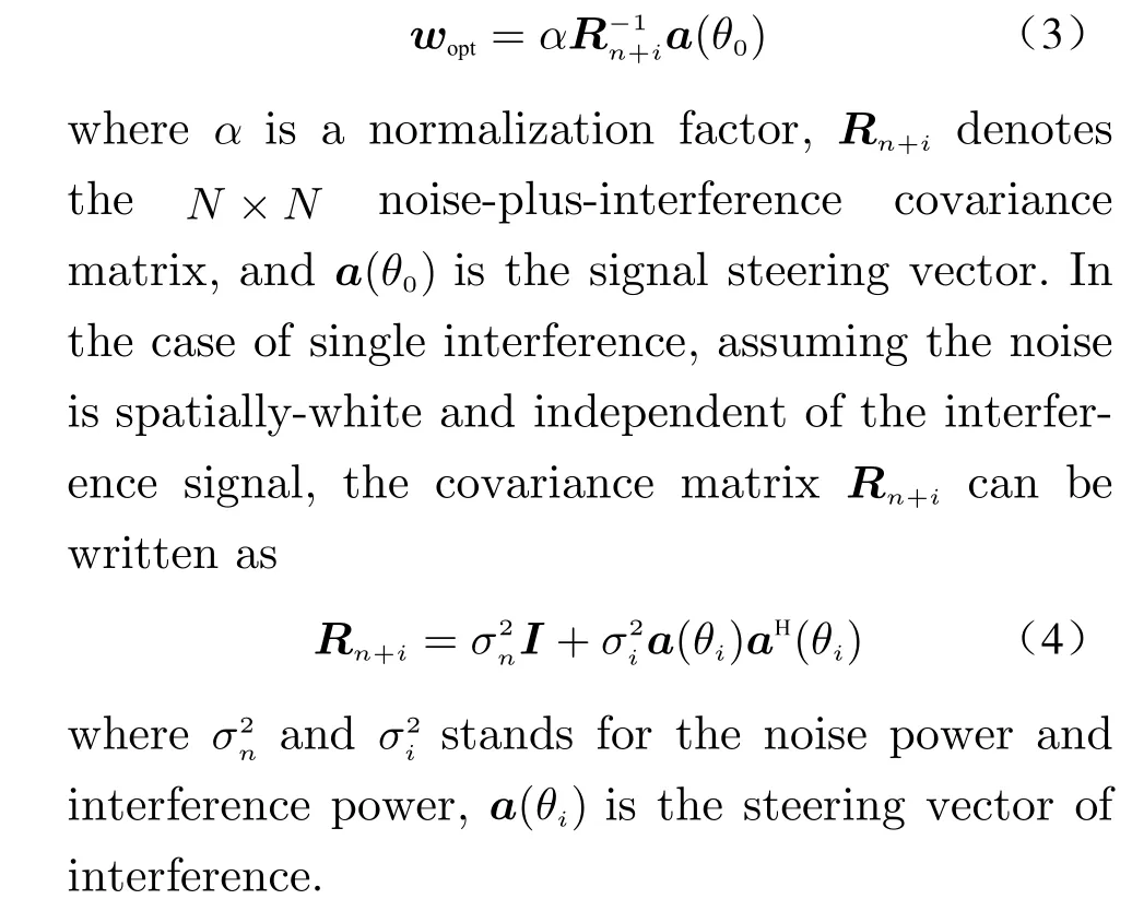
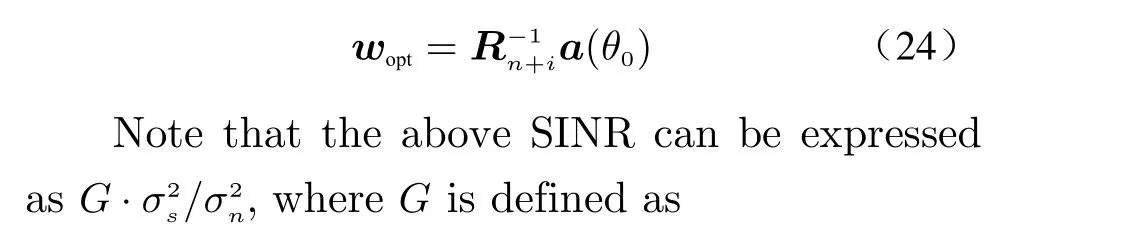
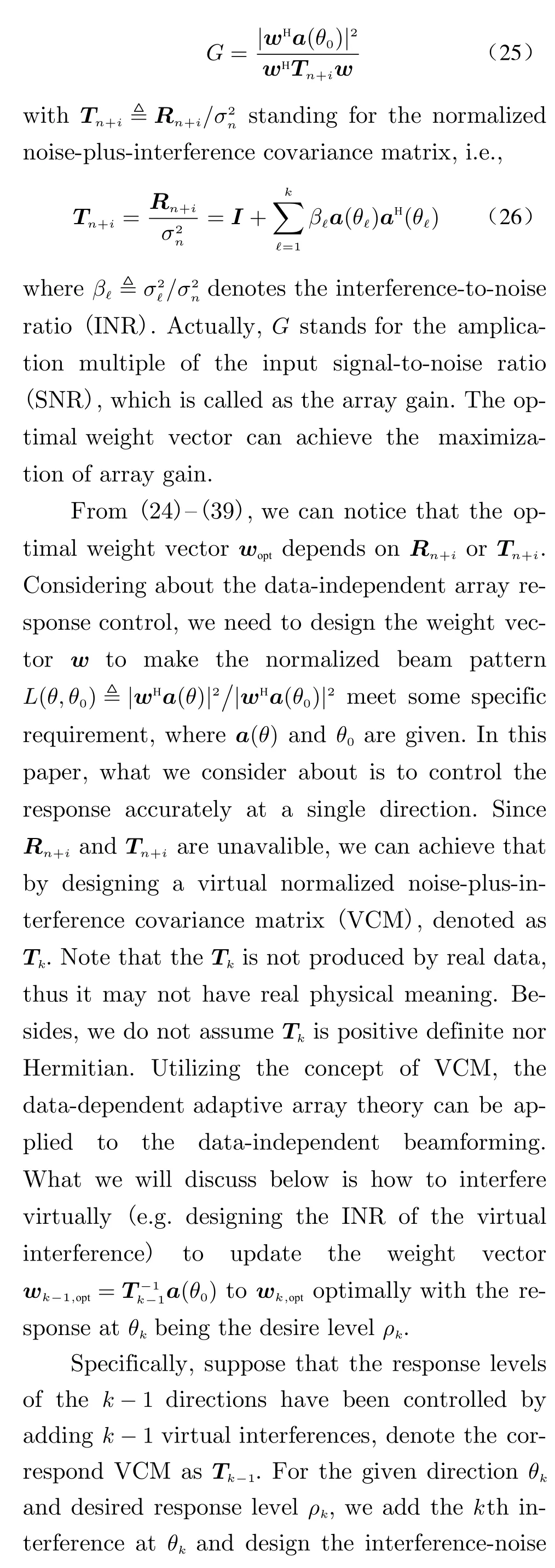
According to the theory above, the weight vector w can be optimally obtained by maximizing the output signal-to-interference-plus-noise ratio (SINR). In this case, the optimal weight vector woptcan be expressed as
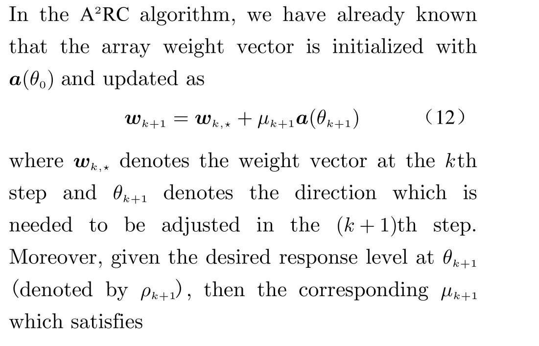
2.2 Accurate ARC (A 2RC)[32]
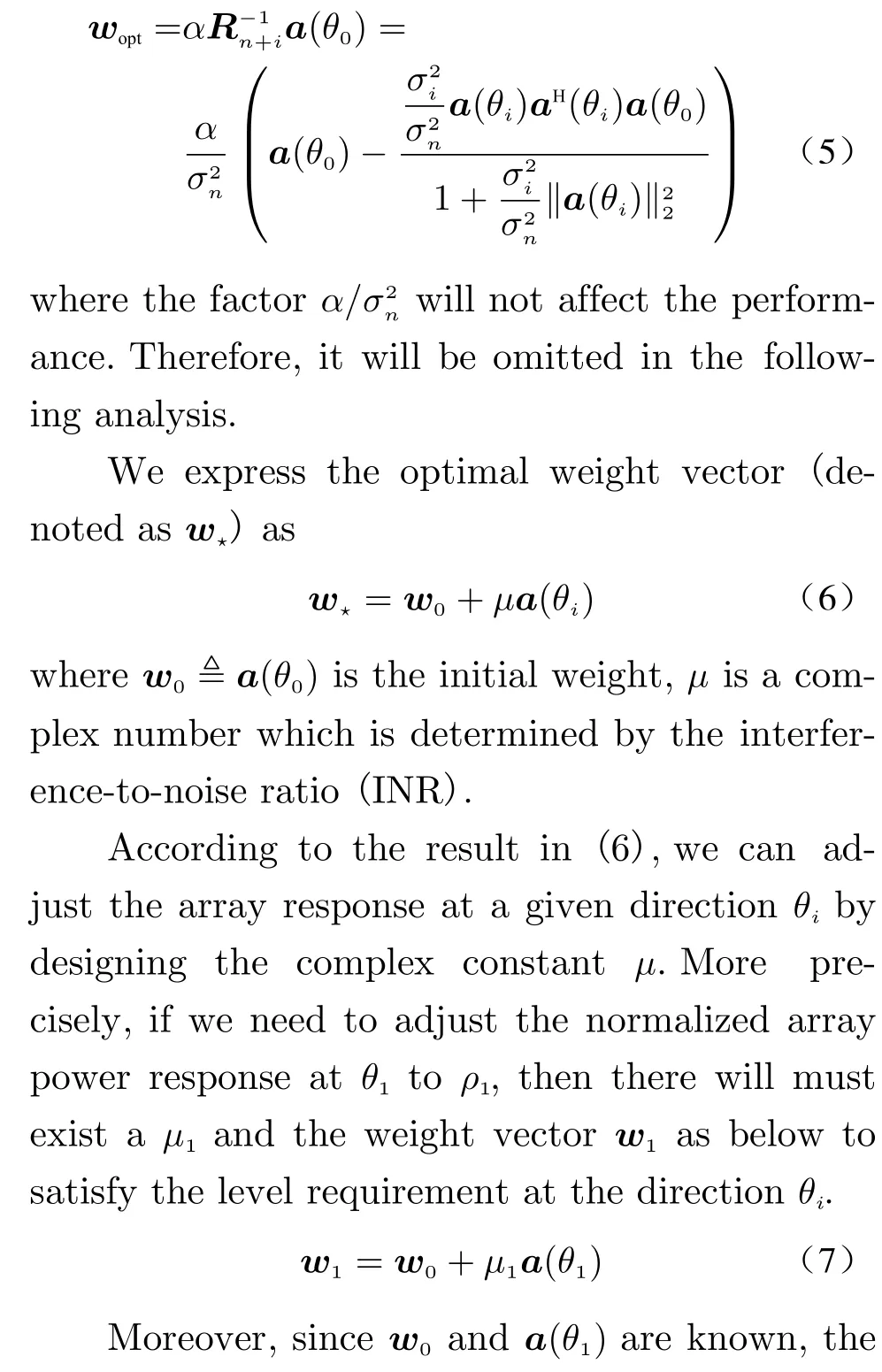
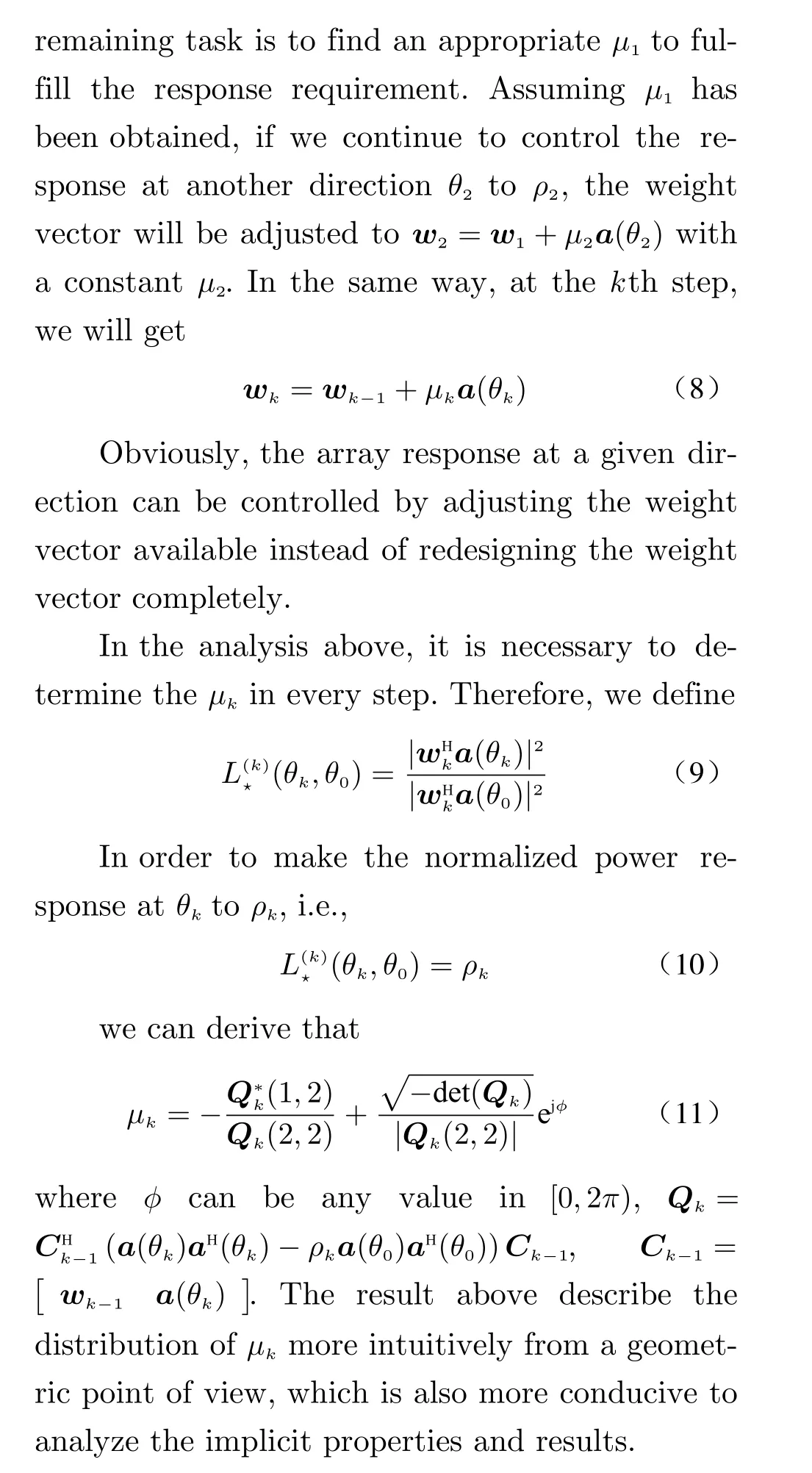
If we apply the matrix inversion principle, the weight vector in (3) can be rewritten as
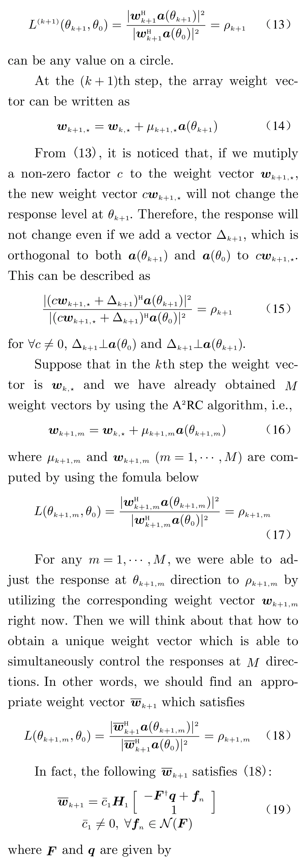
2.3 M A2RC and M 2A2RC[33]
2.3.1 MA2RC

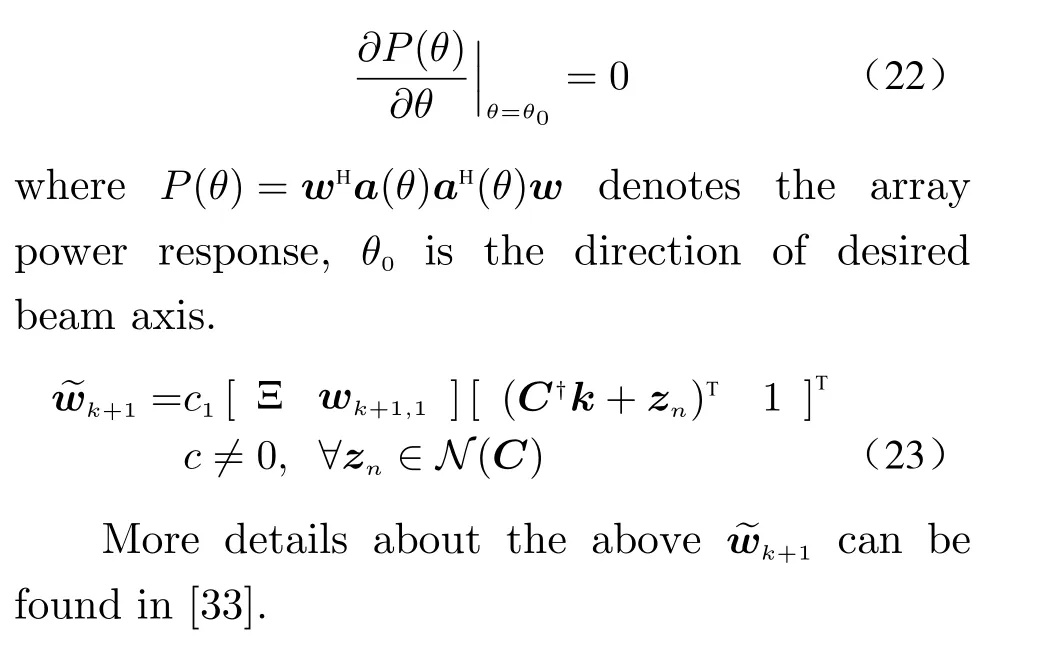
More precisely, we consider about adding a derivative constraint in the basis ofMA2RC which is expressed as
2.4 Optimal and Precise Array Response Control (OPARC)[34, 35]
It is known that the optimal weight vector wopt,which maximizes the SINR, is given by [11]
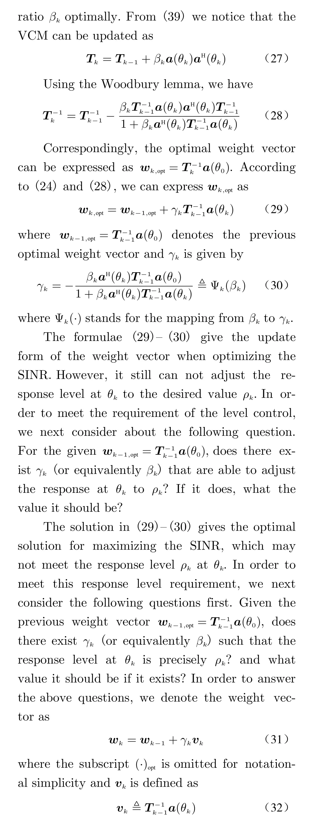
2.5 Weight Vector Orthogonal Decomposition(WORD)[36]

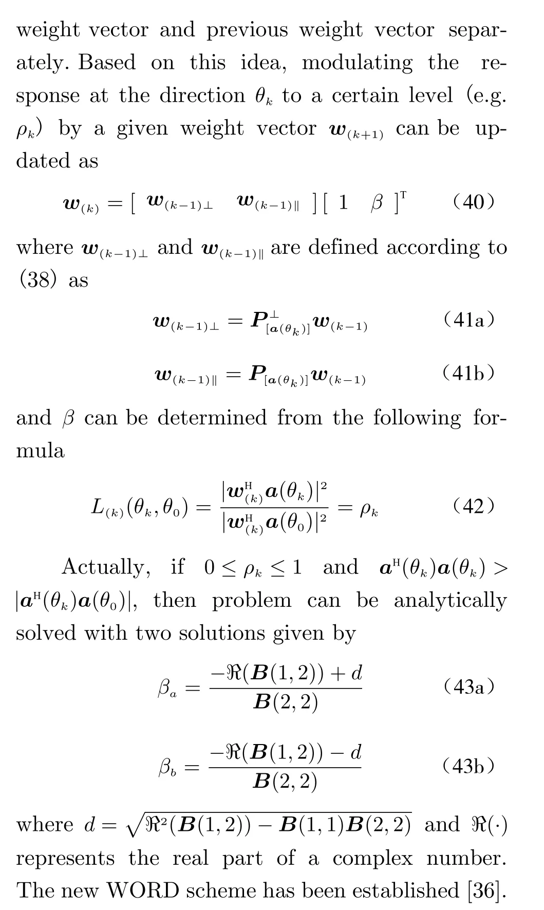
2.6 Complex-Coefficient WORD(C2-WORD)[37]
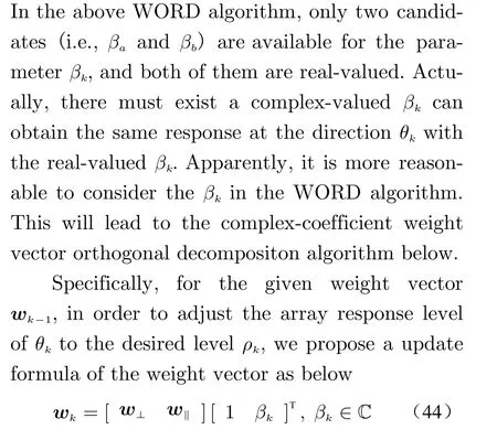
Different from the weight vector update of WORD in (40), the parameter βkin (44) can be complex-valued.
2.7 Robust C2-WORD[37]
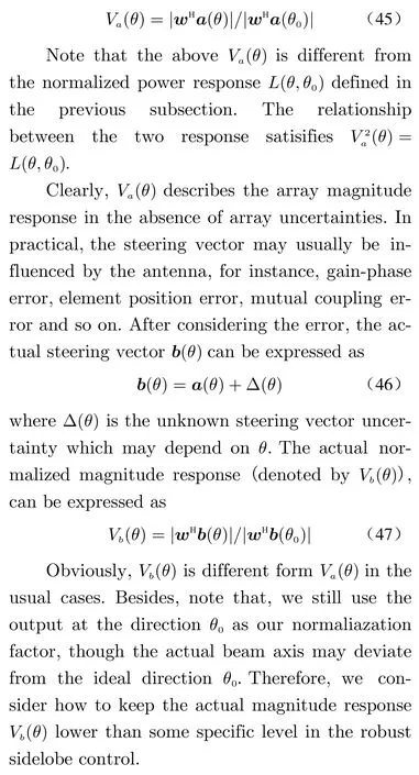
The C2-WORD algorithm developed in the previous subsection can control the array response level of a given direction in the absence of steering vector uncertainties. In order to realize array response control in the case where steering vector is present, the next problem is the robust sidelobe control. For the convinience of later derivations, we first define the normalized amplitude response as below
To proceed, we present a boundary analysis on the actual magnitude response Vb(θ) firstly.Next, we reasonably assume that the norm of the uncertainty vector Δ (θ) is
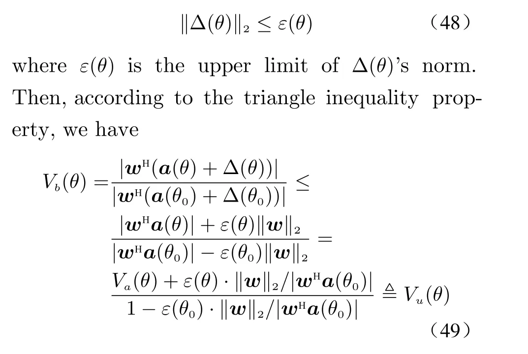
and
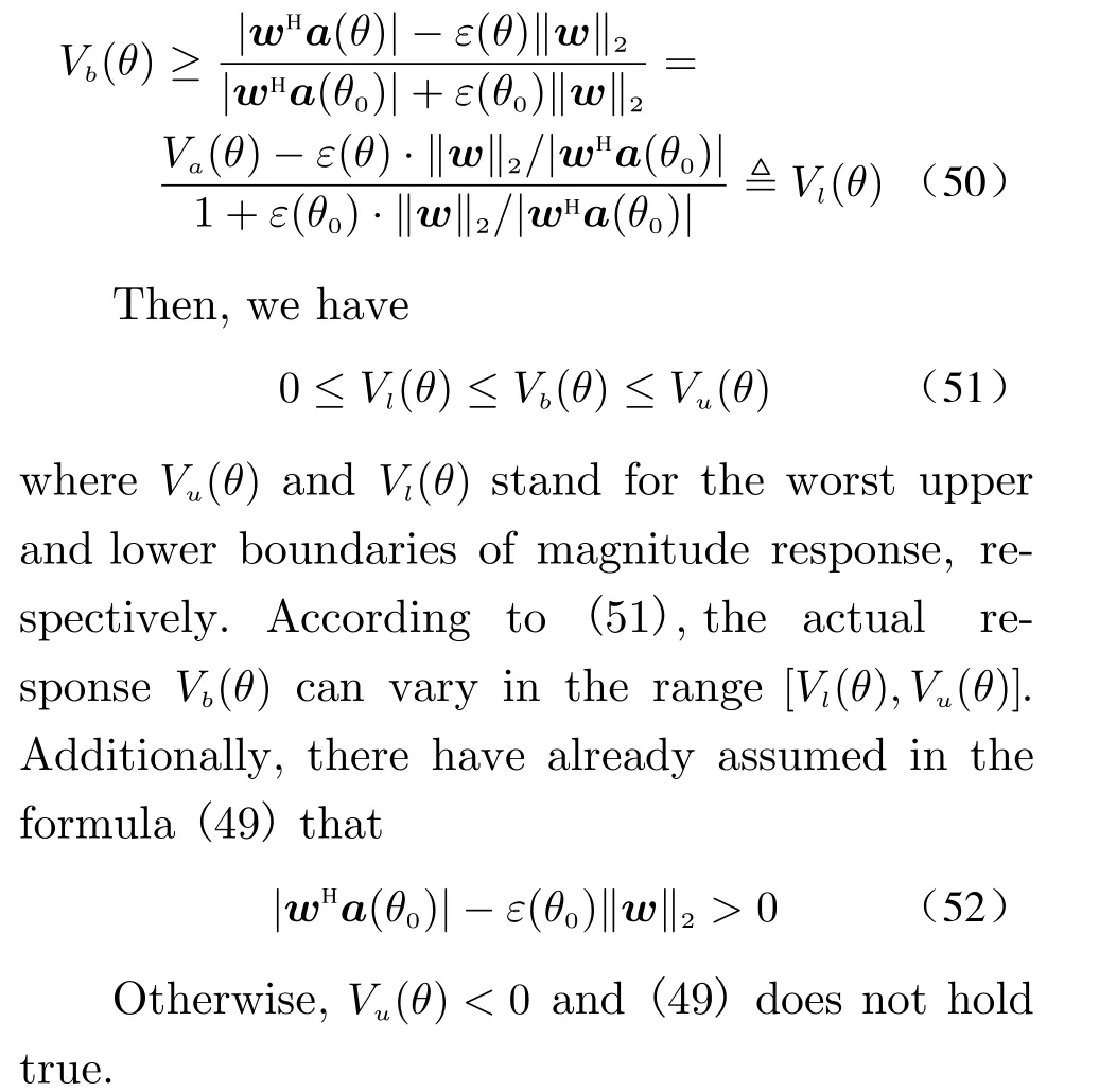
In the previous subsection, a boundary analysis on the array response is presented. In this subsection, we focus on the robust one-pointsidelobe control, i.e., making the response level of a actual sidelobe level lower than a specific value in the presence of steering vector uncertainties.
More specifically, we denote the desired magnitude response as Vd(θ). Give the previous weight vector wk-1and a sidelobe angle θkto be controlled, where k stands for the kth step. We need to find a new weight vector wkthat makes the actual magnitude response level of θklower than Vd(θk).
To simplify notations, we still use the symbol and meaning of Va(θ), Vb(θ), Vu(θ), Vl(θ) in the two preceding subsections, to describe the amplitude pattern corresponding to wk. Then, the problem of one-point robust sidelobe control can be formulated as

2.8 Flexible Array Response Control via Oblique Projection(FARCOP)[38]
Suppose that the noise is spatially-white andQ independent interferences. Then, the normalized noise-plus-interference covariance matrix is given by

In order to obtain the corresponding data matrix, the concept of virtual normalized noiseplus-interference covariance matrix (VCM) was proposed in [34]. The analysis shows that the pattern level at some direction can be adjusted by imposing virtual interferences. However, it is tough to caculate the power of corresponding virtual interference, which is mainly because of the non-correspondence (interactive influence)between the array pattern response and the INR.To avoid the disadvantage above, we porpose a flexible algoirthm of pattern control.
To begin with, we rewrite the normalized covariance matrix in (54) as
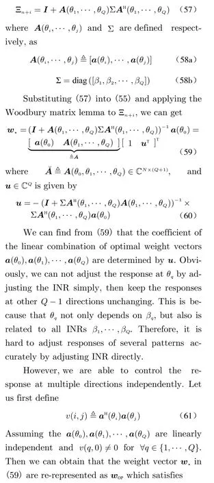

In the previous subsection, we obtain the equivalent representation of the optimal weight.Next we will parameterize the weight vector and propose the FARCOP algorithm.
For the sake of notational simplicity, we first define
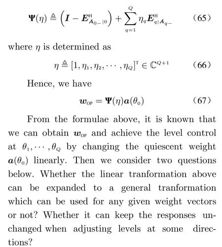
The formula (67) provides us a new view in the array response control of multiple points. It shows that we can control the response level at some specific angles by the linear transformation of the the given weight vectors. On the basis of(67), we introduce the FARCOP algorithm next,to achieve the array response control based on the given weight vector wpre.
More specifically, for a given wpre, we consider about looking for nex weight vector wnewto adjust the response levels at θ1,θ2,··· ,θQto ρ1,ρ2,··· ,ρQ. In the FARCOP algorithm, we tranform the wnewlinearly and consruct a new weight vector wnewby

where the transformation matrix Ψ(η) is given in(65), and ηq(q =1,··· ,Q) is a constant to be determined.
3 Simulations
In this section, representative simulations are presented to illustrate the application of the proposed FARCOP algorithm to array pattern synthesis. Various approaches, including the convex programming (CP) method, the A2RC method,the MA2RC method and the multiple-point OPARC method, are compared.
3.1 Nonuniform Sidelobe Synthesis for a Large ULA
In this subsection, consider a uniform linear array with N =100 elements, whose element spacing is half of wavelength. The desired pattern steers to θ0=60°with nonuniform sidelobe levels.Specifically, in the region [-20°,30°], the upper level need to be -45 dB, meanwhile, the level need to be - 35 dB in the rest of the region. It can be seen that, the desired pattern is similar to a Chebshev pattern with a -35 dB uniform sidelobe to some extent. Therefore, we utilize the initial weight of the FARCOP algorithm as the Chebshev weight with a -35 dB sidelobe attenuation, so that to simplify the synthesis procedure.
Under this assumption, we chooseQk=41 sidelobe peak angles in each step, then use the FARCOP algorithm to adjust their corresponding level to the desired response level. Since Q ≪N, the calculation in each step is reduced greatly. In addition, the array is centro-symmetric and the initial weight vector is conjugate centro-symmetric. We take the optimal parameter vector η⋆by (51) and obtain a weight vector which has a closed-form expression in each step of response control. Hence, the computation complexity of the proposed algorithm is further reduced. Results are shown in Fig. 1, we can see that only k =9 steps are required to synthesize a satisfactory beampattern.
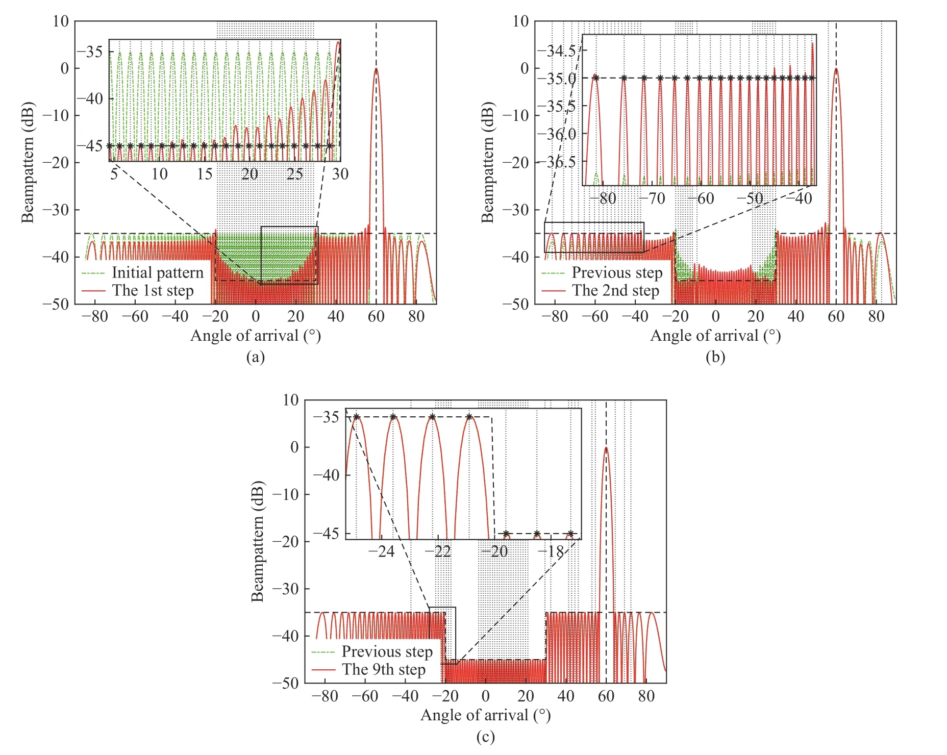
Fig. 1 Resultant patterns at different steps when carrying out a nonuniform sidelobe synthesis for a nonuniform linear array: (a) synthesized pattern at the 1st step; (b) synthesized pattern at the 2nd step; (c) synthesized pattern at the 9th step
In order to have fairer comparisons, we take the same number of the iterations steps, i.e.,k =9 steps when we use the MA2RC method [33]and the multi-point OPARC method [35]. The number of the selected angles in each step is also set as Qk=41. From the results in Fig. 2, we can see that the pattern envelope of CP method is not aligned with the desired one, where we can tell that the CP method are not able to control the beampattern according to the requirement.Besides, it is seen that the MA2RC and the FARCOP algorithm perform better than the A2RC algorithm (after 300 iteration steps). Additionally,we notice that the sidelobe level of the multipoint OPARC algorithm is higher than our desired level at some angles which is mainly because the multi-point OPARC algorithm is initialized by quiescent pattern instead of the Chebshev pattern that is coloser to the desired level.Hence, more iteration steps are needed in the application of the multi-point OPARC algorithm to ahcieve the desired pattern synthesis.
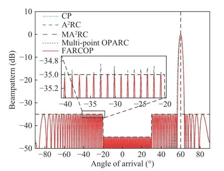
Fig. 2 Synthesized patterns for a large ULA
3.2 Uniform Sidelobe Synthesis for a Nonisotropic Random Array
In this subsection, we consider a linear random array with 21 elements. The pattern of the nth element is given by
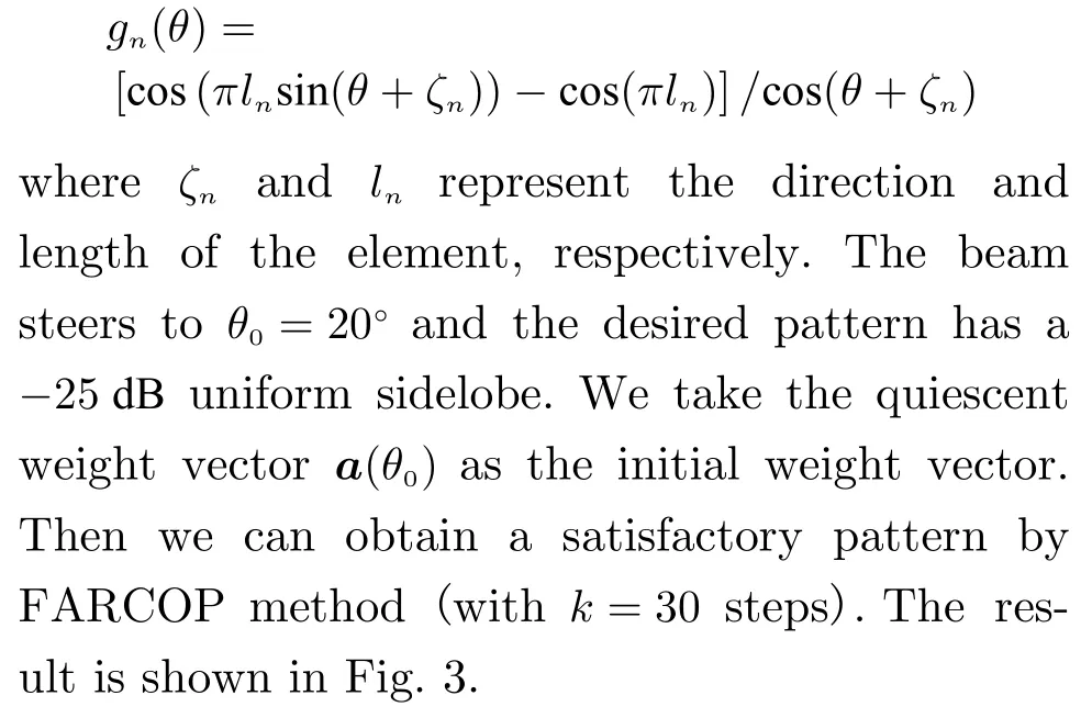
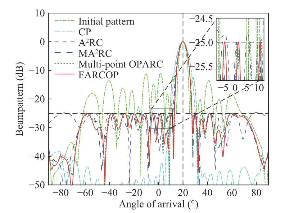
Fig. 3 Synthesized patterns with uniform sidelobe for a nonisotropic array
Notice the region [-5°,10°], we can see that both the A2RC algorithm (with 200 iteration steps) and the multi-point OPARC algorithm(with the same step number as FARCOP) produce responses that are higher than the desired levels at certain angles. Naturally, it may require more synthesis steps for these two methods to achieve satisfactory beampatterns. The CP method leads to a pattern with sidelobe much lower than the prescribed level. For the proposed FARCOP algorithm, Fig. 3 shows that the envelope of the synthesized pattern is aligned with the desired pattern. Moreover, it takes shorter time than MA2RC (with the same step number as FARCOP) to synthesize a satisfactory beampattern.
 Journal of Beijing Institute of Technology2021年1期
- Journal of Beijing Institute of Technology的其它文章
- MIMO Radar Waveform Design: An Overview
- A Brief Introduction on Joint Radar and Communication Systems
- QoS-Aware Power Allocation Scheme for Relay Satellite Networks
- System Design and Signal Processing for Frequency Diverse Array Radar
- A New Transmit Beamforming Method for Multi-User Communication in Dual-Function Radar-Communication
- Dual-Use Signal Design for Radar and Communication via Joint Orthogonal Signal and Phase Modulation