
Dual-Use Signal Design for Radar and Communication via Joint Orthogonal Signal and Phase Modulation
2021-05-13 03:51:46YuLinYiBuHuiQiuXueYaoXianxiangYuGuolongCui
Yu Lin, Yi Bu, Hui Qiu, Xue Yao, Xianxiang Yu, Guolong Cui
Abstract: This paper proposes a new information modulation resorting to orthogonal signal and its phase for dual-function radar communication (DFRC) systems. Focusing on the standardized linear frequency modulation (LFM) signal by additional phase, a bank of signals enjoying satisfactory autocorrelation and cross-correlation characteristics, are generated. Then, these signals map the different information as well as their phases are also modulated to increase the communication bit rate, thus yielding a series of dual-use signals. Finally, the radar detection and communication performance of dual-use signals are also provided through numerical simulation and half-physical platform verification, confirming the effectiveness of the designed signals compared with the existing design strategy.
Keywords: dual-function radar communication (DFRC); dual-use signal; joint orthoganal signal and phase modulation
1 Introduction
With the progress and innovation of science and technology, the availability of the radio spectrum has become more and more limited, and commercial communication services have also developed rapidly. They are putting the electromagnetic sensing modality systems, such as radar, under immense pressure[1]. Dual-function radar communication (DFRC) systems use the same platform and share the same hardware and spectral resources[2], which have the potential to save resources of hardware, reduce the interference of radar and communication systems and promote spectrum efficiency. Therefore, DFRC has attracted widespread interest from the researchers in radar[3], communications[4], Internet of things[5], intelligent transportation[6], and many other fields. Some interesting review articles on DFRC can be found in [7-9].
The performance of a DFRC system is highly dependent on the dual-use signal. A convenient method is mixed modulation of existing signals via invoking degrees of freedom in different dimensions[10], which can be divided into two categories. One is that existing communication signals are employed by researchers for realizing radar function. For example, the orthogonal frequency division multiplexing (OFDM) signal has been widely used in multicarrier DFRC[11-16]. However, the peak average power ratio(PAPR) of OFDM is very high that serious signal distortion is inevitable. Consequently, the performance of radar detection and communication will be weakened. The other utilizes existing radar signals to realize information transmitting.Different communication information can be distinguished through invoking degrees of freedom,such as time[17], chirp diversity[18], carrier frequency[19], etc. However, the communication bit rate is limited as one time-agile modulation signal only corresponds to one communication symbol. For example, in [20], a dual-use signal cluster based on phase or chirp rate modulated LFM signal is proposed. The dual-use signals in the signal cluster are orthogonal to each other and each of them can transmit a communication symbol.An efficient approach to improving communication bit rate is to design more orthogonal signals.However, it is hard to generate so many orthogonal signals.
A new dual-use signal design for radar and communication via joint orthogonal signal and phase modulation is proposed in this paper. Compared with the dual-use signal via orthogonal signal modulation proposed in [20], different phases are embedded in orthogonal signals. Not only the orthogonal signals but also phases can transmit communication information. Thus, the new dualuse signal via joint orthogonal signal and phase modulation can improve the communication bit rate. What’s more, joint orthogonal signal and phase modulation can decrease the bit error rate(BER). Because joint modulation uses Gray code, which can increase fault tolerance between adjacent bits. The numerical simulation and halfphysical platform verification are provided to illustrate the effectiveness of the proposed design.
The rest of this paper is organized as follows.In Section 2, DFRC architecture and signal model are presented. Then, design of dual-use signal and information modulation are derived in Section 3. Next, radar detection processing and communication demodulation processing are presented in Section 4. Then, numerical simulation and half-physical platform verification are presented in Section 5. Finally, some concluding remarks are provided in Section 6.
2 DFRC Architecture and Signal Model
Consider a dual-use radar and communications(RadCom) system which can realize target detection and communication simultaneously[21].The operating procedure of RadCom system and the cooperative communication system is summarized as Fig. 1. First, according to the transmitted communication information, the waveform generator generates corresponding dual-use baseband signal. Next, the signal is amplified before transmitting. Thus, not only can the Rad-Com system detect the target, but also the cooperative communication system is able to demodulate the communication information.

Fig. 1 Operating procedure of the RadCom system and the cooperative communication system
In this paper, we present a new information modulation method using orthogonal signals and their phases. Specifically, assuming that a communication symbol of P bits is required to transmit, the first L bits are represented by the orthogonal signals, and the last P -L bits are represented by the modulated phase. Thus, the number of the orthogonal signals is M =2L, and the number of different phases is I =2P-L. The possibility of transmitted symbol is M I. Mapping relationship between communication information and dual-use signals is summarized as Fig. 2. Assume that the pulse repetition time (PRT) of the transmitted signal is Trand each PRT transmits a dual-use signal. Communication bit rate will be R1=P/Tr. If we only use orthogonal signal modulation, communication bit rate will be R2=L/Tr. Evidently, we have R1>R2, exhibiting the joint modulation method may improve the communication bit rate.
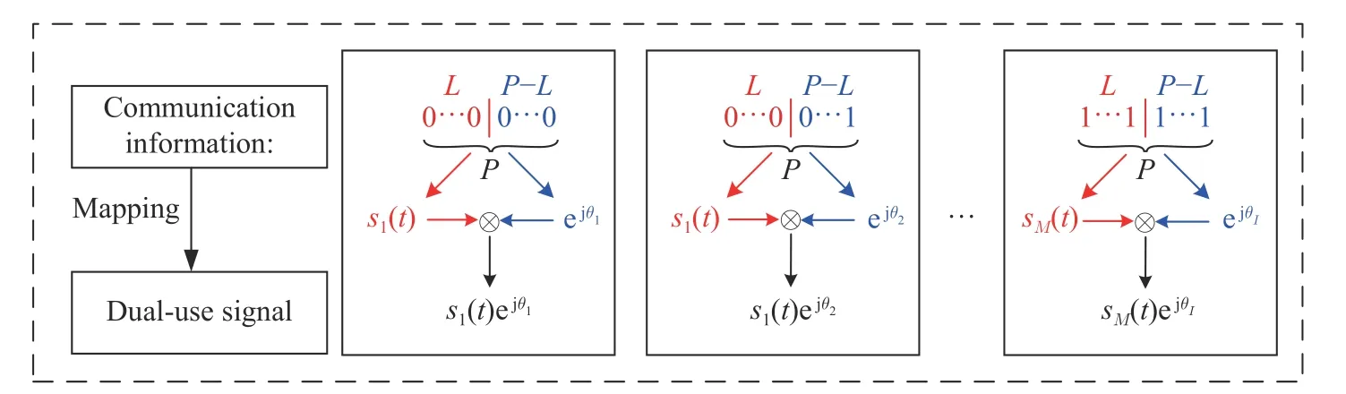
Fig. 2 Mapping relationship between communication information and dual-use signals
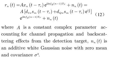
Assume that the target is located within the main lobe, the baseband signal received by the RadCom system is given as

where α is a constant complex parameter, n is an additive white Gaussian noise with zero mean and covariance
Usually, the received echo is processed by matched filter in order to weaken the impact of white Gaussian noise. More importantly, the good auto-correlation side lobe property of s,namely low auto-correlation peak side lobe level(APSL), can weaken the impact of other false or strong targets. Otherwise, excessively high APSL of the transmitted signal s will affect the correct detection of the target, and may even overlap with other signal cross-correlation side lobes to produce false target spikes[22].
For the cooperative communication system,the received baseband echo can be given as
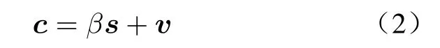
where β is a constant complex parameter, v is an additive white Gaussian noise with zero mean and covariance.
In the communication receiver, we need to design a demodulation approach to achieve the information extraction. The specifical demodulation procedure will be introduced in the subsequent section.
3 Design of Dual-Use Signal and Information Modulation
This section considers the design of orthogonal signals and then introduces the information modulation method based on orthogonal signal and its phase.
3.1 Orthogonal Signal Design and Modulation
Assuming that a communication information symbol of P bits is required to transmit, the first Lbits of communication symbol are represented by orthogonal signals. Mapping relationship between communication information and orthogonal signal is summarized as Fig. 5. The orthogonal signals used in this paper are composite linear frequency modulation (CLFM) signal clusters. CLFM signal refers to a signal which adds a time-varying phase disturbance to the standardized LFM signal. Multiple additions of different phase disturbance functions can produce CLFM clusters. CLFM signal can be expressed as


In order to ensure that the orthogonal signals have good performance of radar detection and communication at the same time, the constraints between APSL and CPSL can be expressed as
3.2 Phase Modulation
Assuming that a communication information symbol of P bits is required to transmit, the last P -Lbits of communication symbol are represented by modulated phases. In this section, the phase modulation process will be explained. Specifically, assuming that the number of modulated phases is I =4, the phase modulation combines orthogonal signals with the differential quadrature phase shift keying (DQPSK), as shown in Fig. 3.
More concretely, the last P -L (in this case,P -L=2) bits of the communication symbol are expressed as a bit pair {an}. Firstly, convert{an}to Gray code {bn}. The conversion rules of Natural code and Gray code are shown in Tab.1.
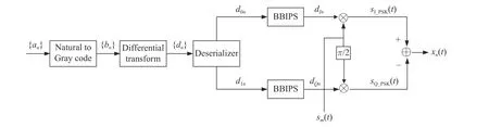
Fig. 3 Joint information modulation of four phase and orthogonal signals
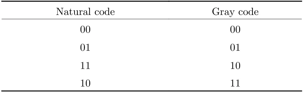
Tab. 1 Conversion rules of Natural code and Gray code

4 Radar Detection Processing and Communication Demodulation Processing
Assuming that the transmitted signal consists of NPRT, the pulse repetition time (PRT) of the transmitted signal is Tr, each PRT transmits a dual-use signal, the distance of target is R, corresponding time delay τr=2R/c (c is the velocity of light), the velocity of target is v, corresponding Doppler frequency fd=2v/λ (λ is the wavelength of radar system), the baseband echo of the n- th (( 1 ≤n ≤N)) PRT can be expressed as
4.1 Radar Detection Processing
The radar signal processing is shown in Fig. 4.Each dual-use signal in the echo is filtered with the corresponding orthogonal signal. The pulse compression result of the n-th PRT is given as
Since each dual-use signal has good autocorrelation characteristics, it can correctly detect the target. According to the location of spikes,the pulse compression results of every PRT are aligned. Then, perform moving target detection(MTD) [23] processing in the slow time domain.Finally, the range-Doppler plane can be obtained.

Fig. 4 Radar signal processing
4.2 Communication Demodulation Processing
As to the communication demodulation processing, it includes orthogonal signal demodulation processing and phase demodulation processing respectively. The orthogonal signal demodulation processing is shown in Fig. 5. Take the n-th PRT for example. Assume that the orthogonal signal used in the n-th PRT is sm(t).First, use a set of filters to process the baseband echo of the n-th PRT, which is described in Eq. (12). The impulse responses of these filters are hn(t)=s*n(-t),1 ≤n ≤M. Since the designed orthogonal signals have good cross-correlation characteristics, only the pulse compression result of rn(t) and s*m(-t) has a higher target spike. Thus, the orthogonal signal sm(t) is selected based on an energy detector. The modulated orthogonal signal in the n-th PRT is considered to be sm(t). Finally, the first L bits of the communication symbol are demodulated according to the mapping relationship.
In order to get the last P -L bits of the communication symbol modulated by the orthogonal signal's phase, we perform the phase demodulation processing, as shown in Fig. 6. For the baseband echo of the n-th PRT rn(t),n=1,··· ,N, assume that the maximum output of energy detector in orthogonal signal demodulation processing is zn(t),n=1,··· ,N. By performing phase extraction operation to the peak values of zn(t),n=1,··· ,N, we can obtain the phases θn,1 ≤n ≤N. and further get the phase differencesΔθn=θn-θn-1,1 ≤n ≤N(θ0=π/4). Then, according to DQPSK mapping rules in Tab. 2, we can obtain the Gray code bn.Finally, transferring the Gray code bnto Natural code an, the last P -L bits of communication symbol is estimated.
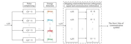
Fig. 5 Orthogonal signal demodulation processing
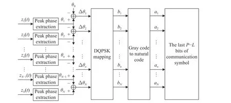
Fig. 6 Phase demodulation processing

Tab. 2 DQPSK mapping rules
5 Numerical Simulation and Half-Physical Platform Verification
This section assesses the parameter selections of orthogonal signals and the performance of the radar detection and communication on dual-use signal through numerical simulations. The results of half-physical platform verification are also provided.
Before proceeding further, the detailed illustration of half-physical platform is given. The half-physical platform verification scenario can be seen in Fig. 7. The left one is the half-physical platform equipment, and the right one is the dual-use signal. The half-physical platform is a combination of NI ’s PXle-5 785 and Labview.More correctly, the signal processing by the halfphysical platform is summarized as Fig. 8. First,because of the limitations of the half-physical platform, the dual-use signal is loaded with a carrier frequency to shift its spectrum to positive frequency. Then, in order to simulate radar echo,we add the target information such as distance and velocity in the dual-use signal. Next, extract the real part of the signal and load it to field programmable gate array (FPGA) system. Then,under the coordinated control of Labview, the system transform the digital signal to analog signal. After the analog signal is transmitted and received by the system, it is converted into digital signal again. Then, the real signal is transformed into complex signal through Hilbert transform,which is expressed as
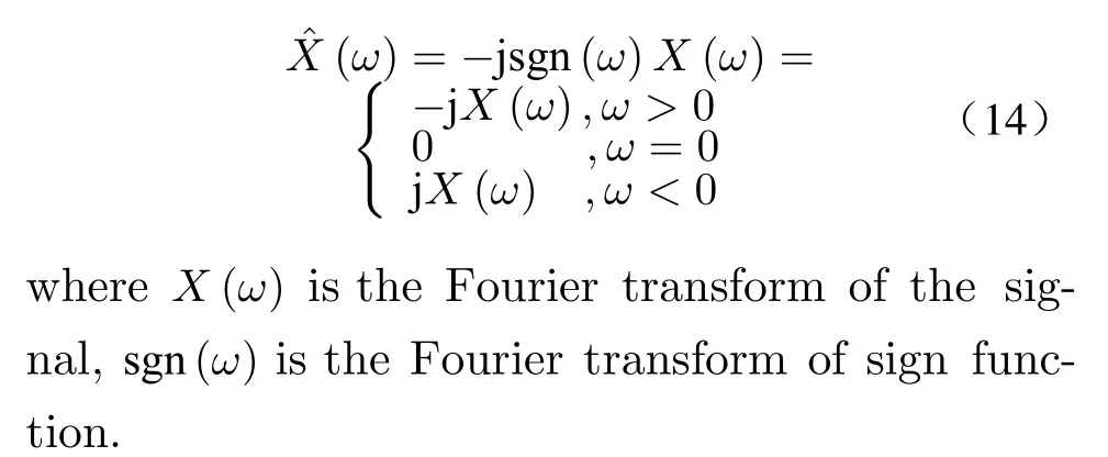
Finally, perform the signal processing in MATLAB and verify the radar and communication functions of the dual-use signal.

Fig. 7 Half-physical platform verification scenario
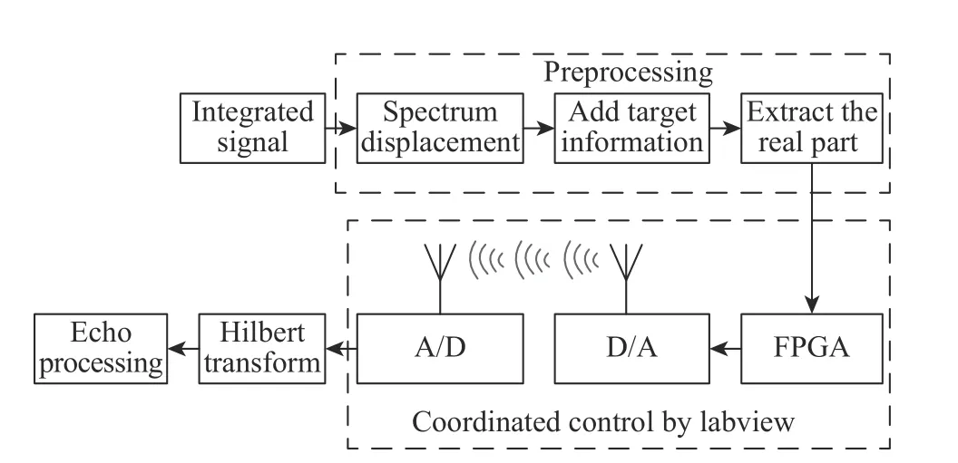
Fig. 8 Signal processing by the half-physical platform
5.1 Parameters Selections
Assume that the bandwidth of LFM signal is 30 MHz, the bandwidth of CLFM signal is 60 MHz,the duration of CLFM signal is 5 μs, ωmnis selected at equal intervals within the specified frequency band [0, 10 MHz], [10 MHz, 20 MHz],[20 MHz, 30 MHz], [0, 30 MHz]. The influence of N and ωmnon APSL can be seen in Fig. 9, and the influence of N and ωmnon CPSL can be seen in Fig. 10. From the simulation, for any frequency band, the normalized APSL level decreases as N increases, while the normalized CPSL level hardly changes. When N ≥100, even if N increases, the normalized APSL level will hardly change. In addition, the selection of different frequency band will also influence the normalized APSL level. For a fixed N, if the bandwidth is fixed, the higher the starting frequency,the lower the normalized APSL level. And if the bandwidth increases, the normalized APSL level will decrease.
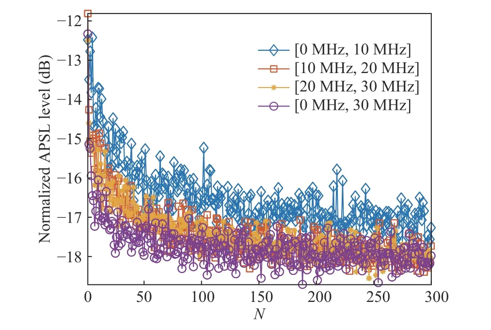
Fig. 9 The influence of N and ωmn on APSL

Fig. 10 The influence of N and ωmn on CPSL
5.2 Analysis of Radar Detection and Communication Performance
Assume that RadCom system transmits a piece of string information, which is ‘IloveChina’. According to the American Standard Code for Information Interchange (ASCII), the ASCII code of the string ‘IloveChina’ is ‘73 108 111 118 101 67 104 105 110 97’. The conversion relationship between character and dual-use signal is expressed as Tab.3. If P =7, L=5, the last P -L=2bits of the string is ‘01, 00, 11, 10, 01,11, 00, 01, 10, 01’. The Gray code {bn} of the last 2 bits is ‘01, 00, 10, 11, 01, 10, 00, 01, 11, 01’.The Differential code {dn} of the last 2 bits is‘10, 10, 11, 00, 01, 00, 00, 01, 10, 00’. Principle of quaternion differential encoding and decoding can be summarized as


Tab. 3 Conversion relationship between character and dual-use signal
Take the character ‘I’ for example. The corresponding 7-bit natural code is ‘1 001 001’. For the first 5 bits ‘10 010’, the decimal code is ‘18’,corresponding to orthogonal signal s19(t). For the last 2 bits ‘01’, transfer it to Gray code ‘01’.Then, convert Gray code ‘01’ to Differential code‘10’. ‘10’ maps phase θ3. Therefore, in order to transmit the information ‘I’, we can transmit the signal s19(t)ejθ3.
Assume that the bandwidth of LFM signal is 30 MHz, ωmnis selected at equal intervals within the specified frequency band [0,30 MHz], N is 300, the duration of dual-use signal is 5 μs, the bandwidth of dual-use signal is 60 MHz, the number of the PRT is 10, the distance of the target is 1 km, the velocity of the target is 500 m/s,signal noise ratio (SNR) is 0 dB. Radar detection results of numerical simulation and half-physical platform are summarized in Fig. 11 and Fig. 12. From the results, both of simulation and half-physical platform verification can detect the target. The distance is 1 km, which is equal to the true distance. The velocity is 498 m/s, which is closed to the true velocity.Both the results verify the radar function of the dual-use signal. Compared with simulation, the half-physical platform result has 7.96 dB loss, because the signal has a certain attenuation after passing through the closed-loop equipment.
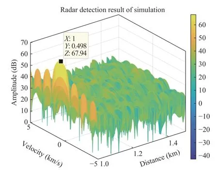
Fig. 11 Radar detection results of simulation
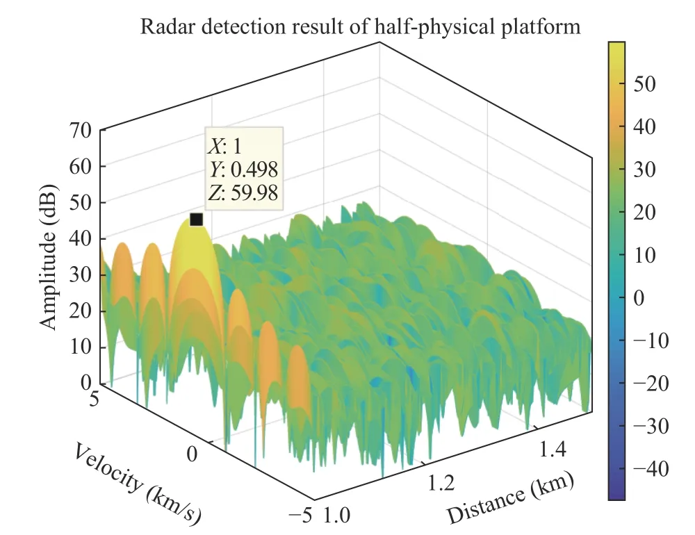
Fig. 12 Radar detection results of half-physical platform verification
The demodulation results of numerical simulation and half-physical platform verification are summarized in Tab.4 and Tab.5. Through demodulation, we can obtain the communication information ‘IloveChina’. Under the above parameters, communication information can be demodulated without distortion in both simulation and half-physical platform verification. However,SNR will influence the demodulation of communication information. If SNR is very low, BER will increase. Relevant parameters are consistent with the above. For each SNR, the demodulation is in the same condition and is independently executed 1 000 times. The relationship between BER and SNR is summarized in Fig. 13.For comparison purpose, we perform two methods. One is transmitting 7 bits information symbol via joint orthogonal signal and phase modulation. The other is only using orthogonal signal modulation to transmit. From the simulation,BER decreases as SNR increases. And for the same SNR, BER via joint modulation is lower than that via orthogonal signal modulation. Because the joint modulation uses Gray code, which can increase fault tolerance between adjacent bits.

Tab. 4 Demodulation results of simulation

Tab. 5 Demodulation results of half-physical platform verification
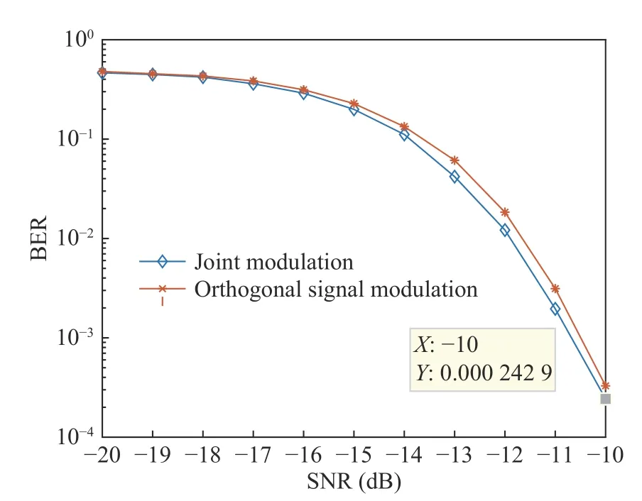
Fig. 13 Relationship between BER and SNR
6 Conclusion
This paper has proposed a new information modulation via orthogonal signals and their phases,where each orthogonal signal maps L bits communication symbol, and its phase can transmit extra P -L bits communication symbol. Compared with existing orthogonal signal modulation,the joint orthogonal signal and phase modulation improves the communication bit rate. The numerical simulation and half-physical platform verification have been performed. Results have shown that the designed dual-use signals can realize radar and communication functions. In addition, BER via joint modulation is lower than that via orthogonal signal modulation.
 Journal of Beijing Institute of Technology2021年1期
- Journal of Beijing Institute of Technology的其它文章
- MIMO Radar Waveform Design: An Overview
- Pattern Synthesis via Accurate Array Response Control: An Overview
- A Brief Introduction on Joint Radar and Communication Systems
- QoS-Aware Power Allocation Scheme for Relay Satellite Networks
- System Design and Signal Processing for Frequency Diverse Array Radar
- A New Transmit Beamforming Method for Multi-User Communication in Dual-Function Radar-Communication