
System Design and Signal Processing for Frequency Diverse Array Radar
2021-05-13 03:51:58JingweiXuLanLanXiongpengHeShengqiZhuCaoZengGuishengLiaoYuhongZhang
Jingwei Xu, Lan Lan, Xiongpeng He, Shengqi Zhu, Cao Zeng,Guisheng Liao, Yuhong Zhang
Abstract: Frequency diverse array (FDA) radar has been studied for more than 15 years and has attracted a lot of attention due to its potential advantages over the well-known phased array radar.The representative feature of FDA is range-angle-time-dependent transmit beampattern and its underlying properties are continuously revealed in the research. The formulation and exploitation of the transmit diversity with a frequency increment is the fundamental principle, which brings extra degrees-of-freedom (DOFs) in the transmit dimension. As the FDA radar carries additional information in range, it provides more flexibility in signal processing and also brings in new technical issues. This article overviews the state-of-the-art in FDA radar area and its applications, mainly based on the progress in our group. There are two main catalogs in FDA radar area, namely coherent FDA and FDA-MIMO(multiple-input multiple-output) radars. Potential applications including target parameter estimation, ambiguous clutter suppression, and deceptive jammer suppression are discussed.
Keywords: frequency diverse array (FDA); range-angle-time-dependent transmit beampattern;parameter estimation; ambiguous clutter suppression; deceptive jammer suppression
1 Introduction
Radar has been widely used in military and civil applications. Driven by the development of information processing and high-speed/super-largescale/field-programmable hardware technology, it is desirable and possible for modern radar systems to realize flexible transmit waveform agility,which greatly enhances adaptation ability to target and environment [1,2], enables cognitive radar design [3,4], and better maintains multifunction system [5,6]. Indeed, advances in radar technology are commonly enabled by the ability to control new degrees-of-freedom (DOFs), and each new generation of radar platforms requires fundamental advances in radar signal processing[7]. Among them, frequency diverse array (FDA)radar has attracted increasing attention because it provides enhanced flexibility of illumination beampattern and increased controllable DOFs in range dimension. Since the concept proposed by Antonick et al. [8-10], FDA has been studied for more than 15 years in different aspects, including transmit beampattern [11], array configuration design [12,13], parameter estimation [14-16],moving target indication (MTI) [17], clutter suppression [18,19], and interference mitigation [20].Basically, FDA radar is an effective implementation of waveform diversity and possesses several beneficial properties for performance improvement. It is distinguished by the increased dimensionality of the illumination pattern across the elements of the array.
Although the difference between FDA and phased array (PA) is as simple as using tiny increased instead of identical carrier frequencies across the array elements, it brings significantly electromagnetic difference between these two radar systems. The PA radiates angle-dependent beampattern which is independent of range/time,while the FDA radiates range/time-angle-dependent beampattern. A series of works are devoted to the beampattern synthesis and characteristic analysis in FDA radar framework. Because the range and angle information are coupled in the transmit beampattern using uniform frequency increments, it leads to a group of angle-range pairs that both match the echo from the target([21-25] and some references therein). To focus the transmit energy in a specific range-angle region, several methods to design the nonlinearly increased frequencies have been proposed, including the logarithmically increasing frequency offset [21], the random offset [26], the optimization methods based on the genetic algorithm [27],particle swarm optimization [28], the subarraybased FDA framework [29], and Taylor windowed frequency offsets [30]. In [31], a rangeangle decoupled beampattern model in a closed form was proposed to solve the problem, where a mathematically optimal method for FDA focusing beamforming was developed by introducing the beampattern area as a criterion. Although it is possible to realize range-angle focusing in the beampattern of FDA within a particular time instance by using non-regular frequency increment and array configuration, the cost of such scheme is energy dispersion. However, the time-variant beampatetrn still poses a challenge in target localization and other practical applications.Moreover, to address the time-variant issue, an compensated time-modulated optimized frequency offset scheme was introduced to generate a time-invariant spatial beam for a single-target in short-range [22]. The optimization of the sparse time-modulated optimized frequency offset frequency diverse array with time-invariant spatial-focusing beampattern was presented in[32]. The beampattern with a single maximum at the target location was designed in [33], where the time-invariant joint Tx-Rx beampattern design was considered based on the output SINR maximization. The exact time-range and frequency-phase relationships was presented in [34].An enhanced transmit-receive beamforming approach was proposed to achieve the time-invariant and symmetrical beampattern with only a single maximum value in range-angle space [35].In this article, we provide thorough understanding of FDA transmit beampattern as well as its physical viewpoint on transmit beampattern analysis.
Capitalizing the additional DOFs, a host of applications, ranging from remote sensing to communication systems, can benefit from the FDA, which can be summarized in the following categories: 1) By utilizing the DOFs both in the angle and range domains, the joint angle and range parameters can be unambiguously achieved[16]. The Cramér-Rao lower bound and mean square error expressions in multiple signal classification(MUSIC)-based range-angle estimation algorithms were derived in [36]. To reduce the computational complexity, a one-dimensional MUSIC algorithm for the joint angle and range estimation was proposed in [37]. The angle-range-Doppler estimation with transmit subaperturing FDA radar was proposed in [38], where the transmit weight matrix was designed for improved tracking performance. In [39], a gridless compressed sensing-based algorithm was proposed,where a 2-D atomic norm minimization (ANM)problem was formulated. 2) Furthermore, taking the advantage of range-angle-dependent beampattern, a range-ambiguous clutter suppression approach was devised, which consists of vertical spatial frequency compensation and pre-STAP filtering [40]. In [18], a range ambiguous clutter suppression approach was introduced with the FDA-STAP radar, where a secondary range dependence compensation (SRDC) approach is proposed to address the range dependence problem.An enhanced three-dimensional localization(3DL) based adaptive range-angle-Doppler processing method was devised in [19] to reduce the dimension of the processor. 3) Furthermore, several approaches have been considered to suppress the mainlobe deceptive jamming with FDAMIMO radar [20,41-45]. It is noteworthy that the signal model in [20] is a special case due to missing the time delay term. Besides, it is not feasible to find perfectly orthogonal waveforms for all Doppler and delay pairs in practice. The signal model has been re-derived in [41,42], where the estimation of jammer-plus-noise covariance matrix was addressed in [43]. The data-independent beamforming was performed to suppress false targets by nulling at the equivalent transmit beampattern with an appropriate frequency increment,where the responses of the beampattern were accurately designed to enhance the robustness of jammer suppression [44-46]. 4) Due to the ability of distinguishing the range ambiguous echoes in the spatial frequency domain in FDA radar,the range ambiguous echoes were compensated by range dependence compensation (RDC) technique, and the range ambiguous echoes can be separated by using a series of transmit beamformers, which can achieve the HRWS imaging[47]. In [48], an optimized receive beampattern was applied in each particular range region to extract the desired echoes from the presumed range region and suppress the undesired echoes from other range-ambiguous regions, achieving the high-resolution images of these range regions.Moreover, in [49], three adaptive GLRT-based detectors were designed for FDA-MIMO radar.
Active radar is used for collecting the backscattered electromagnetic wave transmitted by itself and determining whether a possible target is present or not, so does FDA radar. It brings new information in range because FDA radar introduces variation of beampattern in range, indicating that the core of FDA radar technique lies in how to make the best of the new range information. Generally speaking, this task cannot be fulfilled without jointly considering system design and the corresponding signal processing. Reasonable system design is the foundation for advanced signal processing techniques. There are two main catalogs of FDA radar frameworks in the literatures:
1) Coherent FDA radar [14,50]: The same baseband waveform is adopted for all array elements.
2) Orthogonal FDA radar [16-20]: Orthogonal waveforms are employed to the array elements.It is also known as FDA-MIMO radar in the literatures.
The main task is to make the best of the new information in range, however, the two FDA radar frameworks result in different system structures in transmitter and/or receiver as well as corresponding signal processing algorithms. There are two key questions involving FDA radar techniques. The first question is how to acquire such new information, while the second question is how this new information will be beneficial for target detection, parameter estimation, interference mitigation and other radar applications. To the best of our knowledge, there are some works answering the second question, including enhanced controllability of beampattern, improved target parameter estimation, and range-dependent interference cancelation. However, the first question, which is strongly based on system design, is still not clear, which will be discussed in this article. Moreover, the new range information of FDA radar is produced by the transmitter while signal processing is performed at the receiver, thus the system design and signal processing should take full consideration of the transmitter and receiver. We will provide realiable/practical system structures for the two FDA radar frameworks as well as the corresponding signal processing schemes and algorithms.
The objective of this article is three-fold:
1) Firstly, we aim to provide an overview of FDA radar and comment on the significance of current works in designing a practical system.The time-varying beampattern measurement is a great challenge for antenna design, which calls for more efforts. Nevertheless, a thorough understanding of its characteristic is helpful in designing a realizable/practical antenna measurement system. We will also provide explicit explanation on the requirement for FDA antenna in designing the ultimate FDA radar system.
2) Secondly, we will address coherent FDA and FDA-MIMO radars via providing concise system structures as well as fundamental signal processing schemes. As identical baseband waveform is adopted in the coherent FDA radar, it is difficult to obtain independent transmit DOFs. It is found that matched filtering in coherent FDA radar is also angle-dependent, which differs from that in the traditional PA radar. Besides, the range information is coupled with angle information and is not very easy to exploit. In FDAMIMO radar, the situation seems more optimistic. Since orthogonal waveforms are transmitted,it is possible to obtain independent transmit DOFs by using a series of matched filters corresponding to these waveforms. Note that the ideal orthogonal waveforms are not available. Nevertheless, for ground based radar system, the clutter is centralized at zero Doppler frequency and the signal of interest can be regarded as point source. In this case, orthogonal waveforms assumption is reasonable for further process. Concise system structure will be presented to describe the general signal model of FDA-MIMO radar, though the practical radar signal involves target, clutter, interference as well as system noise. It is emphasized that the range information in transmit steering vector of the FDAMIMO radar is different from that in traditional radar. In the traditional radar system, the time delay is used to estimate the range of target, i.e.,R=τc/2, where τ is the round-trip time delay of target echo and c is the speed of light. In contrast, in FDA-MIMO radar, the range of target can of course be estimated by the time delay, besides, it can also be obtained by proper spatial signal processing. Moreover, these two procedures can be complementary to each other, resulting in improved range estimation accuracy and resolved range ambiguity. Therefore, the novel range information in FDA-MIMO radar enhances the flexibility of signal processing. In the article, we will present the fundamental signal processing scheme of FDA-MIMO radar as well as practical issues which call for advanced signal processing techniques.
3) Thirdly, we intend to provide potential applications in the FDA radar. Several practical application scenario examples will be provided.Coherent FDA radar possesses the wide angular spatial coverage ability which is increasingly demanded in high-speed moving target detection and near-range air defense. In these situations, it is desired to illuminate the target with as long period as possible. FDA-MIMO radar can obtain independent DOFs in range, and thus to improve discrimination of target in range. For example, small target buried in the range sidelobe of large target can be detected, range ambiguous targets can be isolated with parameter ambiguity resolved, range ambiguous clutter can also be isolated and suppressed, and repeated and timedelayed jamming signals can be identified and mitigated.
The article provides a thorough understanding of FDA radar, covering its configuration for engineering implementation, signal processing schemes for performance improvement, and its potential applications in addressing bottlenecks in current radar systems. It is our expectation that this article will be of significant interest to both radar community and signal processing community in exploring its further potentials.We have several works that discuss the signal processing issues in FDA radars, all are based on system realizability consideration and practical application scenarios.
2 Coherent FDA Radar
2.1 Transmit Beampattern of Coherent FDA
Compared with the conventional phased array radar, the coherent FDA adds a small frequency increment over array elements. This slight difference causes sufficient change of the transmit beampattern in the far-field. The phase array radar radiates angle-dependent beampattern which is independent of range/time, while the FDA radiates range/time-angle-dependent beampattern. At the beginning of FDA study, there are many works on its beampattern with continuous waveform [51-53]. In [54], the range and angle dependent beampattern of FDA is first analyzed. This is different from conventional phased array whose beampattern is independent of the range. FDA radar is also different from frequency scanning radar. Frequency scanning radar uses the frequency increments as a function of time for all elements [55], while FDA uses the frequency increments as a function of the element index. The continuous beam scanning feature of FDA radar is examined by simulation examples in [56] and it is investigated from design perspective in [57]. The range-angle dependence of the beampattern is examined with frequency diverse chip signal transmitted in [58]. The time and range periodicity of FDA beampattern was analyzed in [59].
Assuming a point-source in the far-field with range R and angle θ, the electric-magnetic wave can be expressed as [24,50]
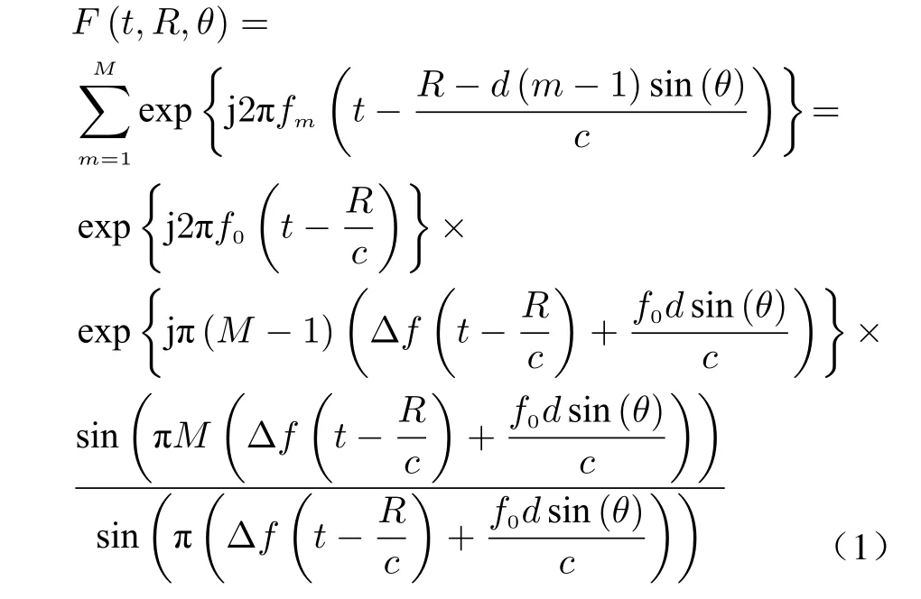
It is seen that the electric-field wave of FDA radar is different from that of the phased array radar. The beampattern depends on range, time and angle. The summarized property are provided in the following[60]:
1) At a fixed spatial distance R, the function relation of the beampattern with time and angle can be obtained. Its physical significance refers to the electric field distribution at different angles and different moments on the sphere with a spatial distance R. In other words, it is the electric field amplitude-phase response corresponding to the electromagnetic waves passing through the sphere of space. This is also the beampattern of the measured electric field of the FDA antenna usually obtained, which is more complex than the measurement of phased array antenna beampattern. The pattern of a phased array (PA) does not depend on distance, and certainly does not depend on time. The measurement of the FDA beampattern should be measured by using many synchronous probes in the spherical surface in anechoic chamber.
2) At a fixed time t, the function relationship of the beampattern with distance and angle can be obtained. Its physical significance is that the electric field intensity at different distance and angle positions in space at a certain instantaneous moment, which is difficult to measure. As time t changes, the spatial distribution of the electric field changes accordingly, just like waves on the sea.
3) At a fixed angle θ, the function relation of the beampattern with time and distance can be obtained. Its physical meaning is the electric field distribution of electromagnetic waves in this direction. This function is very important for radar echo signal processing. As is known to all,the beampattern of phased array (PA) is a function of angle, and the phase response of the signal envelope corresponding to different directions is exactly the same, that is, it has the characteristics of isotropy. Therefore, spatial beamforming and fast time matched filtering are independent and separable. However, under the FDA system, the amplitude response and phase response vary in any spatial direction, and the amplitude response and phase response are also different in different directions, which have the characteristics of anisotropy. Therefore, spatial beamforming and fast time matched filtering are often coupled together and inseparable.
The transmit beampattern of the FDA antenna can be understood as the automatic scanning of the signal main lobe over time in the spatial-angle dimension. Therefore, the energy in each spatial direction is the same. Due to this automatic scanning characteristic, the average power loss is M times that of the phased array and the equivalent antenna transmission gain loss is M times that of the phased array. In radar search mode, FDA can obtain the same processing gain as phased array through time accumulation. In this article, the correlation between the antenna emission pattern and the phased array, MIMO and FDA systems is given in Tab. 1.
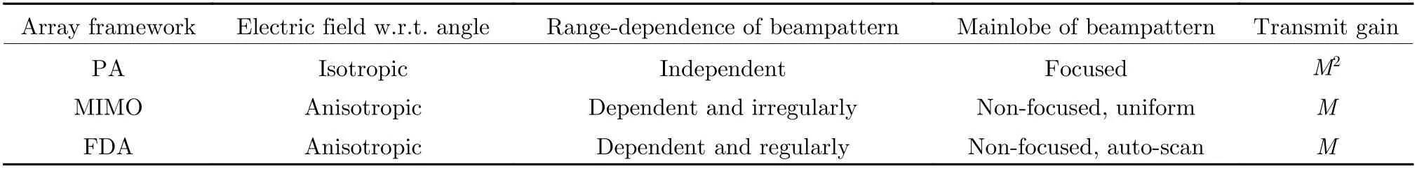
Tab. 1 Comparison of characters related to transmit beampatterns of PA, MIMO, and FDA[60]
Given a certain instantaneous time, the electric field distribution at different distances and angles in space can be obtained. With the change of time t, the electric field distribution will also change like a wave, and this change directly reflects the propagation characteristics of electromagnetic wave of FDA antenna. In order to demonstrate the propagation process of this electromagnetic wave, Fig. 1(a) is the radiation electric field distribution diagram of the phased array, Fig. 1(b) is the radiation electric field distribution of FDA under the conditions of Tp=1/Δf,Fig. 1(c) is the radiation electric field distribution of FDA under the conditions of Tp=1/(2Δf).It can be seen that the electromagnetic wave propagates in space with time, and the width of the range dimension corresponding to the effective electric field part is determined by the duration of the pulse. The electric field distribution on the range-angle is modulated by the transmit beampattern, at different instantaneous moments, the radiated electromagnetic wave propagates forward and reaches different positions. In addition, the main lobe of FDA transmit beampattern covering range of space angle is related to system parameters, when meet the Tp<1/Δf, the main lobe of the transmit beampattern covers only limited space angle. Therefore,by controlling the radar parameters, the space area covered by the FDA transmit beampattern can be controlled. At the same time, it should be noted that for the same angle but different distance space positions, although the time of electromagnetic wave passing through varies, the phase response generated by electromagnetic wave excitation is completely the same, independent of the array system.
The transmit beampattern of FDA radar varies with respect to range/time and angle,which is different from that in the conventional phased-array radar. Fig. 2 provides the propagation description of electromagnetic wave of FDA radar. Given an arbitrary far-field range, the electromagnetic wave will go through this range within the pulse duration Tp. The synthesized transmit signals in the far-field at rangesR1=cτ1and R2=cτ2can be respectively expressed as [60]

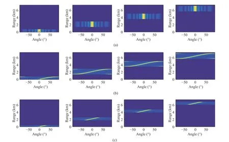
Fig. 1 Radiated power distribution and propagation of electric field: (a) PA; (b) FDA, Tp=1/Δf; (c) FDA, Tp=1/(2Δf)
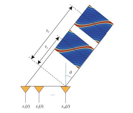
Fig. 2 Propagation property of synthesized transmit signal
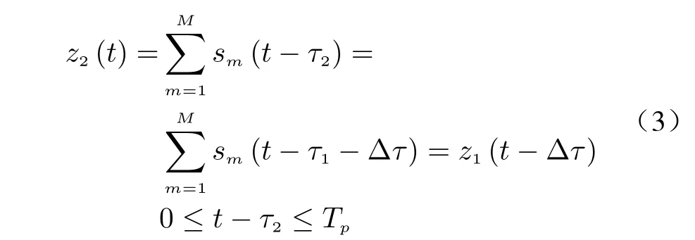
where τ2=τ1+Δτ. Notice that the range attenuation is ignored for simplicity. The synthesized transmit signal corresponding to τ2is a time-shifted signal corresponding to τ1. It means the synthesized transmit signal within the pulse duration (the pulse is moving forward at the light speed) remains unchanged during the propagation. This coincides with the classical theory of electromagnetic wave propagation. Note that the synthesized transmit signal is usually known as transmit beampattern. As seen in Fig. 1, the synthesized transmit signals of the FDA corresponding to the two time instances are exactly the same. The synthesized transmit signal will not stay or focus on some particular range-angle point during the transmission.
2.2 Receive Processing of Coherent FDA
Consider the process by which a signal transmitted by the FDA reaches a far-field target and then returned from the target to the receiving terminal. Considering the far-field narrow-band hypothesis, the signal is transmitted from M antennas to the target position of the far-field distance R and angle θ in space, and then backscattered to the receiving antenna. Without loss of generality, consider that the receiving terminal consists of N antenna units. When the same antenna unit is used for transmitting and receiving,there is N=M. Therefore, the signal form after receiving beam formation can be obtained at the receiving terminal [60].

The receive beampattern is [60]

The transmit beampattern is written as [60]
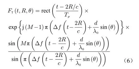
Under the system of impulse waveform,when the pulse duration meet the condition of Tp=1/Δf, transmitted beams can cover all angles of the beam. In this case, the power of FDA transmit beampattern is the same at all angles,and its transmit beampattern has the range-angle coupling characteristic. The amount of the FDA frequency step is far less than the bandwidth,and the dimension of distance beampattern of the cycle is c/(2Δf). It is much larger than the radar range resolution c/(2B), so the accuracy of the range parameter estimation based on FDA is limited.
Fig. 3 and Fig. 4 respectively show the results of the joint transmission-receive two-dimensional beamforming under different pulse durations, where both the signal synthesis at the FDA receiver and the conventional received beamforming are considered. Fig. 3 corresponding to the pulse duration of meet the requirements of the whole airspace coverage, namely Tp=1/Δf. The corresponding pulse duration in Fig. 4 can only meet the airspace covering[-30°,30°], namely the Tp=1/(2Δf). In this case,the transmitted signals are coherently superimposed in space, and each transmitted signal cannot be separated at the receiving terminal.Therefore, the degree of freedom controllable by the array is only that of the receiving degree of freedom. As can be seen from the simulation results in Fig.3 and Fig.4, FDA can complete the joint estimation of the distance and angle of the target in the receiving terminal. Although the accuracy of the range dimension estimation is limited, it also has certain reference value in some scenarios. Specifically, for the phased array with single-frequency pulse system, the range resolution is cTp/2. For each antenna unit firing single carrier frequency signal and the pulse width of Tp=1/Δf , since it has distance d direction, range resolution for c/(2MΔf)=cTp/(2M), is equal to the increased range resolution M times. In essence, because of the different unit antenna radiation signal frequency differences, equivalent system signal bandwidth for MΔf =M/Tp, compared to the single frequency pulse system of phased array is also increased M times. Of course, for impulse compression waveforms,where there is modulation within the pulse, such as phase-coded signals, linear frequency modulated signals, etc., the range resolution obtained by pulse compression may be much higher than the range resolution brought by FDA. In addition, it can be seen from the simulation results that the main lobes of the joint transmission-receiving beam formed point at different angles and different distances through the receiving beam formation pointing at different spatial directions.Therefore, the response of the processor in the coherent FDA 2-D beam domain has the ability to adjust the angle and distance in two dimensions, and has stronger anti-interference ability[20,44].
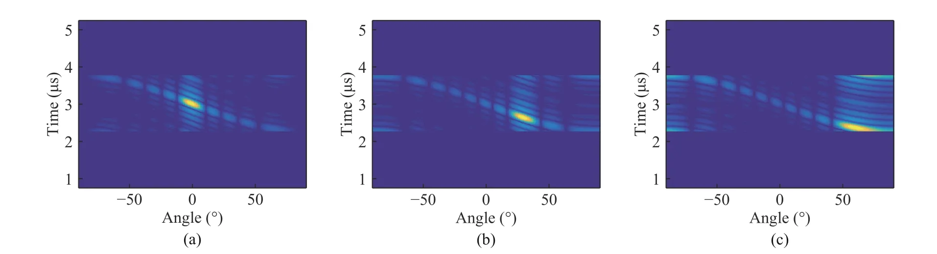
Fig. 3 Joint tranmit-receive beamforming with pulsed FDA, Tp=1/Δf:(a) θ0=0°; (b) θ0=30°; (c) θ0=60°

Fig. 4 Joint tranmit-receive beamforming with pulsed FDA, Tp=1/(2Δf): (a) θ0=0°; (b) θ0=30°; (c) θ0=60°
2.3 Future Works
The coherent FDA radar system has the capability of wide angle coverage, which is an effective way to realize wide coverage transmit and narrow beam receive, and can greatly improve the efficiency and capability of radar space surveillance in some application scenarios. We think the FDA study at least in the following aspects still need further work:
1) The receiving and processing technology of coherent FDA radar echo signal: considering the realization of equivalent transmission-receiving joint beamforming through receiving processing, for coherent FDA radar with modulation waveform within impulse, it is necessary to consider the two-dimensional matching receiving processing of fast time and angle.
2) Signal processing technology of coherent FDA radar in the receiver beam domain: consider how to receive multiple beams at the receiver terminal, obtain two-dimensional information of range and angle, improve the ability of signal processing and improve the accuracy of target parameter estimation;
3) Pulse accumulation of the coherent FDA radar and Doppler processing technology: different pulse arrays starting moment corresponding to the initial phase relationship may be changed,and will cause the antenna pattern between pulse and the pulse of change, which changes the direction of figure in the coherence between pulse, in this case, the coherent Doppler processing will become complicated, even can cause problems. In fact, when the design frequency step is an integer multiple of the pulse repetition frequency,the coherent FDA radar transmit beampattern satisfies the coherence between pulses.
4) Design technology of radar transmitter:including generation mode of frequency stepping signal, influence of initial phase of antenna unit,design of in-pulse waveform, coverage of spatial angle, spectrum of transmitted signal, etc.
3 FDA-MIMO Radar
3.1 Transmit and Receive Procedures
For simplification and without loss of generality,factors such as antenna element pattern and array error are ignored, and the transmit and receive array elements are assumed to be omnidirectional, isotropic and identical. For FDAMIMO radar, the transmitted signal of the m-th element can be expressed as [20]
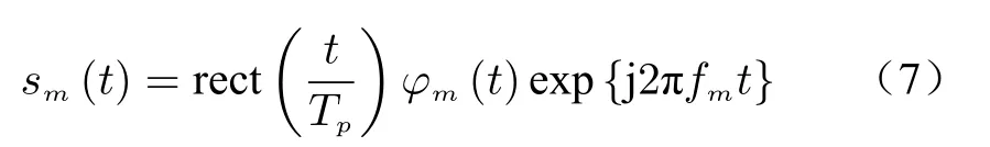
where φm(t) denotes the baseband modulation waveform. Usually in a radar system, the amplitude of the transmitted signal is constant, what can be adjusted is the phase and frequency of the baseband signal and the phase is the integral of frequency over time. The baseband waveforms of FDA-MIMO radar are assumed to be orthogonal theoretically. However, in practice, due to the waveform orthogonality needs to be valid under infinite time delay and the transmit waveforms are required to be orthogonal between each other,thus resulting in an overdetermined problem with only sub-optimal solutions [44]. In fact, the final power amplifier of radar transmitter usually works in the saturation state, thus the waveform design should satisfy the constraint of constant power, namely the constrained constant modulus.Moreover, the number of polyphase codes must be discrete and finite due to the existence of channel random error, the accuracy of system increases with the number of codes. Therefore,radar waveform design is an optimazition problem under finite constraints of radar system.
In practical applications, direct digital synthesis (DDS) technology is used for generating the frequency increment in FDA-MIMO radar,which has high frequency accuracy. From the perspective of FDA-MIMO radar implementation structure, including the transmitting and receiving structure, which are quite different from existing radar systems. Fig. 5 shows the transmit waveform design and implementation procedure of FDA-MIMO radar. The frequency increment signal is modulated with the baseband signal, it can be obtained after DDS processing with the high precision clock reference signal. After multiplying with the orthogonal transmit waveform, it is sent into the baseband analog channel and radiated from the antenna after conversion processing. Fig. 6 shows the receive procedure of FDA-MIMO radar corresponding to an arbitrary receive array element[17]. After down-converted and sampled, the received signals are processed by digital mixer (this module is unique and significant for FDA-MIMO radar receive procedure),orthogonal waveform matched filter, and then subsequent signal processing is carried out. Note that the digital mixing is processed in the full time domain.

Fig. 5 Transmit procedure of FDA-MIMO radar
After processed by mixing the reference carrier frequency, digital mixing of the frequency increment and matched filtering of the orthogonal waveform, the target signal model is expressed as[41,42] s=ξsb(R,θ)⊗a(θ) with b(R,θ) anda(θ)being the transmit and receive steering vectors,respectively. The primary difference between FDA-MIMO and traditional MIMO radar is the transmit steering vector of FDA-MIMO radar contains the range information of target, which is different from traditional range information determined by the time delay of echo signal. This range information provides radar with the ability to distinguish different targets in the transmit spatial domain, even though these targets may be located in the same range bin.

Fig. 6 Receive procedure of FDA-MIMO radar
3.2 Application and Advantage
In FDA-MIMO radar, by introducing a small frequency increment across the transmit elements and separating the transmitted waveforms with the matched filters, the joint angle and range information can be obtained. Moreover, the signals corresponding to different range ambiguity regions can be distinguished, improving the ability of clutter suppression and mainlobe deceptive jamming suppression in radar systems. Hence,the performance of FDA-MIMO radar w.r.t.parameter estimation, clutter suppression, and jamming suppression are analyzed in this subsection.
1) Unambiguous parameter estimation
Based on the above analysis, it is feasible for the FDA-MIMO radar to distinguish the range ambiguous targets, which provides a new approach to eliminate range ambiguity problem caused by high PRF system. Although different targets are overlapped in the time domain and only the unambiguous range of target can be measured, FDA-MIMO radar can effectively solve the problem of the index of range ambiguity estimation due to its transmit steering vector contains the true range of target. In [11], a joint range and angle estimation method based on FDA-MIMO radar is proposed. For example, we consider the case that one compressed white noise interference and four targets located in the normal direction of the antenna element at different range regions, these targets appear in the same range bin due to their true range are separated by a maximum unambiguous range in turn.Fig. 7 shows the spectrum distributions of the targets and the interference in the traditional MIMO radar and FDA-MIMO radar, respectively. It is seen that the spectrum distribution of the interference only depends on the spatial angle, its distribution in the transmit dimension is approximately white, and there is no difference between Fig. 7(a) and (b). However, the distributions of targets are different: since the four targets share the same angle, they are overlapped in the traditional MIMO radar. In contrast, ambiguous targets are separated in the FDA-MIMO radar due to its transmit steering vector is range dependent. The range ambiguity problem can be resolved by staggered PRF strategy in traditional radar system, while in FDA-MIMO radar, it can be resolved within only a single PRF.
2) Ambiguous clutter suppression

Fig. 7 Spectra distribution of barrage jamming and targets: (a) traditonal MIMO radar;(b) FDA-MIMO radar
When pulse DOFs is considered jointly,FDA-MIMO radar can introduce a three-dimensional DOFs of transmit, receive and pulse dimensions, which can make full use of the distribution characteristics of target, clutter and interference to address the bottlenecks in traditional MIMO radar and PA radar. The applications of FDA-MIMO radar on a moving platform (airborne, spaceborne etc.) in ground and sea clutter suppression and wide-area moving target detection are presented here, specific details are shown in [11-19]. Studies have shown that FDAMIMO radar provides additional controllable DOFs in range dimension and can distinguish echoes from different ambiguous range regions.Therefore, the clutter suppression and moving target detection in different ambiguous range regions can be processed in parallel and theoretically not affected by each other. This indicates that range ambiguity problem incurred by medium and high PRF can be alleviated effectively and no longer needs to adopt low PRF to avoid range ambiguity. Fig. 8 compares the spectra distribution in spatial and Doppler frequencies domains between the phased array radar and the FDA radar. As shown in Fig. 8, clutters in different ambiguous range regions are separated in FDA radar, which greatly differs from traditional phased array radar. Moreover, the radar has the ability to illuminate the entire observation space due to the adoption of orthogonal waveforms, and equivalent transmit beamforming can be done in the receiver to realize the detection of targets from different directions [19]. In conclusion, target detection in different ambiguous range regions and different spatial angles can be implemented efficiently using a parallel processing structure in the radar receiver. The scheme of multi-dimensional localized processing of FDA-MIMO radar corresponding to the moving target detection in the first ambiguous range region at the normal direction of antenna is presented in Fig. 9.
3) Mainlobe jamming suppression

Fig. 8 Clutter spectrum distribution in spatial and Doppler frequencies domains between the PA radar and FDA radar: (a) distribution in PA radar; (b) slice in the Doppler frequencies domain; (c) distribution in FDA radar; (d) slice in the Doppler frequencies domain
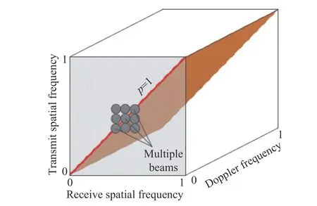
Fig. 9 Scheme of multi-dimensional localized processing
Another significant application of FDAMIMO radar is jamming suppression. Theoretically, since FDA-MIMO radar introduces additional DOFs in range dimension, it can suppress the mainlobe jamming which is difficult to tackle in traditional angular dimension adaptive processing. Shown in Fig. 10, since the mainlobe jammings share an identical angle with the desired target, traditional spatial adaptive processing technology suffers a severe performance degradation in the phased array radar. However,FDA-MIMO radar can utilize the difference between target and interference in the range dimension to deal with the suppression of mainlobe jammings. Studies have shown that FDAMIMO radar cannot address the mainlobe blanket jamming suppression problem due to the blanket jamming is independent of the transmit radar signal[41]. Furthermore, even for the mainlobe deceptive jamming suppression in FDAMIMO radar, a priori information of true target such as estimated target range and angle is required, and only jammings generated after delay larger than one pulse repetition time (PRT) can be suppressed. Because the transmit and receive spatial frequencies are identical, the true target is diagonally distributed in the joint transmit and receive spatial domain [41,44]. The distribution of false target in the joint transmit and receive spatial frequency domain differs from the true target since it has a time delay and thus received by different pulses. In [20], the problem of FDAMIMO radar mainlobe jamming suppression is initially discussed, however, the storage time of jamming signal is omitted here. In [43], the time delays and non-orthogonal waveforms were considered, and method to estimate the jammingpluse-noise covariance matrix was analyzed. Furthermore, the suppression performance degrades in the presence of transmit spatial frequency mismatch. To solve this problem, a robust method was proposed in [44] by placing artificial interferences with appropriate powers around the nulls of the equivalent transmit beampattern to suppress the jamming using the broadened notches.Notice that according to the additional time delays of the false target, the false targets belongs to two categories as shown in Fig. 11,where the false targets in region I are repeated very fast and located in the same receive pulse of radar with the true target. However, the false targets in region II are repeated with a relatively large time delay, these false targets are one or more pulses later than the true target. Actually,only the jamming in region II can be suppressed using the beamforming methods in FDA-MIMO radar. Further demonstration and analysis are needed for the suppression of fast repeater jamming.
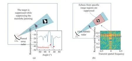
Fig. 10 Comparison of mainlobe deceptive jamming suppression between the PA radar and the FDA-MIMO radar: (a) PA radar; (b)FDA-MIMO radar
3.3 Future Works
For FDA-MIMO radar system, it provides extra controllable DOFs in range dimension which greatly enhances the flexibility in radar signal processing. The authors think that further research can be conducted in the following aspects.
1) Waveform design and optimization in FDA-MIMO radar: The waveform design objective is consistent with MIMO radar, but the corresponding optimization methods are different due to the existence of frequency increment.
2) System performance analysis of FDAMIMO radar: It is necessary to evaluate the system performance with consideration of transmit channel orthogonality, isolation degree, channel consistency, gain and phase error and other factors, and analyze feasible system indexes under certain application requirements.
3) Jamming suppression technique based on FDA-MIMO radar: It is feasible for the FDAMIMO radar to tackle the mainlobe jamming suppression problem which is a bottleneck problem in traditional radar system using its extra controllable DOFs in range dimension. Practical problems such as the pseudo-random distance distribution characteristic and the repeater jamming is coherent with the target signal should be considered simultaneously.
4) The application of solving range ambiguity based on FDA-MIMO radar: By exploiting the extra DOFs in the range dimension of FDAMIMO radar, it is expected to resolve the ambiguous target parameter estimation, range ambiguous clutter suppression, high-resolution wideswath synthetic aperture radar imaging and range Doppler multiple ambiguity problem mounted on a high speed moving platform, etc.
5) Multidimensional signal processing technology based on FDA-MIMO radar: Synthetical ultilization of FDA-MIMO radar’s DOFs in the range, angle, Doppler and polarization dimensions to carry out signal detection and recognition processing.
4 Conclusion Remarks
This paper overviews the state-of-the-art development of FDA techniques and applications. The concept of range/time-angle-dependent beampattern is summarized with emphasize on its propagation property in physical viewpoint. Two kinds of FDA frameworks, namely coherent FDA and FDA-MIMO, are presented. These two frameworks differ from each other in system design and signal processing algorithms. The specific concept of angle-dependent matched filtering is introduced for the coherent frequency diverse array radar. The receive structure and signal processing algorithms are introduced for the FDA-MIMO radar with analysis on its advantages in applications. Moreover, the possible research topics are discussed.
 Journal of Beijing Institute of Technology2021年1期
- Journal of Beijing Institute of Technology的其它文章
- MIMO Radar Waveform Design: An Overview
- Pattern Synthesis via Accurate Array Response Control: An Overview
- A Brief Introduction on Joint Radar and Communication Systems
- QoS-Aware Power Allocation Scheme for Relay Satellite Networks
- A New Transmit Beamforming Method for Multi-User Communication in Dual-Function Radar-Communication
- Dual-Use Signal Design for Radar and Communication via Joint Orthogonal Signal and Phase Modulation