Prospects of sea launches for Chinese cryogenic liquid-fueled medium-lift launch vehicles
Zhengyu SONG, Zhifeng XIE, Limin QIU, Dalin XIANG, Jinglin LI
a China Academy of Launch Vehicle Technology, Beijing 100076, China
b Beijing Institute of Astronautical Systems Engineering, Beijing 100076, China
c College of Energy Engineering, Zhejiang University, Hangzhou 310027, China
KEYWORDS Autonomous operations;Launch platform;Launch vehicles;Liquid hydrogen storage;Sea launches
Abstract This paper introduces the sea-launch technology of a cryogenic liquid-fueled medium-lift rocket.It first reviews the current state of sea launch technology,and then gives a brief introduction of China’s New Generation Medium-lift Launch Vehicle (NGMLV). The innovations in the NGMVL, such as responsive test and launch control, a H3 launch model, and unmanned operations, provide convenience for sea launches. Based on these innovations, this paper proposes a sea launch scheme,including the system configuration,test and launch processes,and an improved adaptive design for the rocket.Then,the launch platform is discussed in detail,which integrates the functions of sea transportation,assembly and test,as well as technical and launch areas.The layout and function divisions, fluid filling, gas supply and distribution systems, and lossless storage technology of LH2 are described in order. This breakthrough in sea launch technology will enable China to launch medium and large satellites and constellations ‘both on land and sea’, especially into low-inclination Low-Earth Orbits (LEOs), and it allows China to remain competitive in the fast-paced space industry.
1. Introduction
Sea launching has a long history. One example is the NASAItalian Space Commission program in the 1960s, where an equatorial launch site was located in the Formosa Bay in the Indian Ocean, which consisted of a fixed Launch Platform(LP) called San Marco.1-3Commercial sea launches began in 1995 with the multi-national cooperation Sea Launch project,4-6whose first launch in equatorial waters occurred in 1999.
Nowadays,sea launching refers to launch activities in a prescribed sea area, also known as offshore launching, such as that of China’s CZ-11 rocket.7,8Such LPs may be a converted oil-drilling rig,9or built as a self-propelled complex. The advantages of sea launches are: increased performance for achieving Geostationary Transfer Orbits (GTOs) and Geosynchronous Equatorial Orbits (GEOs), a flexible launch azimuth,fewer risks related to launching over populated areas,fewer conflicts with other launch systems or air traffic, and reduced damage arising from failures compared to the potential harm done to surrounding buildings, utilities, roads, etc.in ground-based launching. However, the cost-effectiveness of sea launches for Low-inclination Low Earth Orbits(LiLEOs) is still poorly understood.
In a Pareto-frontier analysis of regional coverage LEO constellations,10for target regions at 0°and 90°latitude,the optimal constellation inclination is 0° and 90°, respectively. For other latitudes, the optimal constellation inclination is slightly higher than the corresponding target latitude, and as the altitude of the constellation increases,the optimal inclination also increases. This is due to the long ground track and reduced revisit time of LiLEO compared to a Sun-Synchronous Orbit(SSO). In a research for Indian coastal regional coverage constellations, the optimal solution was an altitude of 814.5 km and an inclination of 16.5°;11in a regional fast revisit scenario for areas from 8°N to 22°N,multiple orbits whose inclinations range from 13.1°N to 22.1°N were proposed;12and it was shown that the lower the inclination, the fewer orbits needed for continuous regional coverage.13
Equatorial LEO (EqLEO) orbits have even lower inclinations,14which provide coverage of the majority of the South China Sea, maritime areas in South East Asia, most of the trade routes in the Indian Ocean, the southern Red Sea, and Gulf of Aden, and high revisit rates can enable nearperpetual surveillance.15,16The performance for achieving EqLEO drops dramatically if the rocket is launched from a site with a latitude larger than 10-15 deg. However, sea launches are adaptive to any orbital inclination, especially for LiLEOs and EqLEOs. They can also make up for the drawbacks of land-based launch sites in China, and solve the limitations of finding appropriate places where rocket jettisons can land on the ground without causing injury or damage to houses or people, and provide a new, safe, flexible, and economical way to enter into space.
However, sea launches face immense challenges. After many failures and a cascading series of delays,the Sea Launch Company became bankrupt and was eventually sold. Besides,the launch of a liquid hydrogen-fueled rocket is a very challenging task that has yet to be successfully achieved in the world.
The need for sea launches came from the world-wide commercial satellite launch plan during the 1990s. Due to the emerging needs of commercial launching at that time,a flexible launch mode, such as sea launches, was proposed. However,the needs of commercial launching changed shortly after,and only recently have we seen a greater surge in commercially launched satellites again. Chinese New generation rockets,whose combustion products are environmentally friendly,have laid a solid foundation for sea launching. The development of the shipbuilding industry in China is also growing rapidly.For example, the former Sea Launch’s mobile Odyssey LP was loaded onto the Hong Kong heavy load carrier Xin Guang Hua and transported from California to Russia in March,2020. However, China’s aerospace and shipbuilding industries have not yet conducted in-depth cooperation;hence,this paper is proposed to synergize these industries. With the development of responsive,autonomous launch control of NGMLVs,and the maturity of LH2 transportation, sea launching for a cryogenic liquid-fueled rocket,especially with LOX/LH2 engines,is becoming more predictable, practicable, and profitable.
2. Current situation of sea launch
2.1. Sea launch of liquid propellant rockets
The rocket Zenit-3SL has demonstrated its launch capability from sea,17which is a three-stage rocket using Liquid OXygen(LOX)/kerosene as the propellant. Its takeoff mass is about 470 tons,and its performance to achieve GTO is about 6 tons.In order to be compatible with sea launching, the structure of the rocket’s tail has been strengthened, and combined rocketto-ground connectors, which provide a combination of cryogenic fluids, pneumatics, and electrical service to the rocket,are widely adopted on Zenit rockets.
The launch infrastructure of Zenit-3SL includes a base port, an assembly and command ship, and a LP.4,6The payload-fairing assembly is mounted on encapsulated mechanical equipment and transferred horizontally by a payload vehicle from the payload processing facility to the assembly and command ship.18
The assembly and command ship serves as a complex for assembly and checks of the rocket. It consists of a shipboard control center for launch preparation and launching, provides a base for tracking during the ascending stage,and it contains cabins to house the crew and launch personnel.Before sailing,the rocket is moved out of the ship horizontally, lifted by cranes on the LP, and moved horizontally to the warehouse on the platform’s deck.
The LP has all the necessary systems for the installation of the integrated rocket into the launch position,filling with fuel,and launch operations.19As soon as the launch site is reached,pontoons plunge to depths of 21.5 m to achieve a steady launch position at which the horizontal position of the platform is provided with an accuracy of about one degree.
During launch,all personnel are evacuated to the assembly and command ship,which is about 5-8 km away from the LP.The launch control is executed from the ship through wireless links between the vessels.
The Sea Launch infrastructure is now owned by the S7 Group. In a report from Feb, 2nd, 2020, the Russian state space corporation Roscosmos declared it was ready to develop a new rocket,Soyuz-7,for sea launch,which would replace the Ukrainian Zenit rocket.20The new rocket is a sea version of the Soyuz-5 rocket that requires less fueling, but its performance will be almost the same as Soyuz-5,allowing it to carry up to 17 tons of payload to LEO,thanks to its launch location in the southern latitudes.
2.2. Autonomous operation and launch technology
Due to the limited space on a LP,launch operations should be mainly autonomous to minimize operational time and labor in ground processing while still maintaining reliability. Taking Zenit as an example, the pre-launch checkout and launch, as well as the reverse process for the rocket returning to the warehouse if the launch scrubs, are fully automatic; the mating,locking, and demating of the electrical and fluid connectors,are also automated.17The LP would be unmanned since the propellant-filling process.
It is even more difficult for autonomous Failure Detection,Isolation and Recovery (FDIR) for operations related to Liquid Hydrogen(LH2).NASA has conducted nearly 10 years of research in this field,including:(A)(2011-2014)the Integrated Ground Operation Demonstration Units project, which built the Simulated Propellant Loading System at the KSC Cryogenics Test Laboratory to study and verify its automated FDIR ability, aiming to improve the TRL (technology readiness level) of autonomous cryogenic fluid filling from 3 to 4.21,22(B) (2015-2017) The Autonomous Propellant Loading project,which adopted various cryogenic fluids,such as Liquid Nitrogen (LN2), liquid methane and LOX, to verify parallel filling, health monitoring, and FDIR, aiming to improve the TRL from 4 to 5.23(C) (2019-present) American Seed Fund- Ground Operation Autonomous Control Technology(ACT), released by NASA and planned for demonstration on prototype systems, aiming to improve the TRL to 6 or higher.24ACT supports troubleshooting, maintenance,upgrading and repair tasks, and it can automatically handle emergency and non-nominal conditions.It can also enable surface operations and maintenance on the Moon and Mars, so‘Autonomous, Real-Time Command and Control’ is still a key topic in NASA’s 2020 space technology ‘TX13: Ground,Test, and Surface Systems’,25and various forms of Artificial Intelligence (AI) technology are being introduced to deal with degraded system components or other forms of abnormal conditions.
2.3. Transportation and storage of liquid hydrogen
The stable, reliable, safe and economical supply of LH2 is another key factor for the sea launching of LH2-fueled rockets.Due to their complexity, high energy consumption and large occupation area, it is not preferable for hydrogen liquefaction to occur on offshore platforms. Instead, the hydrogen should be liquefied on land and stored in high-vacuum skid-mounted tanks with multi-layer insulation, which are installed on the LP.LH2 can be transformed from orthohydrogen and parahydrogen, and some measures should be taken to eliminate the direct emission of hydrogen,which can explode if GH2 is mixed with oxygen with a concentration higher than 4%.
The difficulties in the manufacture of LH2 storage tanks lie in the requirements of low evaporation rates,long vacuum life,and safe operation at LH2 temperatures. It has been reported that the United States, Russia, Japan and France all have experience in the production and use of large LH2 storage tanks,26such as the 3200 m3spherical tanks used in the US,which have a daily evaporation rate of only 0.03%; another example is the 540 m3tanks used by Kawasaki Heavy Industries in Japan, which have a daily evaporation rate of 0.18%.In China,some horizontal LH2 storage tank have been built,26such as the 80 m3LH2 storage tanks made by a cooperation between the Sichuan Air Separation Plant (Group) Co. Ltd.and the Beijing Institute of Space Test Technology,which have a measured daily evaporation rate of about 0.97%; others include the 300 m3tanks made by the CIMC Sanctum Cryogenic Equipment Co. Ltd, and the 330 m3tanks made by the Nanjing Chenguang Group.
Transportation of LH2 by ship is an effective way to distribute hydrogen energy throughout the world. In the hydrogen energy development plan jointly drafted by Canada and Europe in the 1990s, it was proposed to ship LH2 from Canada to Europe with a volume of 15,000 m3.27Japan also conducted shipping LH2 tests in February, 2017.28Kawasaki Heavy Industries, which also provide LH2 storage tanks for the Japanese H-II rocket, announced that the world’s first LH2 ship was officially namedSuiso Frontierand launched in December, 2019.29The two tanks’ volumes on the ship totaled 1250 m3, which consisted of a stainless steel vacuum thermal insulation double hull, a special dome structure for maintaining vacuum conditions, and a glass-fiber reinforced polymer insulation supporting structure.30-32The ship is planned to sail 9000 km from Australia to Kobe, Japan, but late 2020.
The long-term storage of LH2 can be realized by passive or active insulation.33Active methods are better but more complicated due to the need for an external energy supply, and they can achieve zero boil off(ZBO).ZBO technology was first proposed by NASA at the end of the 20th century due to the need for long-term orbit storage of cryogenic propellant required for Mars exploration.34In 2017, NASA completed an integrated refrigeration and storage test of a large-scale LH2 tank on the ground.35,36However,whether it is worth attempting to find ways to reduce the daily evaporation rate of LH2 at the expense of increasing investment and complexity,is still under discussion.
2.4. Thoughts on sea launches of Chinese liquid-propellant rockets
Technological breakthroughs did not bring commercial success for the Sea Launch Company. In a report made by the US Air Force, which compared Sea Launch technology with current US military launch operations, three factors including launch cost, reliability, and responsiveness were addressed.37Unfortunately,the Sea Launch Company did not perform well relating to the latter two factors, which were attributed to its eventual demise.
The biggest advantages of cryogenic liquid-fueled engines are their higher specific impulse and eco-friendly combustion products. However, challenges lie in the complexity of ground operations, involving filling, gas replacement, charging or venting, pre-cooling, gas blowing or sealing, heat exchanging or temperature regulation, vacuumizing, etc., and the risks of rapid deterioration in case of failures, let alone the notorious difficulty in storing LH2. Promisingly, attempts to develop air launching with hydrogen/oxygen engines are very active,38where even an air-launched large rocket has been proposed.39Compared with these requirements, sea launching has more relaxed constraints,and provides a seamless connection to reusable launcher recovery at sea.
Based on experiences and challenges of sea launches,a reliable, responsive rocket has the potential for shipboard operations.It should,however,meet the needs of large payloads,or multiple constellation satellites sharing one flight, which can lower the launch cost per kilogram.
3. Candidate rocket
The vertical assembly plants, huge mobile launch pad, and grand serving towers that are usually applied in groundbased launches occupy a lot of space, and they cannot be placed for sea launches, where the shipboard space is limited.Therefore, among the new generation of Chinese rockets,40,41in this work we focus on CZ-8/RH.
The CZ-8 rocket mainly provides launch services for SSOs.The core booster has a diameter of 3.35 m equipped with two YF100 LOX/kerosene engines. The two side boosters each have a diameter of 2.25 m, and both are equipped with a YF100 engine. The second core or upper stage has a diameter of 3 m, equipped with two YF75 LOX/LH2 engines. The rocket without side boosters is named CZ-8A. Each rocket provides two configurations, noted as CZ-8/ZH and CZ-8/RH, where ‘ZH’ denotes the combination of stages inherited from CZ-7 and CZ-3A,while‘RH’denotes the innovative version of a low-cost, highly reliable and easy-to-use vehicle,revised for commercial market, which is preferable for sea launches.
The innovations of CZ-8/RH, such as integrated onboard avionics, responsive launch control, unmanned operations,smart aerostructure manufacturing, etc., provide feasibility for sea launching.Its service cycle of 7-10 days,and the annual production of 20 rockets by the Chinese Academy of Launch Vehicle Technology, CALT, makes it competitive in the fastpaced commercial launch market.
3.1. Performance evaluation
Launching at sea has the obvious advantage of performance for low-inclination missions.The inclination of the target orbit usually cannot be less than the latitude of the launch site.Otherwise, it would launch the satellite into a transfer orbit,then trigger the upper stage many times to reduce the inclination and increase the perigee height for orbit circularization.For example, the performance of CZ-8 for GTO (0° inclination) missions in Wenchang is only 0.75 tons due to yaw maneuvers, but this quadruples to 3.05 tons if the rocket is launched in equatorial waters.
The latitudes of some launch sites are listed in Table 1.Fig. 1 gives a comparison of the performance to achieve LiLEO for CZ-8 launched from Wenchang and at sea.
3.2. Distinguishing features
(1) Responsive test and launch control
In recent years, some responsiveness improvements have been made to the Long March rockets, such as a horizontal assembly-and-transfer mode for LOX-fueled small rockets and instantaneous window launch control for the LH2-fueled stage.42,43However, the size of the control center, the system-divided test and launch control facilities, and the mostly human-in-the-loop working mode, cannot meet the requirements of ‘ship and launch’ in the commercial launch market. Only a systematic optimization derived from scratch,rather than applying local updates to existing rules or devices,can really meet the needs of new generation medium-lift rockets. Therefore, a universal six-tier abstract model is proposed here for the planning of CZ-8/RH Test and Launch Control(T&LC) system, as shown in Fig. 2. All functions of T&LC sub-systems have been mapped into two integrated, modularized and configurable cabinets. They are portable for onsite installation,and only one controller terminal and one operator are retained for operations. The pre-launch check, command,and control are automated once the software is started. More details about these can refer to the literature.44
(2) Horizontal assembly-test-transfer mode
The test and launch mode are widely discussed for every new rocket, and each type of mode has its own applicable scenarios;45-47see Table 2 for a comparison of different modes.Among them, the horizontal assembly-test-transfer mode,referred to as the H3mode for short, is commonly regarded as the most economical.For example,ESA changed the vertical mode of Ariane 5 to an H3mode in its newly developed rocket Ariane 6,and this change was regarded as the most influential trade-off, especially in terms of cost effectiveness, for Ariane launchers,although its side solid-fueled boosters have been vertically integrated with the core stages in the launch area.48For CZ-8/RH,both the boosters and upper stage are assembled and transported horizontally. It should be pointed out that not all satellites are suitable for horizontal assembly, which instead are vertically assembled for land launches.
To accommodate the H3mode, onboard electronic products, pyros and explosive devices, and engines are all installed on the stages for transportation,and the pyros are required to be insensitive (rather than sensitive).
An erecting bracket is installed on the transfer truck,which supports the rocket. In the launch area, the bracket is mated and locked with the erecting device, and this assembly raises the rocket by the driving of oil cylinders. The rocket sits on a launch pad, and is locked by windproof pull rods. A simple diagram of the horizontal transfer and erecting infrastructure is shown in Fig. 3.
To reduce maintenance costs,the launch pad is designed as a fixed one. The operations before launch, and the personnel accesses to the service tower,are greatly reduced.The adaptive initial alignment method replaces the previous ground aiming facilities,and roll control shortly after liftoff is applied to align the required launch azimuths.
(3) Unmanned operation since cryogenic fluid flowing
The following measures are taken:
(A) Automatic remote control. Large flow, remotecontrolled pressure regulating valves are adopted. The closed-loop control of the pressure regulation replaces the manual adjustment and monitoring before launch.
(B) Adopting T-0 connectors. The LOX loading and vent connectors of the core and side boosters are adjusted to the tail of the rocket, and they demate automatically when the rocket takes off. The filling and discharging connectors of the upper stage (LOX/LH2), and the GH2 vent connector, are relocated to the side fronting to the erecting device, and upgraded to T-0 connectors.
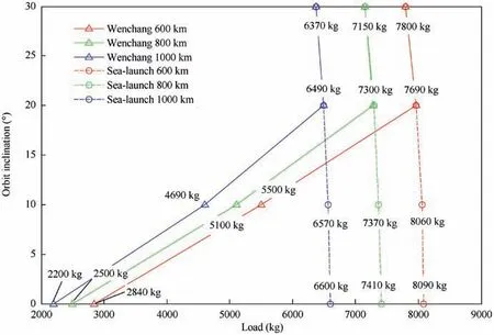
Fig. 1 Performance assessment for LiLEO orbits for CZ-8 launched form Wenchang and at sea.
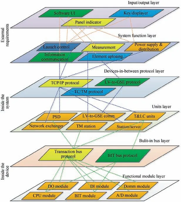
Fig. 2 Six-tier model of the T&LC system.
(C) Reducing the number of ground-to-vehicle connectors,by the concerted gas supply and distribution for all stages, and self-gas seals. Besides, the ground-tovehicle interfaces are integrated into combined connectors.
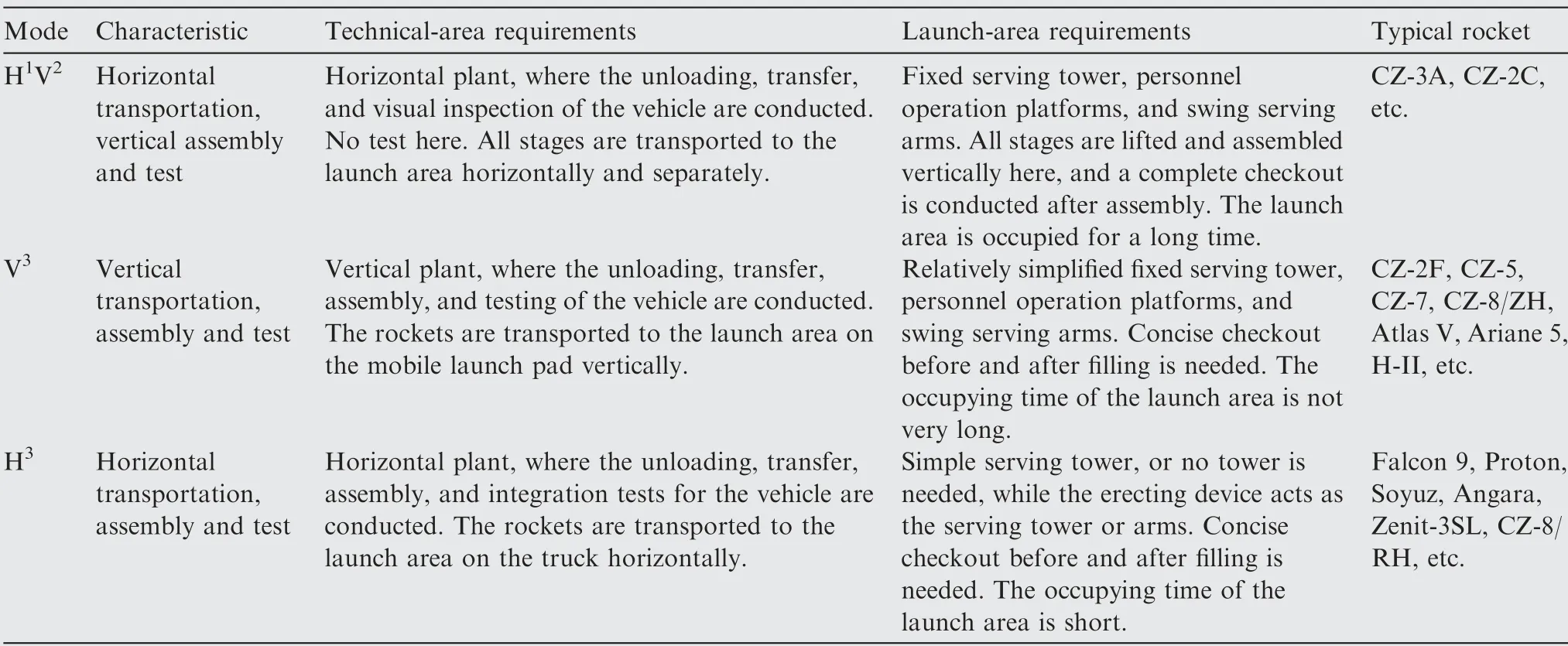
Table 2 Comparison of different launch modes.

Fig. 3 Horizontal transfer and erecting infrastructures.
4. Sea launch system
4.1. General description
(1) Sea-launch system
The sea launch system includes a harbor base,a Command and Control Ship (CCS), and a LP. An Assembly and Test Plant(ATP)is on the LP’s deck,which also acts as the technical area. On the opposite side to the ATP is the launch area.The CCS serves as command and control center,and a telemetry base for the ascending phase. The vehicle storage plants,Payload Checkout Workshop (PCW), are located on the harbor base.
(2) Horizontal operation mode
Only the H3launch mode can simplify launch infrastructures. The rocket is assembled and tested at the ATP, which is then transferred to the launch area and raised by an erecting device. The workforce then evacuates to the CCS, which sails 5-7 km away from the LP. Wireless control (such as 4G or ultra-short wave)is used for the pre-launch checks,fuel filling,and ignition. When the engines start up, the erecting device tilts up and all connectors are released.
If the rocket is on hold due to failures, a reverse process is activated to discharge the cryogenic propellant through T-0 connectors. When safety is guaranteed, the workforce is allowed to address any failures on the LP. If the failures are isolated onboard the rocket, the erecting device will clasp the rocket and pull it backward to the horizontal state and return it to the ATP.All these activities are automatically conducted,or with minimal manual interferences.
(3) Adaptive enhancements of the rocket
All stages are assembled and tested before being shipped to the harbor base, while the activities left on the LP are greatly minimized. The enhancements made to the CZ-8/RH rocket are discussed in more detail later.
(4) Launch platform
The offshore LP has the functions of a transport ship, a horizontal assembly plant, and technical and launch areas.For more detailed discussion, see Section 5.
(5) Launch pad
The launch pad includes upper and lower parts. The upper part is docked with the rocket in the horizontal state,where all the ground-to-vehicle connectors are mated,including the connections between the tail of the rocket and the upper part,and those between the upper stage and erecting devices. When the rocket is raised in the launch area, only the ground-to-ground connectors between the upper and lower parts are mated vertically after the two parts are locked.
The connectors of the lower part to other ground facilities are connected in the launch area and checked in advance before the rocket is transferred to the launch area, so as to effectively shorten the pre-launch operation time and the launch cycle.
4.2. Work flow
The objective of ‘ship and launch’ is to cope with the capricious weather conditions at sea; therefore, all activities shipboard should be optimized. The work flow is shown in Fig. 4, which consists of the following steps:
(1) The core and side boosters, upper stage, and the fairing are transported to the harbor base by land vehicles,then lift to the LP and shifted to the ATP one-by-one.
(2) The payload is tested and filled in the PCW,then encapsulated and lifted to the LP’s deck and shifted to the ATP, where it is mated with the fairing.
(3) All stages, payload/fairing assembly, and upper launch pad are assembled horizontally, tested, and then shifted to the launch area for a launch rehearsal with no propellant filled. After that, the rocket is restored to the horizontal state, and then shifted to the ATP as a whole.
(4) When the connectors between the upper launch pad and the rocket are mated, functional checks on the rocket and payload are planned during the voyage to the launch site, including inspecting the air tightness of and gas replacements for the rocket’s tanks. After that,a certain positive pressure gas is stored in the tanks.
(5) When reaching the launch site, the system-level checks and launch processes are conducted,including the blowing out, air tightness inspection and gas replacement of the ground serving pipeline. The positive pressure gas inside the tanks could blow out the fuel-filling pipelines of the ground support system if there is air in them due to seal leakages.
(6) The rocket(with the upper launch pad)is transported on an automated driving rack truck along a railway laid between the ATP and the launch area. The rack truck joins in with the erecting device,and the rocket is raised,sits atop the launch pad, and locked, whereby the truck returns to the ATP. All operations are performed unmanned.
(7) After the connectors between upper and lower parts of the launch pad are mated, the pre-filling checkout, fuel filling, and post-filling checkout are executed in order.Then, the rocket is ready to launch.
All the operations in the harbor base and those in the horizontal ATP, are controlled through the control room on the LP, but the command and data are relayed to the CCS. For the operations after arriving at the launch point, they are remotely controlled from the CCS.
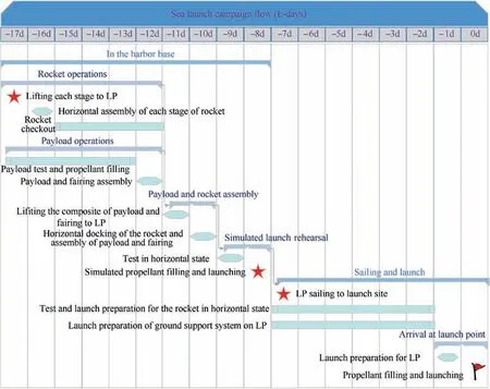
Fig. 4 Sea launch campaign flowchart.
4.3. Adaptability to the sea launching
4.3.1. T-0 connectors and umbilicals
The T-0 connectors provide service through launch up to and including lift-off (T-0). They are installed on structures called umbilicals, which automatically retract at liftoff, thereby demating the connectors.
The ground umbilical systems provide services that include, but are not limited to, electrical power and control,propellant loading and venting, pneumatic system supply,hazard gas detection and purging, as well as systems checkout capabilities.
For cryogenic rockets, the LH2 vaporizes rapidly if the launch is postponed for a long time, resulting in a sudden increase of tank pressure. At this time, either discharge the LH2 or relieve the pressure by opening the GH2 vent valve,otherwise the tank will break up or even explode. If the connectors are disengaged,it is very risky to reconnect them manually.Moreover,due to the shaking of the rocket arising from wind and waves at sea, as well as condensed ice that forms from air moisture that covers the mating surface,it can be very hard to achieve self-alignment and automatic mating. Therefore, keeping the connectors mated until takeoff is a safe choice.
NASA has always valued technologies such as quick demating and remating T-0 couplers, automated umbilicals,self-cleaning or anti-icing cryogenic couplers,as demonstrated by their continued use in current 2020 NASA space technology.25NASA launched their automated ground umbilical system project many years ago, and they accumulated vast amounts of experience in the use of T-0 umbilicals during the era of the space shuttle.49,50Many umbilical types, such as tilt up,swing arm,hose drape,drop arm,Tail Service Masts(TSM), etc., have been developed. The T-0 umbilical system was also an important component of the Ares rocket,51and there are at least nine umbilicals used in the Space Launch System (SLS).52,53
For Long March rockets fueled with conventional propellant, the ground-to-vehicle connectors usually demate prior to launch. T-0 connectors have gained more attention with the application of cryogenic propellants.54In China’s NGMLVs, all electrical vehicle-to-ground interfaces, and gas and cryogenic propellant interfaces on the boosters, are concentrated in the tail of the rocket, which are unplugged after liftoff. The ground cryogenic propellant filling and venting connectors are protected by the TSM, which is a counterbalanced structure that is hydraulically operated and pneumatically/electrically controlled, which automatically closes the upper sliding cover after the rocket takes off to a certain height, thereby avoiding ignition of the residual propellant in the pipeline.55
For the second stage,tilt up or service masts umbilicals suit connectors which are attached to the side wall, while hose drapes are used for air-conditioning connectors. When the rocket takes off,the erecting device tilts back at a small angle,which causes the umbilicals to retract and detach the connectors and limit their rebound. One of the most critical features of all T-0 systems is their ability to disconnect safely,under all conditions. This requires backup systems. For example, the side wall connectors can be detached through pulling the locking mechanism, or activating a lanyard to provide additional force to break the weakening groove of the ball joint if the unlocking mechanism is jammed.56
4.3.2. Launching on a moving base under wave fluctuations
The Inertial Measurement Unit (IMU) should determine the initial attitude matrix when involved in the navigation, which is called initial alignment. Taking the precise information of the main Inertial Navigation System (INS), such as the shipboard INS, as a reference, the error between the sub INS,i.e.,the rocket’s onboard IMU,and the main INS is estimated by a Kalman filter; these methods are called transfer alignment.57,58By matching the speed, angular velocity, attitude,acceleration, or the combinations of the above state variables,many types of filters have been designed,which are widely used in ships, warcraft, aircraft, etc.59,60Then, the azimuth of the rocket is determined by the self north-seeking algorithm based on the IMU.
For sea launches, wave heights up to 2.5 m are common.Compared with land launches, some active control methods should be considered.During pre-launch operations, the inclination of the LP due to wind, waves, the movement of the transfer truck, and operations atop the LP, will increase the load on the clamping part of the rocket to the launch pad interfaces. To strengthen this part requires an increase of the rocket’s weight. So, a stable platform between the LP and rocket was proposed to isolate the impact of ship sway on the rocket and liftoff.61However, the clearance to the rocket from the tiling erecting assembly back changes with the LP’s sway,and it is not so spacious to avoid collision during liftoff.Another proposal is to develop a shipboard horizontal control system,such as the‘trim-and-heel’system used on the Odyssey LP,which controls pumps that distribute water among the pillars to level the LP.62
If the launch-support equipment is confined near the LP,an onboard exhaust trace control may also be needed,which swivels the engines during liftoff to avoid their blast damaging the facilities.63,64
4.3.3. Other updates
(1) Complete unmanned processing for fuel filling
The kerosene interface located on the tail-side wall requires manual disconnection after servicing.This should be converted to a fully automated system, including withdrawal of the pipelines, so the whole filling process is unmanned, automatic and remotely supervised.
Countermeasures have been made for typical failures in CZ-8/RH, designed as a knowledge base.44These measures activate automatically to reconstruct the system if a failure occurs and the failure mode is matched. However, current knowledge bases are unable to cope with an unpredicted abnormal situation, so a human-on-the-loop mode is still required. Fully autonomous operations need to be further studied to deal with emergent or off-nominal situations, as demonstrated by NASA’s ACT which funds research in this area.
(2) Improving the automation level
The level of automated rocket assembly, transportation,erecting and other processes, including withdrawal of the windproof pull rod, needs to be improved.
(3) Improving the test efficiency
The launching work flow should be optimized within 12 h.This could be responsive to the fast-changing sea conditions,and relax the requirements for LP stability.
(4) Environmental adaptive design
The onboard electronic components and structural parts should work well under the conditions of high salt fog,temperature and humidity. The diversion effect of high-temperature and high-speed combustion gas emitted by engines is different from that of land launches,so the influences of the open stream diversion channel to the rocket and LP also need to be studied.
5. Sea launch platform
In China, most studies regarding offshore LPs are focused on small rockets, such as the catamaran proposal.65,66Considering hydrodynamic performance, the semi-submersible selfpropelled platform is more preferable for medium and large rockets.67The design of LP is beyond the scope of this article,as we mainly study the functions it should have to meet our launch needs.The LP’s preliminary requirements and configurations can refer to Appendix A.
5.1. Scheme and layout
The sea LP is self-propelled, and can partially submerge by pouring seawater into the pile legs to ensure stability during the launch. The ATP, launch pad, and gas, electricity and hydraulic facilities, are installed on the deck. The rooms on the deck for command, test facilities, power supply and distribution, air conditioning system, and gas supply system can be shared for activities in the technical and launch areas.
The functional areas mainly include:
(1) ATP,also known as the technical area.Satellite parking and mating with the fairing, horizontal integration of boosters, upper stage, and satellite/fairing assembly,mating of ground-to-vehicle T-0 connectors, check for the avionics, propulsion, pressurizing, and propellant transmission system,and tank gas replacement, are executed here.
(2) Erecting operation area, located between the ATP and launch area, where the rocket is transported through and raised, and standard rails are laid with a length of about 70 m.The boosters,upper stage,fairing,and payload are also hoisted from land to this area by the crane on the LP, put on the railcar, and relayed to the ATP one-by-one for assembly.
(3) Propellant warehouses, which include kerosene, LH2,LN2, and LOX warehouses, and filling control equipment. The LOX and LH2 warehouses are arranged separately on each side of the platform, respectively,both in the open air on the deck.The kerosene warehouse is located under the deck for better temperature regulation.
(4) Gas cylinder warehouses,which support the activities in the technical and launch area. Nitrogen is produced by the vaporization of LN2, and stored temporary in the high-pressure cylinders to meet the demand of the online supply. Helium is supplied directly by high-pressure cylinders.
(5) Power generators,supply and distribution facilities.For the equipment involved in the ignition and launch process, some Uninterruptible Power Supplies (UPSs) are provided.
(6) Test equipment, including measurement modules, controllers, communication devices, etc.
(7) Test and launch control rooms, or the control centers for the shipboard operations, where all data are collected, distributed, and analyzed. When fuel filling starts, their functions shift to the CCS.
(8) Launch area, which is on the opposite side to the ATP and at the edge of the LP. The erecting device, launch pad,stream diversion channel,noise reduction facilities,etc., are located here. The tail flame at take-off passes through the stream diversion channel, so the force does not act vertically on the platform,and thus imposes little impact on the stability of the rocket and the LP. Noise reduction is done by spraying water to reduce the vibration environment during take-off, cooling the launch pad and LP as well.
(9) Living and logistics support area,whose service capacity is about 40 people.
(10) Heliport,which is used to commute between the LP and CCS.
5.2. Fluid filling systems
The cryogenic fluid filling systems include LH2,LOX and LN2 filling systems. The LN2 filling system is used to regulate the temperature of the LOX and kerosene, and cool the helium.The system composition is shown in Fig. 5 and described in the following:
(1) The LH2 filling system adopts self-pressurizing and extrusion method, and is equipped with two multilayer vacuum insulated storage tanks. The vented GH2 could be transferred to a high-altitude flare stack.
(2) The LOX filling system adopts the external pressurizing and extrusion method,and the super cooled LOX filling is guaranteed by the LN2 cryocooler.
(3) The LN2 filling system adopts the self-pressurizing and extrusion method, which is placed in the same warehouse with the LOX filling system.
The filling process is remotely carried out by the automatic control system, which has the abilities of filling the multiple tanks simultaneously, fuel supplement, and discharging under the reverse process, etc.
Kerosene, opposed to the cryogenic propellant, is a conventional fuel stored at room temperature,which has stable chemical properties and is loaded by open-type pump pressurization. It should have the ability to fill all onboard kerosene tanks concurrently at a large flow, corresponding to 3000-5000 L/min for each tank.
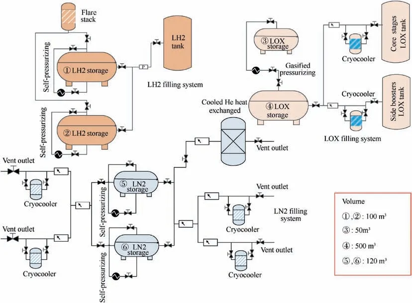
Fig. 5 Diagram of the fluid filling systems.
5.3. Gas supply system
(1) Nitrogen supply system
It is used for pipeline blowing, tank replacement and pressurization, gas-cylinder charging, anti-condensation blowing,gas seal blowing, etc.
(2) Helium supply system
It’s used for the LOX/LH2 upper stage, including blowing off the solenoid valve,gas replacement and pressurizing for the tank,onboard gas cylinder filling,pipeline blowing off and gas sealing, etc. The requirement for normal launch plus propellant vent treatment should all be considered.
Due to the scarcity of helium sources, some measures should be devised in the future, such as self-pressurizing of the LH2 tank, replacing control and purging gas by nitrogen partially, etc. Then the consumption of helium for one launch mission (without considering propellant venting) can be reduced to about 5000 standard cubic meters.
(3) Low-pressure air support system
The low-pressure air support system is mainly for the environmental protection in the ATP and within the fairing. The air conditioning system should have desalting and dehumidification abilities.
5.4. Lossless liquid-hydrogen storage
The evaporation of LH2 in the period of storage and transportation is inevitable.According to the research of LNG(liquefied natural gas)tankers,when exposed to external wind and waves, the sloshing of the ship cabins will cause more intense rolling and increased evaporation of LNG, and the evaporation rate during sea transportation is higher than that during ground transportation by more than 10%.68The latent heat produced by LH2 vaporization is much smaller than that of LNG,and the temperature is also lower;hence the daily evaporation rate of LH2 is greater than that of LNG during sea transportation.The passive technology represented by thermal insulation structure is unlikely to fundamentally solve problems such as evaporation losses, overpressure vents and temperature rises. Therefore, long-distance sea transportation needs new innovations to address these problems.
Due to the sway of the ship,the LH2 tank is required to have sufficient strength and the ability to restrain any unstable thermodynamic phenomena caused by the rolling of the cryogenic liquid. At present, there is no mature marine skid-mounted large volume LH2 tank at use in China.The best apparent thermal conductivity of multilayer thermal insulation materials produced in China is 7.0×10⁻⁵W/m·K(300-77 K),while the best performance in the world is <1.0×10⁻⁵W/m·K (300-77 K).The daily evaporation rate in China is about 0.23%,and these tanks are horizontal or vertical, as large LH2 spherical tanks have not yet been realized.26,69Key technologies, such as high vacuum multi-layer insulation technology, ultra-low apparent thermal conductivity multi-layer insulation materials, large diameter sandwich pipeline adaptive compensation, spherical tank structure design and so on,need to be developed.
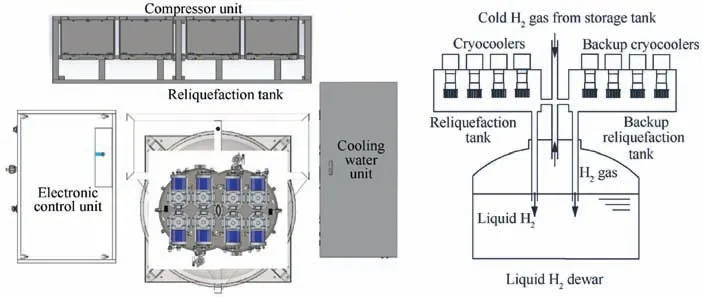
Fig. 6 Diagram of a lossless LH2 storage system.
The approach of lossless storage technology based on cryogenic refrigerator is currently under investigation for longdistance LH2 transportation by sea. It is composed of a reliquefaction tank, compressor units, water chillers, and electric control units, as shown in the layout in Fig. 6.
The evaporated hydrogen in the LH2 tank is delivered to the reliquefaction tank through a vacuum transmission pipeline, where heat is removed by the heat exchanger cold heads of the cryocoolers. Then the liquid hydrogen can be retrieved after condensation and liquefaction. Three key technologies include: (A) A high-performance regenerative cryocooler,which should be adapted to the working conditions of the ship,and provide a stable supply of the coolant for GH2 reliquefaction under the temperature zone of liquid hydrogen (~20 K).(B)The integrated design of the cryocooler and cryogenic container to realize the effective transmission of the cooling capacity and the precise control in the reliquefaction process. (C)High-efficiency hydrogen liquefaction heat exchange technology with the integrated design of condensation and orthohydrogen/parahydrogen conversion, so all the processes can be completed within a compact space.
6. Conclusions
In this paper, the sea launch technology of a cryogenic liquidfueled launch vehicle was discussed. More studies, such as the safety control of the launch site,the surroundings,and the falling area of the jettisoned parts, are required, along with the further development of the project.
Sea launch technology is an innovative launch mode in China, which has not been demonstrated for LH2-fueled rocket elsewhere in the world. With maturation of LH2 transportation and long-term storage technology,the feasibility and commercial value of launching cryogenic liquid-fueled rocket at sea is gradually increasing.
The background of Chinese NGMLV is introduced, which adopts the ideals of a cost-effective oriented reliability design,and its progress in H3launch mode and unmanned operations,etc.,has paved the way for future sea launches.Then the paper proposes a blueprint for the sea launch system, and the LP is subsequently discussed in detail.
Our analysis showed that the NGMLV can meet the needs of sea launching after some improvements. The proposal presented here is a good starting point as an early study of the applications of sea launching.It is also economical as it adopts an integrated approach that includes the LP, transfer ship,assembly and testing workshops,and the technical and launch areas into a single complex.This proposal promotes the fusion and development of related technologies,and enables China to launch medium and large satellites and constellations‘both on land and sea’, bringing a competitive prospect in the flourishing space industry.
Declaration of Competing Interest
The authors declare that they have no known competing financial interests or personal relationships that could have appeared to influence the work reported in this paper.
Acknowledgements
This study was supported by the Research on Design Technology of Sea Launch and Recovery Platform (Ship), one High Tech Research Project of MIIT, China.
Appendix A.Preliminary requirements for the launch platform
The preliminary functional area configuration is shown in Fig. A1. The basic performances are listed in Table A1.
●Facilities on the launch platform mainly include:
(1) Ground support equipment and systems for prelaunch processing and launch:
■ATP, fairing closure plant
■Transport truck, erecting bracket, and erecting device
■Launch pad
■Hoist
■Oxidizer and fuel filling systems, including:
o LH2 Tank, (100 m3)×2 (lossless system)
o LOX Tank, 50 m3and 500 m3
o LN2 Tank, (120m3)×2
o Kerosene Tank
■Helium supply system (see Table A2), nitrogen supply system (see Table A3), air supply system
■Power generators and supply system
(2) Complex of automated processing control systems
(3) Launch measurement complex
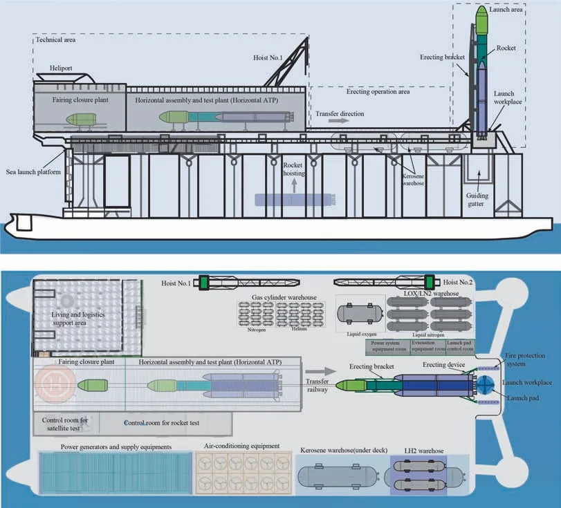
Fig A1 Layout of the sea-launch platform.
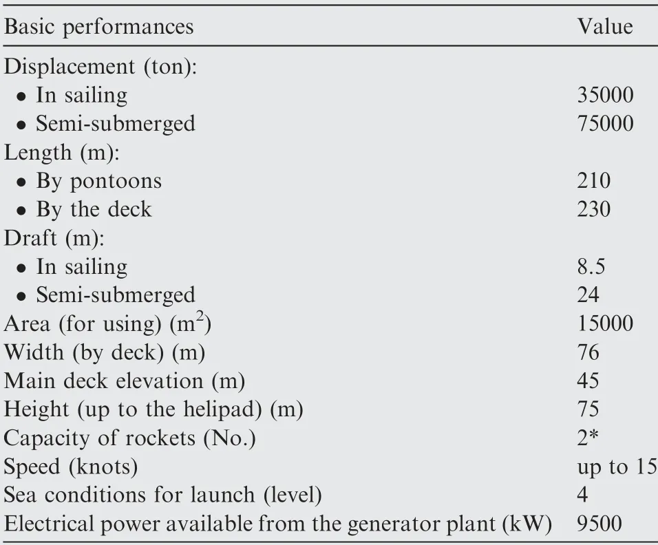
Table A1 Basic performances of the LP.

Table A2 Helium supply system.
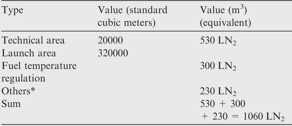
Table A3 Nitrogen supply system (standard cubic meters).
 CHINESE JOURNAL OF AERONAUTICS2021年1期
- CHINESE JOURNAL OF AERONAUTICS的其它文章
- Tangling and instability effect analysis of initial in-plane/out-of-plane angles on electrodynamic tether deployment under gravity gradient
- Aerodynamic periodicity of transient aerodynamic forces of flexible plunging airfoils
- Effects of swirl brake axial arrangement on the leakage performance and rotor stability of labyrinth seals
- Experimental and computational investigation of hybrid formation flight for aerodynamic gain at transonic speed
- Tomography-like flow visualization of a hypersonic inward-turning inlet
- Hypersonic reentry trajectory planning by using hybrid fractional-order particle swarm optimization and gravitational search algorithm
