Tangling and instability effect analysis of initial in-plane/out-of-plane angles on electrodynamic tether deployment under gravity gradient
Jing CUI, To SHEN, To WEI, Zhongyi CHU
a School of Mechanical Engineering and Applied Electronics, Beijing University of Technology, Beijing 100124, China
b School of Instrumental Science and Opto-electronics Engineering, Beihang University, Beijing 100191, China
c Shenzhen Polytechnic, Shenzhen 518055, China
KEYWORDS Assembly the electrodynamics tether system;Electrodynamics tether deployment;In-plane/out-of-plane angles;Tangling risks
Abstract The space debris occupies the orbit resources greatly, which seriously threats the safety of spacecraft for its high risks of collisions. Many theories about space debris removal have been put forward in recent years. The Electro Dynamic Tether (EDT), which can be deployed under gravity gradient, is considered to be an effective method to remove debris in low orbit for its low power consumption. However, in order to generate sufficient Lorentz force, the EDT needs to be deployed to several kilometers, which increases the risks of tangling and the instability of the EDT system. In the deployment process, different initial in-plane/out-of-plane angles, caused by direction error at initial release or the initial selection of ejection,affect the motion of EDT system seriously. In order to solve these problems, firstly, this paper establishes the dynamic model of the EDT system. Then, based on the model, safety metrics of avoiding tangling and assessing system stability during EDT deployment stage are designed to quantitatively evaluate the EDT system security. Finally, several numerical simulations are established to determine the safety ranges of the initial in-plane/out-of-plane angles on the EDT deployment.
1. Introduction
In recent years, the large debris (abandoned spacecraft,dumped rockets, etc.) gradually accumulated in the space,which occupies a large proportion of orbit resources and poses a great threat to the safe operation of the spacecraft in normal service. At an altitude of 700 to 1000 km, some studies have shown that collisions involving large space debris will occur every 5 to 10 years and produce hundreds of small pieces. So even without new launches,the number of pieces will increase.1Therefore, to ensure the safety of space spacecraft, it is urgent to remove large debris in space, especially the debris at loworbit.
For debris removal,the method of using the tether has been proposed2,3due to its advantages of large operating distance and low fuel consumption.Two categories of tethers,including momentum exchange tethers and electrodynamic tethers,4have been studied by scholars.The use of electrodynamic tether has the characteristic of no fuel consumption,which makes it more worthy to study.Studies have shown that electrodynamic tethers can remove a number of large debris in low orbit within one year.5Some researchers have proposed various concepts using electrodynamic tether systems for debris removal, such as Electrodynamic Debris Eliminator (EDDE) vehicles6and Spanish EDT systems.7Simultaneously,some control methods for the tether system have also been studied.8-10Besides,some research institutions(National Aeronautics and Space Administration, Agenzia Spaziale Italiana, Japan Aerospace Exploration Agency) conducted orbit experiments in the space based on the electrodynamic tether, such as TSS-111and TRex,12which verified the feasibility of the application of the electrodynamic tether.
It is valuable to mention that,to generate sufficient Lorentz force, the electrodynamic tether needs to be deployed for several kilometers during the process of debris removal.However,the flexibility of the tether increases the tangling risks during the tether deployment and affects the stability of the system.In recent years, some parameters affecting the stability of the tether system or the EDT system have been analyzed by some researchers. In Ref.13, it was proved that the properties of the tether(such as flexibility,large length)could affect the oscillation of the tether system,and there are high risks of tangling of the tether system when the tether is slack.To reduce the oscillation of the debris,a novel sub-tether structure was proposed in Ref.14, and its effectiveness was verified by several simulation cases. The stiffness of the tether was found to affect resonance between the tether and debris in Ref.15. Then,attachment point bias between tether and debris was studied in Ref.16, and it was found that the tangling risks increases as the attachment point bias increases.Based on this,the influence of attachment point bias was further studied in Refs.17,18,and a Fuzzy controller was designed to restrain its influence.Moreover, some researchers studied some parameters that affect the EDT system during the EDT deployment process.Japan Aerospace Exploration Agency(JAXA) found that the friction of the EDT and initial velocity of debris have a great impact on the EDT deployment process,19and the deployment of the EDT will fail when the initial velocity of debris is too low. Based on early work,19a more accurate friction model of the EDT related to deployment direction angle was established by JAXA to study its effect.20In the deployment process, although the effects of most parameters mentioned above have been studied, the effect of initial in-plane/out-ofplane angles is always neglected entirely for the EDT deployment process. In fact, the ejection deviation can cause the difference between the actual initial in-plane/out-of-plane angles and the expected initial in-plane/out-of-plane angles easily,which can significantly influence the motion of the EDT system.Especially,the EDT needs to be deployed for several kilometers during the deployment process, and the deviation of initial in-plane/out-of-plane angles may cause the tangling of the EDT and system instability. Therefore, it is significant to study the effect of initial in-plane/out-of-plane angles on the motion of the EDT system during the deployment process.
The novelties of the work are as following. Firstly, the dynamic model of the EDT system is established based on the Lagrangian method in Section 2. Then, to quantitatively evaluate the specific tangling situation and assess system stability, safety metrics of evaluating the EDT system security during the deployment process are designed in Section 3. Finally,in order to determine the safety ranges of the initial in-plane/out-of-plane angles on the EDT deployment,several numerical cases are established and simulated in Section 4. Conclusions are summarized in Section 5.

2. Establishment of dynamic model including the changes of inplane/out-of-plane angles of the EDT system
2.1. Assumptions and reference frames
The premise of the study is that the debris has been caught.And the goal is to deploy the tether to a long distance (5 kilometers)rapidly in order to generate sufficient Lorentz force to deorbit the system.As shown in Fig.1,the space EDT satellite system is composed of a space tug, space debris, and a viscoelastic EDT. The space tug and the debris are connected by the visco-elastic EDT.The space tug and the debris are viewed as particles.The visco-elastic EDT is an aluminum tether with a diameter of 1 mm, its linear density is 1/470 kg/m, so the mass of the 5000 m EDT is 10.64 kg, which is far less than the space tug or the debris, thus can be neglected. The system is in a circular equatorial orbit whose altitude is about 614 km.The bare tether is designated as an anode to attract free electrons from the ambient plasma, while a compact and lightweight field effect electron emitter is assumed as a cathode attached to the space tug. When the deployment is finished,the resultant current varies with time and the average current is about 0.1A. Since the deployment process is fast, the influence of Lorentz force is not considered during the deployment.
Based on the assumptions mentioned above, the following reference frames (shown in Fig. 1) used in describing the system are introduced:
(1) In the earth-centered inertial reference frameOe-xeyeze,the originofwhichcoincideswithEarth’scenterofmassOe;Oexepoints to the ascending node of the orbit;Oezeis aligned with the normal of the orbital plane,pointing toward the north;Oeyecan be determined using the right-hand rule.
(2) In the local orbital coordinate frameO0-x0y0z0,its originO0is located at the center of mass of the EDT system;O0x0goes in the direction ofOeo0;O0y0is consistent with the direction of motion of the system;O0z0can be determined using the right-hand rule.
(3) In the body-fixed frame of systemOb-xbybzb,its originObis located at the center of mass of the EDT system,Obxbpoints to the outside of the orbit along the EDT direction; the frameOb-xbybzbcan be obtained by rotating the angle θ around the axisz0and then rotating the angle φ around the axisybin the orbital coordinate frameO0-x0y0z0. θ is the in-plane angle of the EDT system which is defined as θ=arctan(-rO0y0/rO0x0); φ is the out-of-plane angle of the EDT system which is defined as φ=arctanr00y0,r00x0,r00z0are the projection of obxbon each coordinate axis of theO0-x0y0z0
2.2. Dynamic model of EDT system
As shown in Fig. 1, the EDT system is established since the capture phase is completed. To conduct further analysis of the EDT system, dynamic equations including the changes of in-plane/out-of-plane angles of EDT system are established based on the Lagrangian method according to Ref.10:
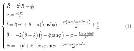
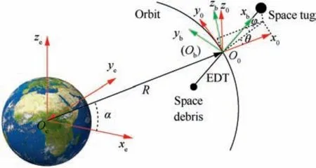
Fig. 1 Schematic diagram of the space EDT system.
wherem=m1+m2and=m1m2/m;m1is the mass of the space tug;m2is the mass of the space debris;Ris the geocentric distance of the EDT system; ˙α is the orbital angular velocity of the EDT system;lis the distance between the tug and the debris;μ is the geocentric gravitational constant;Tis the EDT tension, andTis defined as following:
At the EDT deployment stage, the EDT tension is small,and can be considered to be only related to the friction force of the EDT.Its size is related to the EDT deployment velocity,and the EDT tension can be expressed by the following equation:

wherevlis the deployment velocity of the EDT,aandbare constants evaluated by experiment.19
At the fully deployed stage, the tension force is determined by:

wherel0is the original length of the EDT,ktandctare the elastic stiffness and damping coefficient of the EDT,respectively.16
From Eq. (1), it is obvious that the initial in-plane/out-ofplane angles are immediate and significant factors that affect the variables (¨l,¨θ,¨φ)of the EDT system. Specifically, its effect on¨lmay cause the EDT relaxation(As shown in Fig.2),which may lead to tangle of the EDT easily.In addition,the inappropriate initial in-plane/out-of-plane angles on ¨θ and ¨φ may cause a large swing of in-plane/out-of-plane angle during the deployment process. As shown in Fig. 1, it is not difficult to understand, large swing of in-plane/out-of-plane angle is not conducive to the stability control of the system, and is likely to cause system instability. Therefore, it is necessary to study the dynamic effect on the EDT system caused by initial inplane/out-of-plane angles.
3. Safety metric of EDT deployment
In Section 2.2,it has been found that the variation of initial in/out plane angles have a great influence on the deployment process of EDT. To study the specific impact, the definition of a safety metric of EDT deployment is necessary.
For the tangling problem caused by different initial in/out plane angle on¨l,if the EDT is always tensed during the deployment process, there is no tangling of the EDT (as shown in Fig. 2(a)). In contrast, if the EDT is loose (as shown in Fig. 2(b)), it is easy to cause tangling of the EDT (as shown in Fig. 2(c)). When the length of the EDT is greater than the distance between the space tug and the space debris, the EDT will be loose (the statement is valid only in the assumption of a rigid rod, and when significant deformations of tethers happen in the real case, both positive tension and smaller tether length can happen at the same time). Thus, during the deployment process, when

the EDT is not tangled,wherelt(t)represents the length of the EDT that has been deployed at a specific moment.
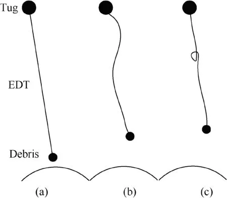
Fig.2 Possible state of the EDT during the deployment process.
The length of the EDT during the deployment process can be expressed as:

wherelmax(t)is the maximum distance between the tug and the debris at the specific moment.
When the distance between the tug and the debris keeps increasing,Eq.(4)can be always satisfied.A sufficient and necessary condition is that the deployment velocity is always positive:

Therefore, the deployment velocity can be used to describe the tangling of the EDT.When the deployment velocity is positive, there are no tangling risks of the EDT; when it is negative, there are tangling risks of the EDT.
In addition,aiming at the swing instability problem of EDT system caused by different initial in/out plane angle on ¨θ and¨φ, the attitude angle β based θ and φ is defined to directly describe the swing amplitude of the in-plane/out-of-plane angles (As shown in Fig. 3).
To obtain the specific expression of β, two right triangles ΔOsABand ΔOsACare constructed, whereCis a point in the connection betweenOsand Earth’s center of massOe. It can be concluded that ΔBACis also a right triangle from the definition of in-plane/out-of-plane angles. AssumingOsA=1, Eq. (7) can be obtained through the Pythagorean theorem:
the system is in the stable swing state.

Applying the cosine theorem to ΔOsBC,the angle β can be deduced as follows:

Generally speaking, for the stability problem in the swing,when the swing amplitude of attitude angle β is small,the system is stable, or it is easy to make the system stable through some control methods. In contrary, if the swing amplitude of attitude angle β is large, the system is unstable, and it is hard to make it stable. So there exists an angle βs, when β is less than βs,the system is considered stable.When β is greater than βs, the system is considered unstable. In other words, when

Therefore, Eqs.(6) and(9) can be used as the safety metric of the EDT system during the deployment process, where the tangling of the EDT can be judged by Eq. (6), and the system instability caused by large swing of θ and φ can be judged by Eq. (9).
4. Numerical examples and analysis
Based on the safety metrics,deployment velocityi(Eq.(6))and angle β (Eq. (9)), several simulation cases have been established to explore the effects of initial in-plane/out-of-plane angles on the EDT system during the deployment.The specific parameters of the EDT system are shown in Table 1,where βsis set tobecause the tether can tangle with the space tug when β reachesfor the specific tug geometry in the research.Here, Case 1 studies the effects of positive initial in-plane angles on the EDT deployment performance with the initial out-of-plane angle of zero;Under the same out-of-plane angle,the effects of negative initial in-plane angles are studied in Case 2.Next,to study the effects of initial out-of-plane angle on the EDT deployment performance, the simulations based on different initial out-of-plane angles with different initial inplane angle are studied in Case 3.
4.1. Case 1
First,we studied the deployment of the EDT with different initial in-plane angles θ of 0,π/6,π/4,π/3,π/2 when the initial outof-plane angle φ is zero. The simulation results of distance between the EDT and the tug, deployment velocity, attitude angle and the EDT tension in the process of the EDT deployment are shown in Fig. 4.
It can be concluded in Fig.4 that the EDT is eventually deployed to a predetermined length.During the deployment process, the deployment velocity is always positive. There is no tangling of the EDT. Simultaneously, the attitude angle does not exceed βsin the whole deployment process. The attitude angle also remains within βsafter deployment, so the deployment process is stable. Thus,the deployment process is safe in this case.

Fig. 3 Connect situation between the EDT and the tug.

Table 1 Specific parameters of the EDT system.
The impact tension of the EDT is high at the later stage because of the high deployment velocity of the debris.According to Eq.(3),when the EDT is tensioned,its elastic and damping characteristics are taken into account. Therefore, the distance between satellites varies violently after the EDT is fully deployed.Then,the EDT length stabilizes to the predetermined length under the damping effect of the EDT.
4.2. Case 2
In this case,we studied the deployment of the EDT with different initial in-plane angleswhen the initial out-of-plane angle φ is zero. The simulation results of the distance between the EDT and the tug, deployment velocity,the EDT tension and attitude angle in the process of the EDT deployment are shown in Fig. 5:
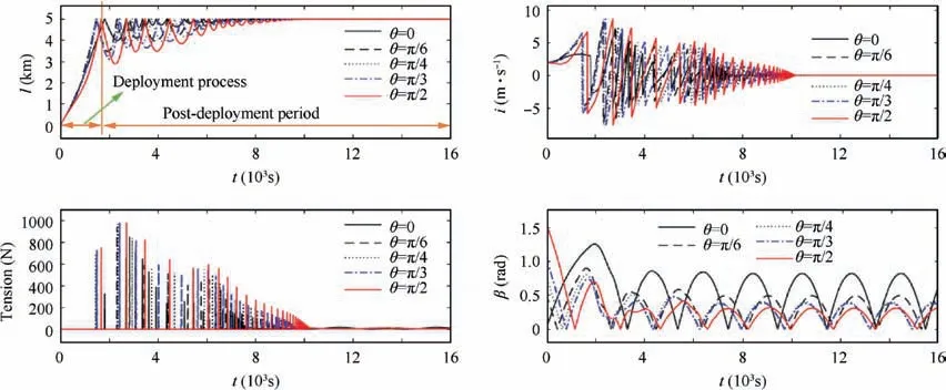
Fig. 4 Simulation results of Case 1.
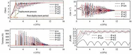
Fig. 5 Simulation results of Case 2.
From Fig.5,it can be concluded that the length of the EDT can be deployed to a predetermined length. However, in the casethe velocity decreases to negative during the deployment process, so there are tangling risks of the EDT.For all cases during the deployment process,the value of angle β keeps increasing and exceeds βs. There may be system instability. Thus, the deployment process is unsafe in this case.
It can be seen from Case 1 and Case 2, when the initial inplane angle is positive, the deployment process is safe, and when the initial in-plane angle is negative,the deployment process is unsafe. The main theoretical reasons are as follows:
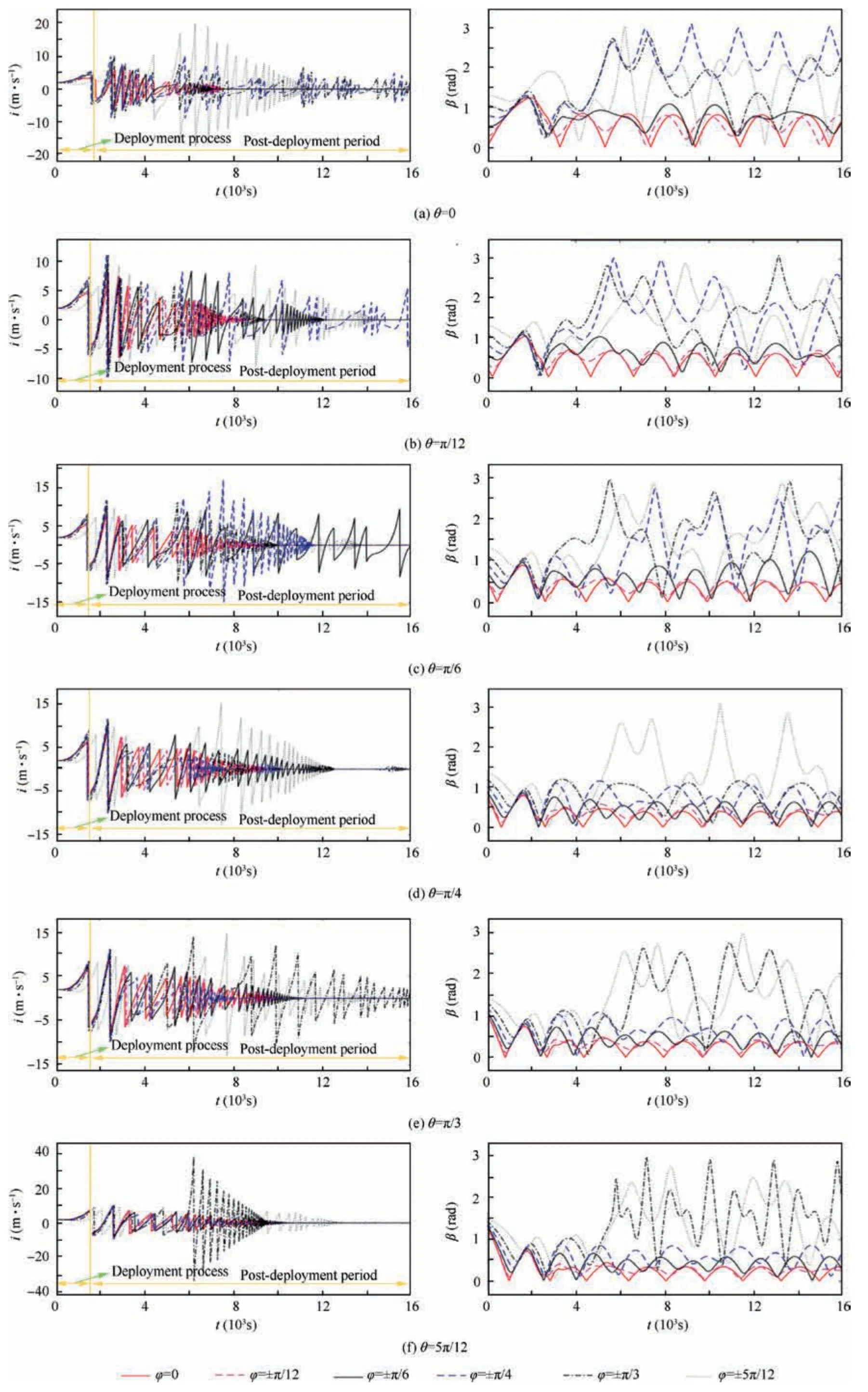
Fig. 6 Simulation result i and β in Case 3 with different initial in-plane angles.
During the deployment process,since the constants a and b in Eq.(2)are small,the effect of the EDT tension on the space debris is relatively small.Thus,the impact of the EDT tension is temporarily ignored in the following analysis. Then, the earth’s gravity on the space debris can be expressed as:

whereRdis the distance from Earth’s center to the space debris’ center.
The centrifugal force of the space debris can be expressed as:

wherevis the tangential velocity of the space debris.
Before the deployment process, the tangential velocity of the space debris is equal to the uniform circumferential velocity of orbit,namely,Fg=Fl.When the initial in-plane angle is positive,the space tug gets a tangential velocity which is opposite to the direction of motion.Therefore,the initial tangential velocity of the space debris becomes less than the uniform circumferential velocity of orbit, thus:

So the orbit altitude of the space debris will be reduced under the action of gravity,which will pull the EDT to spread out.Meanwhile,the orbit descent will reduce β,so the risks of tangling between the EDT and the tug are small, and it is relatively safe to deploy the EDT in Case 1.
When the initial in-plane angle is negative, the space tug gets a tangential velocity, which is in the same direction as the direction of motion.Therefore,the initial tangential velocity of the space debris becomes larger than the uniform circumferential velocity of orbit, thus:

The centrifugal motion of the space debris will cause the angle β to increase, which will cause the tangling between the EDT and the tug. Therefore, it is not safe to deploy the EDT in this Case 2.
4.3. Case 3
In this case,we studied the deployment of the EDT with different initial out-of-plane angles φ of 0, ±π/12, ±π/6, ±π/4,±5π/12 when the initial in-plane angles θ are 0(Fig. 6 (a)),(f)). Deployment velocitiesiand attitude angles β during the EDT deployment are shown as follows respectively:
To analyze the safety of the EDT system with different initial out-of-plane angles during the deployment process, the maximum of angle β, which is defined as βmax, are extracted from Figs. 6(a)-(f) Fig. 6 and represented in Fig. 7. It can be seen that βmaxis significantly enlarged as the absolute value of initial out-of-plane angle increases. Thus, the greater initial out-of-plane angle is,the greater risks of system instability will exist.
Then, according to whether βmaxexceeds βs, the range of initial out-of-plane angle φ can be divided into safe range,transition range and danger range (as shown in Fig. 7). If the initial out-of-plane angle φ is in the safe range,the deployment process is safe. In contrast, the deployment process is unsafe in the danger range. The transition range is the transformation range from the safe case to the unsafe case, and the critical points are in the transition range. It can be seen from Fig. 7 that as the initial in-plane angle θ increases, the value of the critical points also increase,and the absolute value of them are all greater thanTo ensure the safety of the deployment, the initial out-of-plane angle φ should be strictly limited in the safety rangeSimultaneously,the velocity of deployment is always positive in this range (Figs. 6(a)-(f)),so there is no tangling of the EDT.
The above safety range of initial out-of-plane angle is for the debris mass of 500 kg. Besides, debris with different mass is also studied in this paper,and the results are shown in Fig.8.
For the space debris of different masses, βmaxis substantially enlarged as the absolute value of initial out-of-plane angle increases (As shown in Fig. 8), resulting in higher risks of system instability.In the same way of determining the safety range when the mass is 500 kg,the safety ranges of initial outof-plane angle with the debris mass of 100,300,700 and 900 kg are determined and shown in Table 2.Besides,the corresponding figures are Figs. 8(a)-(d).
From the above analysis, it can be seen that as the debris mass increases, the safety range of initial out-of-plane angle decreases. Thus, a small initial out-of-plane angle is expected during the deployment process, especially for the massive debris.
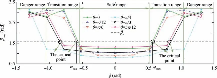
Fig. 7 Variation trend of βmax with different initial out-of-plane angle.
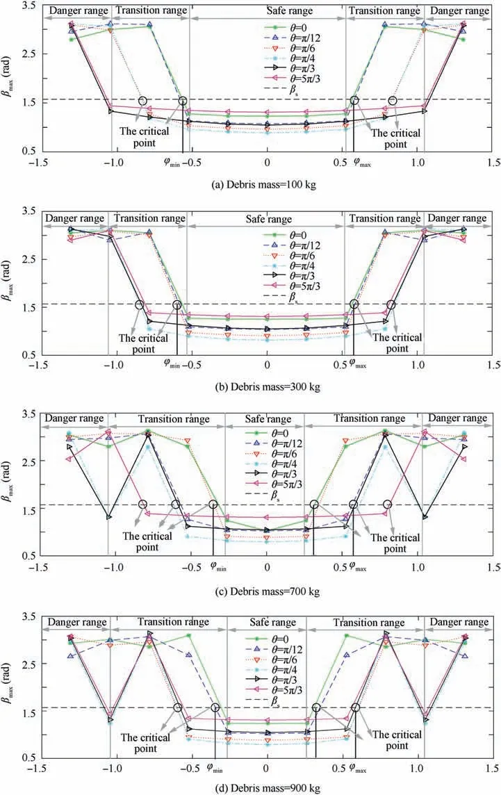
Fig. 8 Variation of βmax with different initial out-of-plane angle at different debris mass.
Hence,the safe range of the initial in-plane/out-of-plane angles during the deployment process is shown in Fig. 9, i.e.,when the in-plane angle of the EDT is positive and the outof-plane angle of the EDT is within the range of (-φthreshold,φthreshold), the deployment process is safe, and the value of φthresholddecreases as the debris mass increases.
5. Conclusions
The space EDT can be used as an effective means to remove the space debris for its low fuel consumption, and the EDT can be deployed under gravity gradient.However,the tangling of EDT and the instability of the EDT system might happen during the deployment process because of the flexibility of the EDT, the risks of which can increase via the initial in-plane/out-of-plane angles that are not within the safe range. This paper analyzed the effects of in-plane/out-of-plane angles on the motion of the EDT system based on a dynamic model established by using the Lagrange approach.Then safety metrics of avoiding the tangling and assessing system stability of the EDT system during the deployment stage were designed.Based on that, several numerical cases were established and simulated. As shown in the simulation results, when the EDT is deployed under the negative in-plane angle or the out-of-plane angle range outside (-φthreshold, φthreshold), there will be higher risks of the tangling of the EDT and system instability. In summary, the initial in-plane angle range insideand the initial out-of-plane angle range inside(-φthreshold, φthreshold) are the safe range for the EDT deployment process. Furthermore, it can be seen that there is large impact tension at the moment that the EDT is fully deployed,and it is easy to break the EDT and destabilize the system.Therefore, the method to reduce the impact tension of the EDT when the EDT is fully deployed should be studied in the future. Simultaneously, the effect of the gravity gradient is very weak at the initial deployment stage, which makes the initial deployment velocity of the EDT necessary, so the method of providing initial velocity should also be studied.In addition, although the above content gives the safe ranges of initial in-plane/out-of-plane angles during the deployment process, the amplitude oscillation of the angle β is still relatively large after deployment. It is not beneficial to generate the Lorentz force and stabilize the system during de-orbit process,so the method of reducing the amplitude oscillation of the angle β also needs further study.

Table 2 The safety ranges of initial out-of-plane angle with different debris mass.
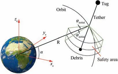
Fig. 9 Safety deployment area of the EDT system.
Declaration of Competing Interest
The authors declare that they have no known competing financial interests or personal relationships that could have appeared to influence the work reported in this paper.
Acknowledgements
This study was co-supported by the National Natural Science Foundation of China (Nos. 51975021, U1913206).
 CHINESE JOURNAL OF AERONAUTICS2021年1期
- CHINESE JOURNAL OF AERONAUTICS的其它文章
- Aerodynamic periodicity of transient aerodynamic forces of flexible plunging airfoils
- Effects of swirl brake axial arrangement on the leakage performance and rotor stability of labyrinth seals
- Experimental and computational investigation of hybrid formation flight for aerodynamic gain at transonic speed
- Tomography-like flow visualization of a hypersonic inward-turning inlet
- Hypersonic reentry trajectory planning by using hybrid fractional-order particle swarm optimization and gravitational search algorithm
- A theoretical and 1-D numerical investigation on a valve/valveless air-breathing pulse detonation engine
