A theoretical and 1-D numerical investigation on a valve/valveless air-breathing pulse detonation engine
Hu QIU, Ch XIONG, Jinling LI
a School of Power and Energy, Northwestern Polytechnical University, Xi’an 710072, China
b State Key Laboratory of Explosion Science and Technology, Beijing Institute of Technology, Beijing 100081, China
KEYWORDS Detonation;Pressure gain characteristics;Propulsive performance;Supersonic internal compression inlet;Valve/valveless;Thermal cycle
Abstract The important operating characteristics of pulsed Pressure Gain Combustion (PGC)propulsion are the pressure gain of the combustor component and the propulsive performance gain of the engine. A ramjet-type valve/valveless air-breathing pulsed detonation engine with a supersonic internal compression inlet is investigated.Based on an ideal thermal cycle,the ideal equivalent pressure ratios (πcb) of the Pulsed Detonation Combustor (PDC) are obtained theoretically which are directly related with the propulsive performance of the engine. By introducing an orifice loss model into the cycles, the critical pressure drop ratios through the orifice for the PDC achieving pressure gain and the engine achieving thrust gain are studied. More influencing factors are investigated by the use of a one-dimensional (1-D) numerical simulation model. The operating characteristics of the pulse detonation engine are investigated with changes of the valve type, the inlet/outlet area ratio of the PDC,the nozzle area ratio,and flight conditions.All these factors can affect πcb of the PDC,and πcb can be optimized by changing the geometry of the engine.The most important influence parameter is the valve type. When using an orifice-type aerodynamic valve, simulation results show that the PDC cannot achieve the pressure gain characteristics. When a supersonic internal compression inlet is introduced to the engine, whether the Pulse Detonation Engine (PDE) can achieve thrust gain comparable with that of an ideal Brayton cycle engine not only is related to the pressure gain of the combustor,but also needs to optimize the engine structure to reduce the total pressure loss.
1. Introduction
Detonation is Pressure Gain Combustion (PGC). Theoretical analysis has shown that1when an engine utilizes the thermal cycle based on detonation combustion, its thermal cycle efficiency would be much higher than that of the traditional Brayton cycle using deflagration combustion.In order to apply the detonation combustion mode to a propulsion system, two kinds of detonation engine structures have been formed,namely,the Pulse Detonation Engine(PDE)and the Continuous Rotating Detonation Engine (CRDE). In addition, the core components of the PDE and the CRDE are the Pulse Detonation Combustor(PDC)and the Continuous Rotating Detonation Combustor (CRDC), respectively. In the PDC,repetitive detonations are initiated by a periodic ignition source, while in the CRDC, detonation wave continuously propagates. Since both types of detonation combustors organize supersonic detonation combustion in a subsonic flow,the gas state in them has strong periodic oscillation characteristics,which will further affect the flow in downstream components.Therefore,these two kinds of engines can be classified as unsteady detonation propulsion.
The PDE has been investigated for many years since 1940s.1A large number of experiments have shown2,3that the specific impulse of a PDE with a single cycle is much higher than that of a traditional engine with constant pressure combustion under the same working conditions. For a PDE with multiple cycles, the experimental results of an air-breathing pulse detonation turbine prototype engine have shown that4the specific thrust is 27% higher than that of a turbojet engine based on the Brayton cycle with an equal compressor ratio. Although there is currently no average pressure data in a PDC to verify that the value is higher than the compressor outlet pressure,the measured propulsive performance of a PDE is comparable to that of a conventional engine at a higher compressor ratio which indirectly reflects the pressure-gain characteristics of the combustor components.
The research of the CRDE began in the 1960s.5,6Since the beginning of this century, more and more countries and research institutions have begun to enter the field.7,8A lot of literature provides the time-averaged pressure in the combustion chamber (defined asPc). According to an experimental investigation of a rocket-type CRDC,9its results have shown that in order to achieve stable propagation of detonation,the supply pressure (defined asPS) of fuel and oxygen must reach 2 to 3 times ofPc. For a ramjet-type CRDC,9the ratio ofPS/Pcis related to the flow area ratio at the head of the combustor (defined asAR_in). WhenAR_inis equal to 0.043,PS/Pcis between 3.4 and 5.66. WhenAR_inis increased to 0.435,PS/Pcis between 1.06 and 1.25. The influence trend ofAR_inandPS/Pcbeing greater than one are consistent with studies by Zhou et al.10The results of a study by Fotia et al.11have shown that whenAR_inis 0.125,PS/Pcmust be greater than 2 to achieve stable propagation of detonation wave. Further experimental investigations by Rankin et al.12have shown thatPS/Pcis slightly less than 1(about 0.93)only whenAR_inis 0.4 and the air supply pressure is 112 kPa.Kindracki et al.13studied the working characteristics of a CRDE with CH4/O2as the reactant, and the peak value of the pressure curve in the CRDC was lower than the supply pressure. Goto et al.14systematically investigated the CRDE propulsion performance under different nozzle throat area convergence ratios (defined as 1/AR_out).When the nozzle throat does not converge,PS/Pcbased on oxygen supply is about 3.2-4.2. When the nozzle throat convergence ratio is raised to 8,PS/Pcis between 1 and 1.1.Rankin et al.15compared the operating characteristics of a CRDC-driven turbine experiment setup and a T-63 engine under the same compressor outlet conditions, and found that the average turbine inlet pressure and output power were comparable.
IfPS/Pcis defined as the pressure ratio of the combustor component (πcb) and the pressure gain is defined as πcb-1,current experimental data indicates that πcbof the CRDC is less than 1. In contrast, currently the total pressure recovery coefficient (total pressure ratio between the outlet and inlet of the combustor)of the main combustion chamber of a traditional gas turbine engine can reach 97%. Moreover, the pressure ratioPS/Pcof the total pressurePSof air at the outlet of the compressor to the static pressurePcin the main combustion zone of the combustor is slightly higher than 1.This value is lower than most of the experimental data of CRDCs mentioned above. In addition, no literature has mentioned the effects of this difference on the propulsion performances of the two types of engines.
The pressure-gain characteristics of a CRDC have been demonstrated by the results of numerical simulation or theoretical analysis. Braun et al.16numerically investigated working characteristics of a CRDC with different exhaust nozzle geometries. Different total pressures of premixed H2-air mixture were imposed as inlet boundary conditions. Results showed that the total pressure gain could reach a mean level of 1.28 (πcbnearly equaled to 2.28) for the CRDC without a nozzle. In Qi et al.’s paper,17an interstage bleeding CRDC for a gas turbine engine was numerically investigated at different compressor pressure ratios, and the pressure ratios of the component CRDC were all higher than 1.77.
The differences of pressure gain characteristics of a CRDC between numerical simulations and experiments are caused by the difference in the inlet geometry and the inlet boundary condition of the combustor. Currently, both fuel and oxidant are continuously injected into a CRDC during an experiment.High pressure generated by detonation will drive combustion products upstream from the combustion chamber, which in turn affects the pressure gain characteristics of the combustor.In most current numerical simulations, this phenomenon is neglected by the use of an inlet boundary condition. A backflow phenomenon also occurs in a valveless PDC.18,19A series of single-cycle tests has been carried out to measure the impulse in a PDC with a porous thrust surface,20and a 76%loss in impulse was observed with a thrust surface blockage ratio of 52% (AR_in=0.46), which means that the pressuregain characteristics of the PDC were affected. However, little work has been conducted numerically or experimentally on a multi-cycle valveless PDC coupled with an inlet.Many investigations have been associated with a PDC with a mechanical valve, and the influence of an inlet is not coupled with the operation of the PDC. Although the ways to achieve detonation in a PDC and a CRDC are different,the factors affecting the characteristics of a pressure-gain combustor are the same,such as inlet/outlet geometry,intake mode/loss,etc.Therefore,this paper focuses on the effects of these factors on a ramjettype PDE coupled with a supersonic internal compression inlet. Firstly, the engine configuration is introduced, including the engine dimension, the valve/orifice model, and the fuel injection model. Then, the thermal cycle performance of the engine is investigated. An equation to calculate the ideal pressure gain of the PDC is deduced. The influence of the orifice model on πcbof the PDC is investigated. Lastly, onedimensional (1-D) numerical simulation is conducted for the PDE. The operating characteristics with different nozzle configurations, injection area ratios, and flight conditions for the PDE with/without a valve are obtained and discussed.
2. Engine configuration, operation, and model
2.1. Engine configuration
The schematic and station designation of the air-breathing PDE are shown in Fig.1.It includes a supersonic inlet,an isolator, a valve, a combustion chamber, and a common nozzle.The air flow enters the isolator after being compressed by the inlet. Then it fills the combustion chamber through the head valve. Fuel is also injected into the combustor, and the resulting mixture is converted to products by combustion.Then the products are discharged from the nozzle. For the PGC engine, to prevent inlet unstart caused by the detonation-induced high-pressure gases in the combustor, an isolator and a valve are required to isolate the chamber flow or pressure wave from traveling into the inlet. The isolator is a section with a long length or a huge volume. The valve can be classified as a mechanical valve and an aerodynamic valve.The mechanical valve is closed during detonation initiation and propagation, but remains open during the filling process.The aerodynamic valve is a valveless design which uses a gasdynamic means to isolate the influence of the combustor on the inlet. The station designation of the engine is also shown in Fig. 1.
2.2. Physical model of engine and numerical methods
To consider the influences of many factors such as valve types,valve loss, dimensions, etc. on the engine performance, a 1-D simulated air-breathing engine model is established here, as shown in Fig. 2. The model is divided into two zones which are connected by a zero-dimensional orifice model21(valve)with a throat areaA3th. The first zone consists of an internal compression inlet and an isolator. The fixed dimensions are:Linlet=0.1 m,A1=0.004 m2,A2=0.0024 m2, andLiso=0.3 m.The second zone consists of a combustion chamber and a convergent-divergent nozzle. The fixed dimensions are:Lcb=0.3 m,A3a=0.02 m2,A9=0.02 m2, andLnzl=0.04 m. The convergent and divergent curves of the nozzle use the Vito Eric hinske formula. The inlet flow area ratio of the combustorAR_in(=A3th/A3a),the outlet flow area ratioAR_out(=A8/A3a),and the nozzle area ratioAR_nzl(=A8/A9) are variables. H2is used as fuel which is injected at the head of the combustion chamber.
Numerical simulation uses a 1-D adiabatic and inviscid model. The Advection Upstream Splitting Method (AUSM)scheme and the third-order Total Variation Diminishing(TVD)Runge-Kutta method are used for spatial and temporal discretization, respectively. The chemical source term is dealt with by using the Strang-splitting method and the fully implicit method.22For a system-level analysis of the PDE performance, it appears unnecessary to resolve the details within a detonation wave front at the expense of excessive computer resources,and the grid size is fixed at dx=1 mm.The left inlet boundary condition is supersonic which is given based on the fight attitude (H) and the Mach number (Ma0). The right side of the model is the pressure outlet boundary condition. The ambient condition is computed according to the flight attitude.
Three nominal species are employed herein, namely, reactants(i.e.,the stoichiometric H2/air mixture),detonation products, and air. The chemical kinetics is modeled by a one-step,irreversible reaction expressed with a single progress variable.The mass production rates of reactants and products, the gas constantR,and the specific heat ratio γ of the mixture are calculated by the method described fully in Ref. 23. Meanwhile,the specific heat ratios and gas constants of the stoichiometric reactants,products,and air(i.e.,γiandRi,i=1,2,3),the heat release of reactantsq,the preexponential factora,and the activation temperatureTaare the same as those in Ref. 24, which are also shown in Table 1. When the reactant equivalent ratio at a certain position(S1)in the combustion chamber reaches a certain value (0.8), a product zone with C-J pressure and temperature will be patched at the head of the combustor to initiate the detonation.

Fig. 1 Schematic and station designation of air-breathing PDE.
2.3. Valve and orifice model
Two kinds of valves are used, i.e., mechanical valve and aerodynamic orifice valve (that is an injection hole). The valve models are coupled into the zero-dimensional orifice model mentioned above. The model framework is based on the reactant injection model discussed in Ref.21,in which a premixed inflow of reactants is being driven by a plenum (upstream)through a slot nozzle that discharges suddenly into an enlarged channel area(downstream).Although the model is introduced for the CRDC,it is also suitable for the PDC and called orifice model here. Given the upstream total pressure, the total temperature of the orifice model, the orifice throat area (A3th),the outlet area, and the static pressure at the downstream valve, all other parameters through the valve can be determined by applying the conservation of mass, momentum,and energy for a steady quasi-one-dimensional inviscid flow across the orifice model.21The zero-dimensional orifice model connects the upstream one-dimensional computational domain with the downstream one by the boundary conditions.
In the mechanical valve mode, when the outlet pressure of the isolator is higher than the inlet pressure of the combustor,the mechanical valve is open and treated as an orifice valve.The total pressure and total temperature at the outlet boundary of the isolator and the static pressure at the inlet boundary of the combustor are the inputs of the orifice model to calculate the other boundary conditions at the outlet of the isolator and the inlet of the combustor.When the head pressure of the combustion chamber is higher than the outlet pressure of the isolator,the valve is closed,and the outlet boundary of the isolator and the inlet boundary of the combustor are treated as a solid wall.
In the aerodynamic orifice valve mode,the flow direction is determined by the pressure difference across the orifice valve.Correspondingly, the upstream and downstream positions of the orifice model will also alternate. When the outlet pressure of the isolator is higher than the inlet pressure of the combustor, the calculations of the boundary conditions for the isolator outlet and the combustor inlet are the same as those in the mechanical valve mode. When the inlet pressure of the combustor is higher, the high-pressure combustion products will flow back into the isolator through the orifice.In this condition, the total pressure and total temperature at the inlet boundary of the combustor and the static pressure at the outlet boundary of the isolator are the inputs of the orifice model to calculate the other boundary conditions.

Fig. 2 Schematic of 1-D air-breathing engine model.
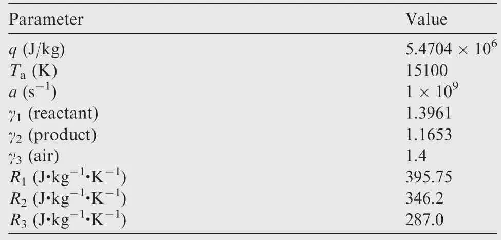
Table 1 Model parameters for detonation of stoichiometric H2-air mixture.
2.4. Fuel injection model
In the engine model, the fuel H2is injected at the end of the isolator, and a steady quasi-one-dimensional mixing model,as shown in Fig.3(where theP,ρ,Tanducorrespond to pressure,density,temperature and velocity,and subscripts 1 and 2 correspond to the state before and after injection,respectively),is used to calculate the mixture status.The mixing channel is of an equal section,and the hydrogen is injected into the channel in a vertical direction. The flow rate of the fuel injection depends on the desired combustion equivalent ratio Φdesat which the mass fraction of air isYa_min. If the mass fraction of air at station 1 (Ya) is higher thanYa_min, the flow rate of the fuel injection depends on Φdes. The mass conservation equation is
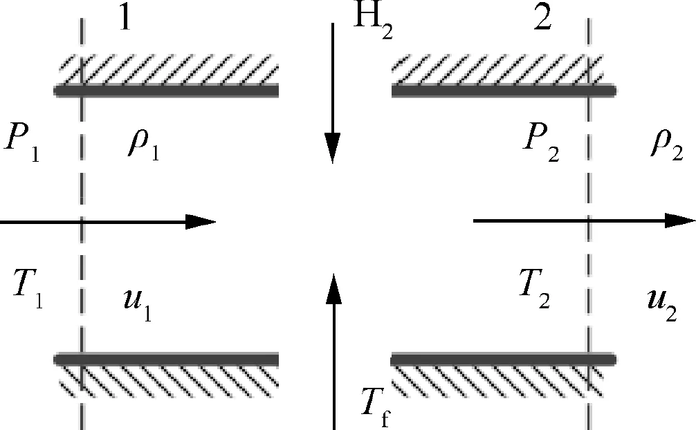
Fig. 3 Quasi-one-dimensional mixing model.

wherefstis the stoichiometric fuel-to-air ratio. Since the fuel injection direction is vertical, the momentum conservation equation is

whereT1* andT2* are the total temperature at stations 1 and 2,respectively.The specific heat capacitiesCp1andCp2are calculated according to the component mass fraction.TfandCpfare the temperature and specific heat capacity of hydrogen which equal to 298 K and 14268 J/(kg·K) respectively. Based on Eqs. (1)-(3) and the ideal gas state equation, the gas states at station 2 can be obtained.
3. Results and discussion
3.1. Theoretical performance of engine
For the 1-D model of the PDE in Fig. 2, all kinds of component losses are involved. The ideal performance of the model can be firstly evaluated according to the ideal detonation cycle outlined by Heiser and Pratt24When the flight attitude (H), the Mach number (Ma0) and equivalence ratio(Φ) equal to 9.3, 2.1 and 1 respectively, theT-S(temperature-entropy) diagram of the ideal detonation cycle is shown in Fig. 4(a). AndS0andCp0correspond to the entropy and specific heat capacity of gas at point 0. Cycle parameters are calculated based on the property parameters as shown in Table 1. TheT-Sdiagrams of the Humphrey cycle and the Brayton cycle are also given in Fig. 4(a).The segment from point 0 to point 3 indicates the adiabatic,isentropic deceleration compression from the freestream static temperatureT0to the combustor static temperatureT3.For the detonation cycle, there is a von Neumann point before the combustion point (CJ point), while for the Humphrey and Brayton cycles, the combustion points are the Constant Volume point (CV point) and the constant pressure point (point 4), respectively. Segments from point 4 to point 9, the CV point to point 9′, and the CJ point to point 9′′indicate the adiabatic, isentropic expansion from the combustor exit static pressure to the freestream static pressureP0. Then the thermal efficiencies of the three cycles can be calculated according to these states, the corresponding formulas of which are derived in Ref. 21. If the mass and enthalpy of the added fuel are considered, the formulas will be modified. The thermal efficiency (ηth_det) of the detonation cycle is

whereMaCJis the Mach number of detonation wave,hspsatisfies the following formula:

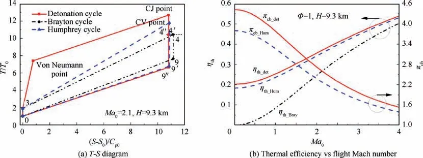
Fig. 4 Comparison between three ideal thermal cycles.
The subscripts(a,m,b)in Eq.(4)represent the air,the mixture,and products,respectively.If the fuel-air ratiofequals to 0 and the specific heat capacityCpmof the mixture equals toCpaof the air,hspis equal to 1,and Eq.(4)is simplified to that in Ref.23.Fig.4(b)shows the thermal efficiencies of the three cycles with different flight Mach numbers. It can be seen that the difference between the thermal efficiency (ηth_Hum) of the Humphrey cycle and the thermal efficiency (ηth_det)of the detonation cycle is within 3%.
It should be pointed out that the detonation cycle and Humphrey cycle analysis in Fig. 4 is actually based on a closed-end piston system.25Each state point in the cycles of Fig. 4(a) corresponds to the thermodynamic state of all the uniform working fluid when the piston moves to a certain position. Meanwhile, the CJ point corresponds to the C-J detonation(PCJ,TCJ),while the CV point corresponds to the constant volume combustion (PCV,TCV). All the effective work of the cycle is transformed into external work. For the open system in Fig.1,the state of the gas at exit 4 of the combustor is periodically oscillated due to pressure gain combustion. If it is assumed that the gas states at the engine outlet 9 is uniform andP9equals toP0, the velocity at the engine outlet 9 can be calculated based on energy conservation as

whereu0is the incoming flow velocity. Since the expansion process does not consider losses, the equivalent total pressure and temperature at exit 4 of the combustor are
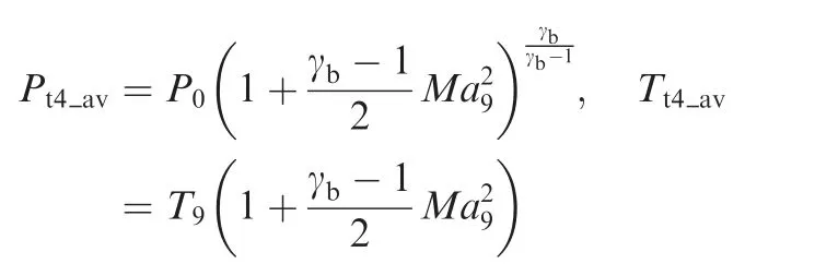
whereT9andMa9are the temperature and Mach number at point 9 ofT-Sdiagram or station 9 of Fig. 1, respectively.Considering the energy conservation in the combustor, the equivalent total temperature also satisfies

whereTt3is the total temperature at point 3 ofT-Sdiagram or station 3 of Fig. 1. This equation indicates that the equivalent point temperature of the detonation and Humphrey cycles is equal to that of the Brayton cycle. That is, the equivalent points are points 4′and 4′′in Fig. 4(a). Then the equivalent pressure ratio of the combustor component can be determined as πcb=Pt4_av/Pt3,wherePt3is the total pressure at point 3 ofT-Sdiagram or station 3 of Fig. 1. The equivalent combustor pressure ratios of the detonation cycle (πcb_det) and the Humphrey cycle (πcb_Hum) under different working conditions are shown in Fig.4(b).It can be seen that there is a huge difference between the component pressure ratios and the combustion pressure ratios (equal toPCJ/Pt3orPCV/Pt3).
For the PGC propulsion,the pressure ratio πcbof the combustor is an important parameter which is directly linked to the propulsion performance. The specific thrustFsof the engine isFs=(1+f)u9-u0. Eq. (5) gives a form ofu9, and another expression is as follows:

This means that the advantage of the PGC propulsion is dependent on the pressure ratio πcbof the combustor. If πcbis lower than 1, the propulsion performance of the engine based on the detonation or Humphrey cycle will be worse than that based on the Brayton cycle.
πcbcan be expressed as

where (Pcomb,Tcomb) are the pressure and temperature after combustion, corresponding to (PCJ,TCJ), (PCV,TCV), and(P4,T4);P3aandT3aare the pressure and temperature at point 3a ofT-Sdiagram or station 3a of Fig.1.The first two items in Eq. (7) depend on the aerodynamic characteristics of the intake structure, which can be called intake pressure drop ratio. For the Brayton cycle (P3a=Pt3,T3a=Tt3), πcb_Brayis equal to 1. For the detonation cycle, πcb_detsatisfies the following equation:

This equation indicates that the pressure ratio of the detonation combustor is dependent on the intake pressure drop ratio,MaCJ, and the intake total temperatureTt3when the heat releaseqis fixed. In addition,MaCJis a function ofqandT3ain which a lowerT3acorresponds to a higherMaCJ.For the conditions (P3a=Pt3,T3a=Tt3) in Fig. 4(b),Tt3increases with an increase of the flight Mach numberMa0,and πcb_detwill decrease according to Eq.(8).When the intake pressure drop ratio,Tt3,andqare fixed,πcbdecreases with an increase ofMaCJ.
Eq.(8)gives the limit pressure ratio of the detonation combustor when(P3a=Pt3,T3a=Tt3).Two factors will lead to a reduction of the limit value.In order to achieve high-frequency operation in the PDC,a high filling speed must be used.It will cause the static temperatureT3abefore the PGC to be lower thanTt3, which leads to a loss of the cycle performance even if the filling process is isentropic. In an actual PGC component, there is a total pressure loss (Pt3a/Pt3<1) when the air fills in the combustor through the head injector or valve.When this happens,T3awill be higher than the isentropic expansion temperature. This will result in the intake pressure drop ratio lower than 1. Since both of the two factors are related to the static pressureP3a, a static pressure recovery coefficient(σinj=P3a/Pt3) can be used to evaluate the influences.
The orifice model21mentioned in Section 2.3 can be introduced into the thermal cycle. If the thermal efficiency of the detonation or Humphrey cycle is equal to that of the Brayton cycle, the critical pressure ratioPt3/P3a(defined as πInj=1/σinj) can be obtained under different flight Mach numbersMa0and flow area ratios (AR_in=A3th/A3a) of the orifice model, as shown in Fig. 5(a). It can be seen that asMa0increases, the critical πInjis significantly reduced, and the equivalent pressure ratios of the PGC component are equal to 1 on the critical curves. When πInjfalls above the critical curves, the detonation cycle has no performance advantage at the same flight condition. The reduction of the flow area ratio will further weaken the pressure gain characteristics of the PGC component. The key reason is that a lower flow area ratio will bring greater total pressure loss.
TheT-Sdiagram of the cycle withMa0=2.1 andAR_in=0.04 at critical πInjis shown in Fig.5(b),and the Brayton cycle is also shown in Fig. 5(b). Comparing Fig. 4(a) with Fig.5(b),it can be seen that the introduction of the orifice will cause losses (point 3 to point 3a), which in turn will increase the system entropy.Although the gas pressure after detonation or constant volume combustion is higher than the combustion pressure (point 4) of the Brayton cycle, the equivalent states are the same,and the state points at the exits of the three cycle engines are also coincident.
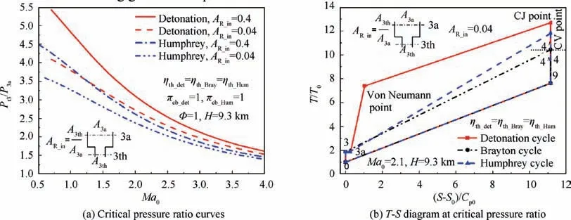
Fig. 5 Influence of intake air loss on cycle performance.
3.2. Operating characteristics of 1-D engine model
The limit propulsive performance of the PDE can be evaluated based on the thermal cycle analysis. The equivalent pressure ratio (Eq. (8)) of the PDC can only be influenced by the air intake loss and detonation properties. Other factors will also affect the PDE characteristics, such as wave propagation,valve type, nozzle, etc., which require numerical simulations.A series of 1-D simulations is conducted to evaluate the performance of the PDE at given flight conditions.Efforts are firstly applied to study the pressure gain of the PDC with a mechanical or aerodynamic valve. A supersonic inlet is also considered.
3.2.1. Flow characteristics
The baseline case is a flight condition involving an altitude ofH=9.3 km and a Mach numberMa0=2.1.The fixed dimensions of the PDE in Fig.2 are mentioned in Section 2.2.If the variable geometry parameters are set to(A3=10A3a,AR_in=0.4,AR_out=0.4,AR_nzl=0.4), the cycle times (Tcycle) are 3 ms and 3.165 ms for the PDEs with a mechanical valve and an aerodynamic valve (an injection hole), respectively. Thex-tdiagrams of the total pressure and the static temperature in one working cycle are shown in Fig. 6, wheretrepresents the instantaneous time made dimensionless with respect to the cycle time andxrepresents different positions along the 1-D PDE model. It can be seen that the high-temperature and high-pressure products formed by the detonation are completely isolated by the mechanical valve. When the detonation wave is initiated and propagating, a strong discontinuity is formed between the new products and the previous cycle product which induces strong compression or shock waves.Meanwhile,since a Laval-type nozzle is used,the compression waves will reflect back and forth in the combustion chamber. The closing of the mechanical valve will also block the flow of the upstream airflow which generates compression waves propagating in the isolator. When an aerodynamic valve is used, it can be seen from the temperature diagram in Fig.6(b)that the combustion products flow back into the isolator through the valve,which induces stronger oscillation propagating compression waves in the isolator.
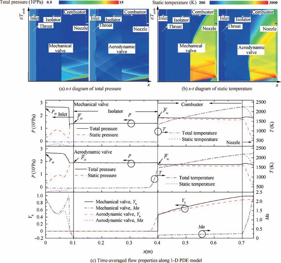
Fig. 6 x-t diagrams of total pressure and static temperature in engine model (AR_in=0.4, AR_out=0.4, AR_nzl=0.4, A3=10A3a).
It can be seen from Fig. 6(a) that since the 1-D flow does not consider the friction loss, there is a partial constant total pressure distribution in the inlet, and a total pressure step exists in the expansion section of the inlet, which is actually caused by a normal shock wave. The normal shock wave can isolate the influence of the downstream pressure oscillation on the inlet. The averaged position of the normal shock wave corresponds to a certain averaged total pressure downstream from the shock wave. For the mechanical valve case with currentA3, the normal shock wave is nearly stable in the fixed position of the inlet expansion section.In the case of the aerodynamic valve with currentA3, the normal shock wave position oscillates very severely which even reaches to the throat of the inlet. A lowerA3will cause the normal shock wave to be spit out of the inlet which will make the inlet unstart.
The time-averaged flow properties along the 1-D PDE model are shown in Fig. 6(c). Since the same flight condition of the PDE with mechanical and aerodynamic valves is used,the inlet total pressure and total temperature are also the same which arePt0=2.686×10⁵Pa andTt0=428.3 K. Although the normal shock wave position under the mechanical valve is near a certain balance point(see Fig.6(a)),the balance point is closer to the exit of the inlet which results in a big total pressure loss.By reducing the exit area of the combustion chamber(corresponds to a lowerAR_out), the balance point of the normal shock wave can be moved to the throat of the inlet,which is useful for reducing the total pressure loss.The average total pressure recovery coefficientthe average total pressure at the exit of inlet)of the inlet with a mechanical valve is 0.52,which is lower than σinlet=0.71 of the inlet with an aerodynamic valve.Meanwhile,there is a significant difference in the time-averaged total pressure at the head of the combustion chamberdownstream from the valve. If the pressure ratio of the PDC component is defined asof the PDC with a mechanical valve is 1.319. However, for the PDC with an aerodynamic valve,although the pressure-gain combustion is achieved by detonation, πcbof the component is 0.924, which does not exhibit component pressure gain characteristics. If the filling and loss effect are neglected,the ideal pressure ratio of the PDC can be calculated by using Eq. (8), which is πcb_ideal=2.736. It can also be seen in Fig. 6(c) that the time-averaged total temperature along the PDC gradually increases and reaches 2264 K and 2198 K near the exit of the PDC with a mechanical valve and an aerodynamic valve,respectively.The lower exit temperature of the PDE with an aerodynamic valve is because some fuel flows out of the engine which causes the mass fraction of productsYbat the exit is lower than that of the PDE with a mechanical valve.
If the instantaneous static pressure recovery coefficient σinjof the valve is defined as the ratio of the instantaneous static downstream pressure of the valve to the upstream total pressure,the instantaneous σinjcurve corresponding to the working condition in Fig.6 is shown in Fig.7.Time histories of the product mass fractionYbdownstream from the valve are also shown in Fig. 7. For the PDE with a mechanical valve, whenYbequals to 1,the valve is closed,and σinjof the valve is much higher than 1 for most of the time. After the valve opens and the fresh mixture starts filling,σinjis lower than 0.7 during the dimensionless time from 0.7 to 1.The mixture intake loss inevitably affects the component pressure gain characteristics, as described in Section 3.1. For the PDE with an aerodynamic valve, σinjis significantly lower than that with a mechanical valve during dimensionless time from 0 to 0.22, which is very detrimental for the pressure gain of the combustor component.The main reason is that there is a backflow through the valve during this time. During the dimensionless time from 0.22 to 0.55, the products return to the combustor again through the valve, and σinjis lower than 0.65. The flow loss will further deteriorate the performance of the combustor. It should be emphasized that the maximum difference between σinjand the total pressure recovery coefficient of the valve is below 0.06.
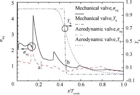
Fig. 7 Time histories of instantaneous static pressure recovery coefficient of valve and mass fraction of products downstream from valve.
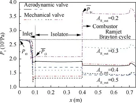
Fig. 8 Time-averaged total pressure distribution along engine with different dimensions (AR_in=0.4).
3.2.2. Effect of nozzle configuration
Variations in the nozzle geometry will affect the operating characteristics of the PDE. A series of nozzle configurations is investigated for the baseline flight condition with a Mach number of 2.1 and an attitude of 9.3 km. The time-averaged total pressure distributions along the PDE corresponding to differentAR_outare shown in Fig. 8. Since the exit area (A9)of the nozzle is equal to the PDC area (A3a), the expansion area ratio (AR_nzl) of the nozzle is equal toAR_out. As can be seen from Fig. 8, there are two steps along each distribution curve. The first step is in the expansion section of the inlet,as shown in Fig. 8. This step reflects the total influence of the normal shock wave and the total pressure loss of the inlet in one cycle. The second step is at the inlet of the combustion chamber. The time-averaged total pressure is attenuated through the aerodynamic valve,that is,the pressure gain characteristics of the PDC component are not achieved by the pressure gain combustion. In contrast, the pressure gain of the PDC component with a mechanical valve is achieved. The interesting result is that the time-averaged total pressure distributions along the PDC with aerodynamic and mechanical valves are comparable at the sameAR_outalthough the pressure gain characteristics of the PDCs are different. These reflect the mass conservation characteristics.The total pressure distribution curve of the ideal Brayton cycle engine is also shown in Fig. 8. Since the component loss is not considered,the distribution curve is a horizontal line.
The operating characteristics of the PDE with different nozzle dimensions are shown in Table 2. It can be seen that asAR_outdecreases, the average inlet total pressure recovery coefficientand the combustion chamber pressure gain characteristicsare improved.Moreover,σallcan be defined aswhich reflects the total pressure loss or pressure gain characteristics of components before the nozzle. The time-averaged total temperature at the exit of the PDEis also shown in Table 2, which is lower than the temperature (2486 K) of constant pressure combustion. The specific thrusts of the PDE are also given in Table 2 which are dimensionless with the specific thrust of the ideal Brayton cycle engine (Fs_Bray=1209 N·s/kg). At current nozzle area ratiosAR_nzl, the propulsive performance of the PDE is lower than that of the ramjet based on the ideal Brayton cycle.
It should be emphasized thatAR_nzlin Table 2 is not the optimal value. WhenAR_outis fixed, the maximum propulsive performance of the PDE can be obtained by changingAR_nzl,as shown in Fig.9,and a change ofAR_nzlhas almost no effect on σinlet, πcb, and σall. Although the use of an aerodynamic valve does not achieve the pressure gain of the PDC components, the propulsive performance difference between the PDE with these two kinds of valve is below 5%.As mentioned in Section 3.2.1, some fuel is flowing out of the PDE with an aerodynamic valve, and there is a gentler gradient zone in the fresh mixture concentration distribution (which leads to the different temperature distribution in Fig.6(b)).The performance difference can be reduced by adjusting the fuel injection strategy. This means that when the engine dimension is unchanged and the use of both types of valves can achieve stable operation, the simple aerodynamic valve is the better choice from the view of engineering application. For the current PDE configuration with an aerodynamic valve and flight condition,AR_out=0.4 is the limit value, below which the internal supersonic inlet will be unstart and the PDE will be in unstable working operation.
The specific thrust ratios of the traditional ramjet(Fs_Ramjet/Fs_Bray) with different σallare also shown in Fig. 9.It can be seen that when σallis comparable, the PDE with a mechanical valve and the ramjet have comparable propulsive performance. σallor the time-averaged total pressure in the combustor can be used to evaluate the performance of the PDE. For the PDE withAR_out=0.2, σallis equal to 1.35,and the specific thrust is 6% higher than that of the ramjet based on the ideal Brayton cycle.

Table 2 Operating characteristics of PDE.
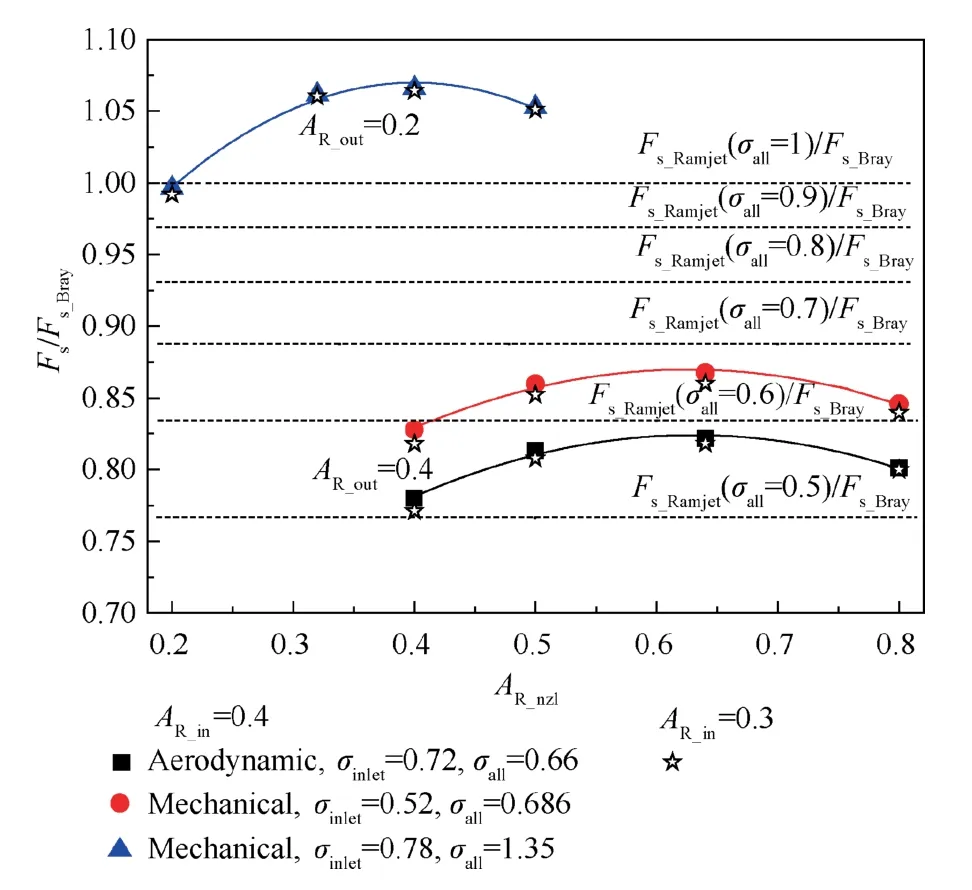
Fig. 9 Specific thrust ratios of PDE vs nozzle area ratio AR_nzl.
3.2.3. Effect of injection area ratio
As mentioned in Section 3.1,the intake flow area ratioAR_inof the PDC can also influence the performance of the PDE. The operating characteristics of the PDE with different (AR_in,AR_out) are shown in Fig. 10. For the current orifice model,a lowerAR_inleads to a lower σinjwhich in turn causes the pressure gain of combustor decrease. It can be seen in Fig. 10(a) that πcbbecomes lower with a lowerAR_inwhenAR_outis fixed.From the perspective of improving the pressure gain characteristics of PDC components, a highAR_inis recommended. However, the propulsive performance of the PDE is dependent on σallwhich includes the influences of the inlet total pressure recovery(σinlet)and the PDC pressure gain(πcb).It can be seen in Fig.10(b)that σallseems to only depend onAR_outregardless of valve types andAR_in. Although πcbdecreases with a decrease ofAR_in, σinletof the inlet is improved. Since the mass flow rate flowing into the engine is fixed because of supersonic flow, these characteristics reflect the flow balance between the inlet and outlet of the PDE.For the conditions of (0.3, 0.2) and (0.3, 0.4), the maximum specific thrust ratio of the PDE can be obtained by changingAR_nzl,as shown in Fig.9 by a star symbol.It can be seen that a change ofAR_inhas few influences on the performance of the PDE.
3.2.4. Effect of flight condition
The influences of flight conditions on the operating characteristics of the PDE are shown in Table 3.The internal supersonic inlet dimensions are the same as before. Since a too low flight Mach number will cause the inlet unstart, the selected Mach numbers in Table 3 are all greater than 2.1.The baseline cases are the cases in Section 3.2.1. As seen in Table 3, the pressure gain(πcb)of the PDC does not change with the flight condition when the inlet total temperature(Tt0)is fixed.Also,an increase ofTt0will make πcbdecrease for the PDE with a mechanical valve. These trends are consistent with the prediction from Eq. (8). However, for the PDE with an aerodynamic valve, it shows an opposite change compared with the prediction from Eq.(8).The key reason is that there is backflow when the pressure in the PDC is higher than that in the isolator. High total temperature will limit the mass flow of the backflow which is beneficial for enhancing the pressure gain of the PDC. For the current fixed PDE dimension, increasing the flight Mach number will decrease the inlet total pressure recovery coefficient (σinlet) which is not good for improving the engine performance.
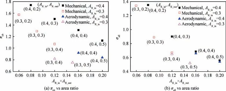
Fig. 10 Operating characteristics of PDE with different AR_in and AR_out.

Table 3 Operating characteristics of PDE at different flight conditions (AR_in=0.4, AR_out=0.4, AR_nzl=0.4).
4. Conclusions
For a Pressure Gain Combustion (PGC) engine, the pressure gain combustion and the pressure gain combustor component are two different concepts. From the perspective of thermal cycle, the equivalent combustor component pressure ratio πcbof a ramjet-type PGC engine can be calculated by a uniform mathematical equation,which is derived based on the principle of energy conservation and constant entropy, and πcbof the combustor is mainly dependent on the intake total temperatureTt3of the combustor when the heat release is fixed. Under the same flight Mach number,the ideal equivalent pressure gain of the detonation combustor component is higher than that of the constant volume combustion chamber. As the Mach number increases (the total temperature of the incoming flow increases), πcbof the component gradually decreases. For an actual detonation chamber, there is a valve at the head of the combustor. To evaluate the influence of the valve on the performance of the thermal cycle, an orifice model (which exists in a real engine) is introduced at the end of the cycle compression process to simulate the combustion chamber filling process through the valve. It is found that the intake total pressure loss and high-speed filling will lead to a low πcb, the value of which is directly related to the propulsive performance of the engine. Moreover, there exists a critical drop pressure ratio (the ratio of the inlet total pressure to the static pressure before combustion, πInj=Pt3/P3a) of the orifice model, at which the thermal efficiency of the detonation/Humphrey cycle is equal to that of the Brayton cycle.
The limit propulsive performance of an Air-breathing Pulse Detonation Engine(APDE)can be evaluated based on a thermal cycle analysis. Other factors will also affect the APDE characteristics, such as inlet, wave propagation, valve type,nozzle dimension, etc., which require numerical simulations.When a supersonic internal compression inlet is applied,a normal shock wave should be anchored in the expansion section of the inlet to isolate the influence of the pressure oscillation produced by the PDC. This normal shock will induce a total pressure loss. Due to the unsteady flow and flow loss, the time-averaged pressure ratio πcbof the PDC is lower than the value calculated by the ideal equation, and πcbis mainly dependent on the inlet total temperature when the flight condition is changed, which is consistent with the prediction of the ideal equation.The influences of mechanical and aerodynamic valves at the PDC head on the characteristics of the PDE are different. When an orifice-type aerodynamic valve is used, πcbof the combustor component is less than 1 (which means that the component does not produce a pressure gain),and πcbcan be increased by reducing the outlet flow area ratioAR_outof the PDC. The use of a mechanical valve can improve πcbof the PDC component. However, to achieve a pressure gain(πcb>1) of the PDC component and acquire a better performance than that of a traditional engine, the engine dimension should be optimally designed, and the average total pressure recovery σallof all components or the time-averaged total pressure in the PDC can be used to evaluate the performance of the PDE whether it is more advantageous than conventional ramjets.
Declaration of Competing Interest
The authors declare that they have no known competing financial interests or personal relationships that could have appeared to influence the work reported in this paper.
Acknowledgements
This work was co-supported by the National Natural Science Foundation of China(No.51676164)and the Natural Science Basic Research Plan in Shaanxi Province of China (No.2020JZ-09).This work was also supported by the opening project of the State Key Laboratory of Explosion Science and Technology at Beijing Institute of Technology (No. KFJJ19-13M).
 CHINESE JOURNAL OF AERONAUTICS2021年1期
- CHINESE JOURNAL OF AERONAUTICS的其它文章
- Tangling and instability effect analysis of initial in-plane/out-of-plane angles on electrodynamic tether deployment under gravity gradient
- Aerodynamic periodicity of transient aerodynamic forces of flexible plunging airfoils
- Effects of swirl brake axial arrangement on the leakage performance and rotor stability of labyrinth seals
- Experimental and computational investigation of hybrid formation flight for aerodynamic gain at transonic speed
- Tomography-like flow visualization of a hypersonic inward-turning inlet
- Hypersonic reentry trajectory planning by using hybrid fractional-order particle swarm optimization and gravitational search algorithm
