Characteristics and mechanisms of turboshaft engine axial compressor casing containment
Zekan HE, Xiaojun GUO, Haijun XUAN,*, Xiaoming SHAN,Xiaojing FAN, Chuanyong CHEN, Weirong HONG
a College of Energy Engineering, Zhejiang University, Hangzhou 310027, China
b Collaborative Innovation Center for Advanced Aero-engine, Beijing 100083, China
c AECC Hunan Aviation Powerplant Research Institute, Zhuzhou 410002, China
KEYWORDS Axial compressor;Blade and casing containment;Damage characteristic;Deformation and failure mechanism
Abstract To investigate the containment characteristics and mechanisms of axial compressor blade and casing in turboshaft engine, experimental and simulation research is conducted on Titanium alloy axial compressor blades and stainless steel simulator casings in this paper.Experiments for four thicknesses (from 0.8 mm to 1.4 mm) of casings are presented on high-speed spin tester.Perforation,ricochet with and without failure of the casings are obtained in test results.Three obvious bulges or dishing region are observed,petaling failure occurs in the first bulge or the third deformation region.Parabolic and elongated dimples are observed at the fracture surface.Finite Element(FE) models with calibrated Johnson-Cook material behavior law are built and analyzed by using explicit dynamic software for a better understanding on the containment behavior.Good agreement is obtained between the experimental observations and numerical predictions.The evolution of the impact force, energy absorption, temperature increase and the cracks’ propagation are analyzed.Three force peaks occur in the impact process. Energy analysis reveals that penetration condition of ricochet with failure leads to most internal energy of the casing.
1. Introduction
In modern commercial and military aviation,a major hazard is the failure of a blade of an aero-engine fan,compressor or turbine at very high rotating speeds due to high cycle fatigue,bird strikes, blade detachment, etc. Failed blade can be released as high-energy fragments which could perforate the engine cowling and damage other accessories,affecting flying performance and even leading to the loss of the airplane.1,2Thus, the designed engine should be capable of containing damage without catching fire.3
Generally, the thickness of the aero-engine containment casing is smaller than or on the order of the characteristic dimension of the blade, and the failed blade is released with a velocity in the range of 150-500 m/s.4Thus, the aeroengine blade/casing impact process falls into the field of thin target impacted by projectile with sub ordinance velocity.5,6For such a problem, both local and global mechanisms contribute significantly to overall target response.7A number of ballistic impact tests and corresponding studies have been carried out to investigate the ballistic performance of aircraft materials (Titanium, Stainless Steel, Aluminum, Inconel,etc.).Recent objectives included:validation of material constitutive relation and failure criterion at high strain rates8;description of performance and models for perforation and penetration in thin targets9; discussion on the influence of target.10
However,the configurations of the blade and the casing are different from conventional projectiles and targets:the blade is always sheet-like and its thickness is much smaller than the dimensions in the other two directions. The casing is circular,which leads to greater difference in smaller engine because of the increasing curvature. As a result of the small clearance between the blade tip and the inner wall of the casing, initial yaw and oblique angle is very large, nearly 90 degrees.11Another limitation of this approach is that ballistic tests cannot simulate the dynamics of a released rotating blade,including interactions with adjacent blades.12Thus, researchers conducted a series of investigations on containment configuration.
A typical approach for studying the containment process is the combination of experimental tests and numerical simulations.13Xuan and Wu14carried out aero-engine turbine blade containment tests using high-speed rotor spin testing facility and made numerical simulations with LS-DYNA. Two major impact regions on the containment ring were found, among which the second one was more seriously damaged. Carney et al.15conducted simulations of a fan blade containment system as well as ballistic tests with blade-like projectile with alternate geometries, aiming at reducing jet engine weight.He et al.16conducted a number of simulations with different mesh sizes and values of both the contact penalty factor and the friction coefficient.Considering the critical rule of material model in the simulations.Zhang et al.17set dynamic relaxation to pre-stress the rotor. Buzyurkin et al.18determined parameters for Johnson-Cook model of titanium alloys VT6, OT4,OT4-0 based on the containment experimental data.
Containment process of blade-out events have been investigated extensively.However,the detailed impact process,deformation and damage characteristics, failure modes and corresponding energy absorption mechanisms were rarely studied, especially for axial compressor blade and casing of turboshaft engine. Therefore, to make a further investigation in the containment characteristics and mechanisms, experiments of released axial compressor blade impacting the simulator casing are conducted in a high-speed spin tester. FE analysis with sufficiently refined mesh and calibrated material model is carried out.The evolution of the impact force,energy absorption, temperature rise and the crack propagation are analyzed.It is worth mentioning that the thermal/aerodynamic effects on the casing containment may be also important,especially for the high-pressure compressor casing. In the current study,the thermal/aerodynamic effects are neglected,considering the current experimental conditions and research depth level.With the deepening of the research in the future,the thermal/aerodynamic effects can be considered and studied in the tests and numerical simulations, which will make the research on the characteristics and mechanisms of compressor casing containment more comprehensive and detailed.
2. Experimental investigations
2.1. Blade and casing
A Ti-6Al-4V axial compressor blisk with 13 blades is selected as the rotor in the test, considering the multi-blade effects.In each test, one blade is set to be released by notching at the root of blade to ensure that the release mass in test was not less than 80% of the whole blade mass,3and the blade release speed is controlled by the length of the notch. Considering the airfoil of the blade, the notching at blade root was conducted by Wire cut Electrical Discharge Machining(WEDM), with tilting of the disk, as shown in Fig. 1(a).
A thin wall cylinder is designed as the casing. The material is Austenitic Stainless Steel 1Cr18Ni9Ti (American standard:AISI 321),which is the material actually used in the axial compressor casing of one turboshaft engine. The heat treatment condition is a combination of solution and aging.For a certain component in aero-engine, the operating speed has already been designed.In the investigation,in order to obtain different experimental results (perforation to ricochet), simulator casings of various thicknesses from 0.8 mm to 1.4 mm at the impacting zone are manufactured. The height of the casings is four times of the axial width of blade tip.
The geometric model and test components are presented in Fig. 1(a). The releasing blade is labeled in dark blue and the remaining blades are in light blue. Geometrical properties of the components are listed in Table 1.
2.2. Experimental set up
Four rotating impact tests are carried out at room temperature on a high-speed spin tester.The experimental structure is illustrated in Fig. 1(b). The rotor is driven by a shaft of the spin tester. The casing is fixed to the mount base through bolts.An enameled wire is glued at the inner surface of the casing.When the blade is released in the vicinity of predetermined speed, the wire is cut by the high speed released blade instantaneously and a trigger signal is transmitted to the spin tester control system and high speed camera. Then the drive motor of spin tester stops immediately and the high speed camera is triggered to record the impact process. Some more detailed descriptions of the experimental setup are available in the article of Xuan and Wu.14
2.3. Results
2.3.1. Deformation and petaling observation
Typical experimental results are listed in Table 2. Perforation and ricochet in oblique impact of non-deforming sphere are defined according to Backman and Finnegan.19Perforation is the complete piecing of a target by the projectile with the projectile completely passes through the target. Sphere rebound from the front surface of the target is defined as ricochet, in which failure may occur.
Casings and released blades of the four tests are shown in Fig. 2. Obviously twisting damage is found at the blade tips and bulges occurred on the casing surfaces in almost all tests.For each casing, distinct deformation starts with a narrow,oblique bulge (bulge I in Fig. 2(d)), which conforms to the shape,position and orientation of the blade tip.Bulge I in each casing can be observed in almost the same dimension,approximately 55 mm length, as shown in Fig. 2(d), which is close to the length of the blade tip (45 mm). Bending of the nearby material, which was defined as ‘‘dishing”,6could also be observed.
For thinner casings (in RI1 and RI2 tests), cracks occur at the end of the bulge I.The ensuing motion of the blade with a combination of residual velocity and roll then pushed the formed sectors, forming the bulge, dishing and various degree of petals. Complete perforation occurred after bulge I in RI1 test, while bulge Ⅱand III did not occur in this test. In RI3 and RI4 tests,with thicker casings,slight bulge II and a larger area of plastic deformation are observed, revealing the impact of blade side and body.For RI2 test,failure and ricochet could be found according to the high speed camera records. Thus,both petaling and bulge II are observed.Then along the blade moving direction, the third deformation region is formed in RI2, RI3 and RI4. No obvious narrow bulge is found. In RI3, petaling occurs in this stage.
The whole deformed region scales a little longer than the height of blade in axial direction and over one quarter of the cylinder circumferentially, which could be divided into 3 distinct regions. Two narrow bulges with various shapes and dimensions exist due to the extended impacting process,which results from the oblique angle. It is observed that twist and fragmentation of the blade would occur. The failure mode of casings is petaling.
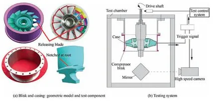
Fig. 1 Experimental set up.
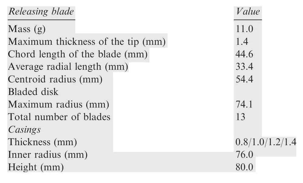
Table 1 Geometrical properties of test components.

Table 2 Experimental results.
2.3.2. Microscopic observations of fracture surfaces
In order to gain a deeper understanding of fracture processes and mechanisms occurring during impact, fracture surface are examined using Scanning Electron Microscope (SEM),parabolic and elongated dimples are observed, as shown in Fig. 3(a) and Fig. 3(b), indicating moderate triaxialities and shear. Impact on ductile material induces the concentrated shear zone, initiating voids. Due to the continuous straining,the voids grow and elongate. The voids then coalesce due to fracture of the thin walls, giving the obtained dimples, and the crack is allowed to grow. This type of behaviour denotes ductile fracture.20
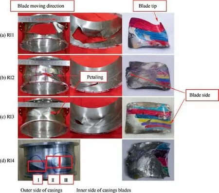
Fig. 2 Post-test component.
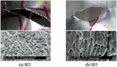
Fig. 3 SEM images of fracture surface.
3. Numerical investigations
3.1. FE model setup
Numerical simulation of the austenitic stainless steel simulator casing impacted by the axial compressor titanium alloy blade is performed by using the explicit FE dynamic software LSDYNA.The numerical configurations used in terms of dimensions are based on the experimental setup. On the basis of the tests, a simplified blisk model is established to save computational time, of which the disk is modeled to a conical ring.In component level study, whirling of the disk due to the unbalance mass caused by the released blade is usually neglected.Hence,the conical ring is considered as a rigid body and only its axial rotation is allowed.21The geometric model is finely meshed with 8-node hexahedron element.Failure cannot occur in less than one element size when using element erosion,22thus,the sensitivity of the mesh size is analyzed.In this study, since there is no shear band, a mesh size of 0.2 mm (at least 4 layers of elements through thickness) is appropriate to capture the deformation and failure observed in tests. There are a total of 1605678 elements and 1928206 nodes in this FE model.
In accordance with the geometric and installation condition,the cross section of the casing is in the plane of symmetry and the top surface is clamped,thus,boundary condition of all nodes fixed at corresponding position is exerted. The reduced integration and a stiffness based hourglass control are also adopted.At the start of the process,the disk is given an initial rotating velocity,which corresponds to the blade release speed in each test. During the whole impacting process, the conical ring keeps rotating with the given speed. Remaining blades keep moving forward as well. FE model is shown in Fig. 4.
Contact is established using the single surface eroding algorithm.Appropriate static and dynamic frictional coefficients of 0.15 are assumed between all surfaces in possible contact. To avoid false penetration, which means the blade penetrates the case without any damage to the case,16contact penalty factor is set to 0.5,23no contact problems are found. Control parameters are also used to control the hourglass,termination of solution and times-step size.
3.2. Constitutive relation and failure criteria
The dynamic behavior of the blades and casing is described by the Johnson-Cook constitutive model,24which expresses the equivalent flow stress as a function of the equivalent plastic strain, strain rate and temperature as:

whereA,B,C,nandmare material constants;σeis the equivalent von Mises stress;εpeis the equivalent plastic strain; ˙ε*is a dimensionless strain rate;T*= (T-Troom)/(Tmelt-Troom) is the homologous temperature.
During the impact, the material behavior is affected by the local temperature variation induced by plastic strain.25The rate of temperature increase is computed from the energy balance by assuming adiabatic conditions as:

where σeqis equivalent von Mises stress; ˙εeqis the equivalent plastic strain rate; ρ is the material density,Cp is the specific heat at constant pressure, and the Taylor-Quinney empirical constant β, which represents the proportion of plastic work converted into heat, is often assigned the value 0.9.26
The three brackets in Eq. (1) describe strain hardening,strain rate sensitivity and temperature softening respectively.Different influences are uncoupled in the formulation, thus,the material characterization procedure becomes straightforward.27
The Johnson-Cook fracture criterion28is based on damage evolution and can be described as:


whereD1...D5are material constants; σ*=σm/, σmis the average of the three normal stresses and σ-is the von Mises equivalent stress; ˙ε*is a dimensionless strain rate;T*= (T-Troom)/(Tmelt-Troom)is the homologous temperature.
3.3. Calibration of material constants
To form the basis for constitutive modeling of casing material(AISI 321), series of material tests at room temperature are carried out,the test methods are referred to Hammer’s work.29Uniaxial compression tests of cylinders in various of strain rates are used to provide true stress versus plastic strain curves,as shown in Fig.5(a).The quasi-static tests are performed on a Instron Testing Machine, using 4 mm(diameter)×6 mm(height) cylinders. Dynamic compression tests are performed on a Split Hopkinson Pressure Bar(SHPB),using 5 mm(diameter)×5 mm(height) cylinders.
In this paper,an additional data fitting capability is used in the strain rate form by introducing the quadratic form proposed by Huh and Kang.30The strain rate form in constitutive equation becomes

For fracture model, quasi-static tensile tests at room temperature with notched and unnotched axisymmetric specimens are conducted in order to obtain constants related to the stress state (D1,D2,D3). The following equations31estimate the σ*and εfin the center region of the spicemen (r=0 in Fig. 5(b)), which give:

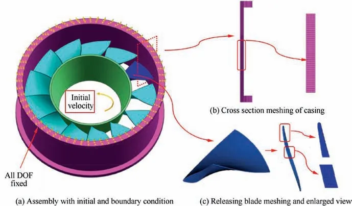
Fig. 4 Finite mesh model.
whereais the minimum cross-sectional radius andRis the radius of the notch, as presented in Fig. 5(b). In this case,d0=2a,dfis the diameter of the failure cross section. Corresponding constants are compiled in Table 3, constants of Ti-6Al-4V come from a reference,32which have been widely validated and used in blades.
3.4. Comparison of damage
The damage extent and high speed video are used to evaluate the reliability of the model. Comparison of casing damage between tests and numerical simulations is presented in Fig. 6. The dash lines corresponded with the colored lines on the rear surface of the casings. Thus, dimensions of the deformation and fracture in axial and circumferential direction could be measured and compared. An approximately quarter circle long deformed region is observed in each casing, which is in good agreement with the experimental observation.
Impacting process of RI3 is presented through high-speed camera record and numerical simulation (Fig. 7), as an additional validation.
3.5. Simulation results and analysis
3.5.1. Peak of forces and energy loss
After the material model is demonstrated to be precise enough to estimate dynamic behavior, details of the high-speed rotating impact are analyzed. For the tests, a small clearance of 1.9 mm between the blade tip and the inner wall of the casing is designed. The blade moves under a combination of translation and self-rotation(ωt).As a result,the initial oblique angle is 83 degrees, as shown in Fig. 8. For each test, the contact force of blade, internal energy of the casing (Ei_c) and kinetic energy of the blade (Ek_b) are plotted as a function of time in Fig.9.Three force peaks,with various value and time point,could be observed for all casings. Experimentally the blade perforated and ricocheted in test RI1 and RI3 respectively,which could be seen more clearly in simulations in Figs. 10 and 11.
The first peak from 6 to 12 kN can be observed at 0.06 ms in each casing, the value of the peak decreases when casing thickness falls.This sharp peak occurs when blade tip contacts the casing.And thus,the bulge forms.A minor fall of the force is observed until the deformed and rolling blade begin to impact by its half front (Fig. 10), which could be considered as the end of first stage. At this bottom point in simulation RI1, RI2 and RI3, force goes to the same value, which can be explained by the shock wave propagation since no failure is predicted.After that the force begins to rise.For simulation RI1 and RI2,a protrusion occurs in the curve and corresponds to the crack propagation. While for simulation RI3 and RI4,convex curves are observed from 0.1 ms to 0.2 ms with a top value of 17 kN. The mountain-shaped force curve is related to the sustained roll of the blade.Stage II can be defined from the first bottom to the next for each curve. The top peak of each simulation is observed in stage III and mid blade impact the casing.In this stage,crack propagation happens in RI3 and the maximum value comes out. Then stage IV starts from 0.26 ms in simulation RI1 and 0.30 ms in other three casings,during which impact weakens obviously. Numerical results at 0.7 ms is considered to be the final status since the force and energy remains unchanged. There is hardly any multi-blade effect on the impacting process, however, slight deformation is found in remaining blades both in tests and simulations. It reveals that the force peaks and bottoms of simulation RI1 occurs earlier than other casings, with lower value as well,which results from an easier crack appearance and propagation.
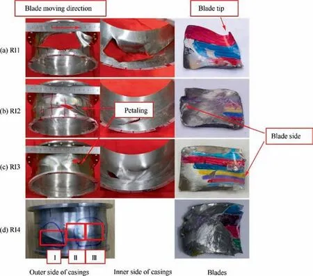
Fig. 6 Comparison of casing damage between tests and numerical simulations.
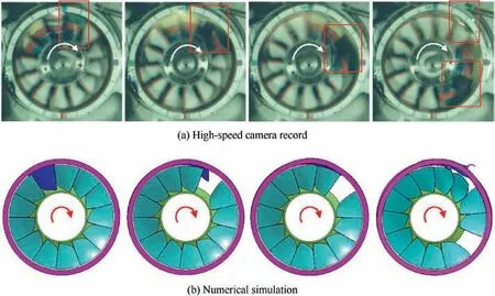
Fig. 7 Impacting process of RI3.
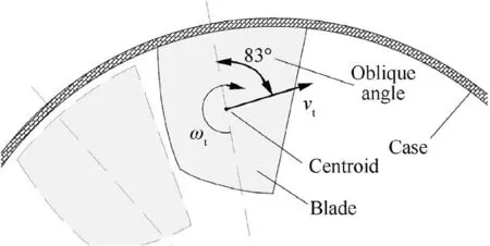
Fig. 8 Initial impact and oblique angle.
Dishing on the casing occurs after the impacting in each stage. Membrane strains and stresses induced by the dishing deformations increase with the growth of dishing, initiating cracks on the casing. If the casing is not resistant enough,petaling failure formed along the cracks and bent continuously.
Ei_cas a function of time is shown in Fig. 9. The most remarkable rise occurs in stage II.At the end of the impacting process,Ei_cin simulation RI2 and RI3 has maximum values of over 400 J, meanwhile,Ek_breduces nearly to 0. For simulation RI1, the energy absorption ability of the casing is limited by the thin wall. While for thicker casing in simulation RI4, blade ricochets with residual velocity. TheEi_cvalues 350 J due to the insufficient contact.It shows that penetration condition of ricochet with failure leads to most internal energy of the casing.
The releasing blade impacts the casing with a centrifugal load of 20.35 kN,which is in the same order of magnitude with the force peaks and approximates to the third peak in the ricochet casings.

Fig. 9 Contact force of blade and Ei_c as a function of time.
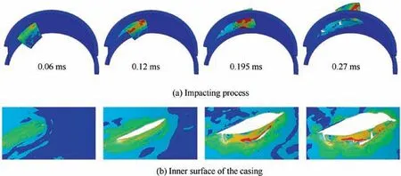
Fig. 10 Deformation and perforation of simulation RI1(Contour plots of Von Mises stress).
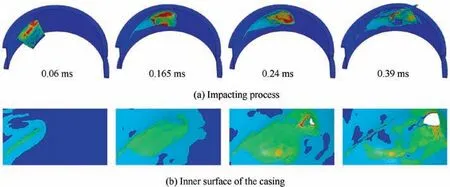
Fig. 11 Deformation, ricochet and failure of simulation RI3 (Contour plots of Von Mises stress).
3.5.2. Temperature rise
In order to investigate the effect of thermal softening in impact process on the failure mechanism of the casing material, four critical elements in Fig. 6 at the bulge and fracture region(A,B,CandD) are selected to analyze the temperature history, as shown in Fig. 12. ElementDgets the highest temperature of 430 K, representing a temperature rise of 140 K. It is predicted that for stainless steel,the breakup of the microstructure into nanosized grains will occur if global deformation is such thatT/Tmelt>0.5.35In this condition, some special deformation and failure mode such as ‘‘Shear Band” will occur, which will significantly change the material strength and failure mechanism. However, for elementD, theT/Tmeltvalues 0.25, revealing that thermal softening effect does not overcome plastic hardening and a shear instability is not predicted.
3.5.3. Crack propagation
To study the mode of crack propagation, simulation RI2 and RI3 are analyzed.Failure region in the dotted line in Fig.6(b)and (c) is magnified in Fig. 13, in which a local cylinder coordinate system is built at the crack tips, and the orthoradial stress σθθduring crack propagation at 0.135 ms and 0.27 ms respectively is showed. It can be noticed that the orthoradial stress is condensed at the crack tips. The orthoradial, radial,longitudinal and shear stress values of the elements in this local cylinder coordinate system can be obtained through simulation. Two elements are selected and further studied as crack tips at 0.18 ms in RI2 and 0.3 ms in RI3,the normal and shear stresses are plotted as a function of time(Fig.14).It turns out that the petaling is produced by high orthoradial, radial and longitudinal tensile stresses.When fracture occurs in impacting stage II, as that in simulation RI2, the predominant stress is the orthoradial stress. Slight difference is found in simulation RI3. It reveals that when failure occurs in impacting stage III, two crack tips are formed. The stresses change in a higher rate because of the intense impact around peak 3 according to Fig. 9. The predominant stress is the longitudinal stress as a result of mid-blade impacting and a higher radial velocity.The deformation of the casing is the result of bending moments created by the motion of the casing material being pushed ahead of the blade.
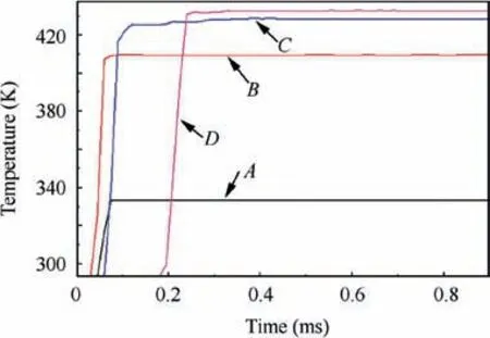
Fig. 12 Temperature of critical elements.

Fig. 13 Contours of orthoradial stress (local axes).
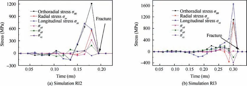
Fig. 14 Evolution of stresses at crack tip.
4. Conclusions
Four containment tests of stainless steel thin wall casings generated by Titanium alloy axial compressor blade are performed. The casings are designed in various thicknesses(from 0.8 mm to 1.4 mm).The blade impacted on the rotation speed 54788-56573 r/min, with tip velocities of over 420 m/s and oblique angle of 83 degrees. Numerical investigations are conducted with calibrated material description. The penetration process, damage characteristics, deformation and failure mechanisms are studied. Following conclusions can be drawn:
Perforation,ricochet with and without failure of the casings are obtained as test results. Three obvious bulges or dishing region could be observed,which in total scaled over one quarter of the cylinder circumferentially.Petaling occurs in the first bulge or the third deformation region.Parabolic and elongated dimples are observed at the fracture surface, denoting ductile fracture.
Numerical simulation shows that the impacting process could be divided into four stages with three impact force peaks for each casing. In different stages, the blade impacts the casing with different parts.Failure would occur during any stage.The first peak is due to the blade tip contact.The second peak corresponds to the crack propagation in thinner casings,while for thicker ones,the mountain-shaped force curve is related to the sustained self-rotation of the blade.The last peak is the largest and occurs when the mid-blade impacts the casing.
Energy analysis reveals that penetration condition of ricochet with failure leads to most internal energy of the casing.Thermal softening effect does not overcome hardening and no shear instability is predicted according to temperature results.
For 1.0 mm and 1.2 mm casings,a study on crack propagation permits to conclude that the orthoradial stress is the predominant stress when crack propagates in stage II, however,the longitudinal stress predominates when fracture occurs in stage III.
Declaration of Competing Interest
The authors declare that they have no known competing financial interests or personal relationships that could have appeared to influence the work reported in this paper.
 CHINESE JOURNAL OF AERONAUTICS2021年1期
- CHINESE JOURNAL OF AERONAUTICS的其它文章
- Tangling and instability effect analysis of initial in-plane/out-of-plane angles on electrodynamic tether deployment under gravity gradient
- Aerodynamic periodicity of transient aerodynamic forces of flexible plunging airfoils
- Effects of swirl brake axial arrangement on the leakage performance and rotor stability of labyrinth seals
- Experimental and computational investigation of hybrid formation flight for aerodynamic gain at transonic speed
- Tomography-like flow visualization of a hypersonic inward-turning inlet
- Hypersonic reentry trajectory planning by using hybrid fractional-order particle swarm optimization and gravitational search algorithm
