Integrated optimization design of smart morphing wing for accurate shape control
Xiaojun GU, Kaike YANG, Manqiao WU, Yahui ZHANG, Jihong ZHU,*,Weihong ZHANG
a Unmanned System Research Institute, Northwestern Polytechnical University, Xi’an 710072, China
b State IJR Center of Aerospace Design and Additive Manufacturing, Northwestern Polytechnical University, Xi’an 710072, China
c Science and Technology on Space Physics Laboratory, China Academy of Launch Vehicle Technology, Beijing 100076, China
KEYWORDS Layout optimization;Morphing wing;Shape memory alloy;Shape morphing;Topology optimization
Abstract Smart morphing wing,which is equipped with smart materials and able to change structural geometry adaptively, can further improve aerodynamic efficiency of aircraft. This paper presents a new integrated layout and topology optimization design for morphing wing driven by shape memory alloys (SMAs). By simultaneously optimizing the layout of smart actuators and topology of wing substrate, the ultimately determined configuration can achieve smooth, continuous and accurate geometric shape changes. In addition, aerodynamic analysis is carried out to compare smart morphing wing with traditional hinged airfoil. Finally, the optimized smart wing structure is constructed and tested to demonstrate and verify the morphing functionality. Application setbacks are also pointed out for further investigation.
1. Introduction
The traditional aircraft wing structure is only designed for several flight conditions by changing rigid operation panels, not for the entire flight envelope. Morphing technologies offer aerodynamic benefits for an aircraft over a wide range of flight conditions.1The key to enable this technology for adaptive structures is smart materials and actuators, such as shape memory alloys (SMAs), piezoelectric materials (PMs), shape memory polymers (SMPs).2Compared with heavy and complex traditional mechanical and hydraulic systems, actuators based on smart materials,particularly SMAs,have the advantages of high energy density,lightweight, ease of control,variable stiffness.3These characteristics offer researchers and designers new possibilities for designing smart morphing structures, whose deformation and load-carrying properties are influenced by many factors, such as type of base-structures,material properties, layout and type of smart actuators.4
There have been extensive researches focusing on designs of smart morphing structures in aerospace applications. SMAs was utilized in an engine nozzle on a Boeing commercial aircraft to reduce jet noise and increase fuel efficiency.5Variable-geometry chevrons, which are actuated using SMAs curved beams, improve the mixing of the free stream air and the fan stream.6A variable-sweep wing actuated by SMA ribbons on the spar was investigated.7SMA torque tube actuators have been used to control the morphing wingtip, which can improve maneuverability and efficiency.8The potential use of this system is to fold the F-18 wing, which can get 80% reduction in actuator weight.9Piezoelectric materials can produce large output forces and high frequency responses.10,11In several studies, these materials were used to control the roll and pitch by morphing the trailing edge near the wingtips, reduce the vibration of helicopter with active rotor trailing-edge flaps.12Also, compliant base-structure13and functional wing skins14,15have been investigated for morphing wing designs. Despite the large number of studies on morphing structures, the researches above are mainly based on subjective design or through trial and error. Following works focus on the optimization to improve the performance of smart morphing systems. A general design optimization framework was proposed by Hartl et al.16for the consideration of any SMA component or assembly of such components that applies when the set of design variables includes many members. This optimization method was used to optimize the variable-geometry chevrons to improve the SMA actuators efficiency.17Yang et al.4presented an investigation of width and thickness distribution optimization of the bi-morph piezoelectric actuators and wing skin on a compliant morphing wing for maximizing the system’s performance.Henry et al.18investigated the optimal structural parameters of distributed piezoelectric actuators in smart morphing wing application. It was shown that the performance can be significantly improved through width and thickness distribution optimization of the bi-morph piezoelectric actuators. Gu et al.19proposed an efficient structural optimization approach for SMAs with respect to fatigue.A nonparametric approach based on optimality criteria was applied to change the structural configuration.
Despite these recent developments, optimization design approaches on smart morphing system often neglect the coupling relation between actuator and base-structure. However,the deformation and load-carrying properties of smart morphing structures are influenced by many factors, such as structural configuration of base-structures, material properties,layout and type of smart actuators. Therefore, motivated by intelligent, lightweight and integrated design,20we propose a new integrated optimization method for smart morphing structures. Morphing wing actuated by SMA wires is utilized to demonstrate the methodology,which also allows optimization design of morphing structure with other actuating components such as rods, beams and shells. To achieve precise shape control, the actuators’ locations and host structural topology are optimized synchronously as shown in Fig. 1. The multi-point constraints (MPC) method is used to build ‘perfect bonding’connections between surface attached actuators and base structures. Once the SMA actuators are relocated in the optimization process, MPC can be easily established instead of tedious re-meshing procedure. Other benefits such as accurate geometry descriptions of actuators can be obtained.
The remainder of this paper is organized as follows. In Section 2, the optimization model is formulated mathematically.Then the selected leading edge and trailing edge are optimized using proposed method,aerodynamic characteristics are analyzed in Section 3. Section 4 presents a 3D printed smart morphing wing and its deformation is tested, before conclusions are given in Section 5.

Fig. 1 Schematic for integrated optimization of smart morphing wing.

Fig. 2 Illustration of MPC connection.

Fig. 3 FCM approximations of actuators and design domain boundary.
2. Optimization methods
In this study,SMA wires are embedded in the base-structure to provide the actuation force. As illustrated in Fig. 2, the MPC method is utilized to model the bonding between SMA actuators and base structure, where they are discretized using beam elements and shell elements, respectively. The displacement boundary condition and MPC equations can be organized as the following linear equations


Fig. 4 Stress-strain curve of SMA at different temperature.

Fig. 5 Young’s modulus and negative expansion coefficient.

Fig. 6 Pressure coefficient of airfoil in desired shape.

Fig. 7 Aerodynamic loads of airfoil.
where u is the global displacement vector. Sparse coefficient matrix H has non-zero values only in positions related to MPC connections and boundary conditions. When actuator moves to another place,only matrix H is updated to efficiently rebuild the MPC connections of the finite element model.Thus, the finite element equilibrium of SMA embedded structure is finally obtained as4

Kuuis mechanical stiffness matrix, λ is Lagrange multipliers,FSMAand Fextare the SMA actuation force vector and the external mechanical load vector, respectively.
In this work, desired wing shapes are specified in advance for adaptive purpose. However, the rib layout and actuators’ locations of aerofoil are undetermined. This is inverse to the usual structural problem of computing the displacements due to a given actuation. The desired structural shapes are achieved by combined action of SMA wire actuation and additional aerodynamic load. Normally, minimizing the shape error function defined as a sum of squared errors between desired and achieved shapes21,22is considered.

where ωkis the weighting factor, which is chosen by the designer.mis the observation points number. akand ukare the specified and simulated displacements of observation pointk.
With static air load and SMA actuation force, minimizing the total compliance of composite wing structure is chosen as the design objective in the integrated optimization method.For achieving desired wing shape, the shape error functionErin Eq. (3) is constrained below a small value, which is defined as δ in Eq. (4). Two types of design variables are employed,namely the geometrical location variable ξj= (ξj,x1,ξj,x2,ξj,θ),and the pseudo-density variable ηiof base structure. ηidefines the material distribution of theith element.ξjdefines the location of thejth SMA actuator during the optimization iterations. Here, ξj,x1and ξj,x2describe the translation movements of thejth actuator, ξj,θdescribes the angular movement of thejth actuator. The integrated optimization model can be defined as

Fig 8 Flowchart for integrated optimization of smart morphing wing.
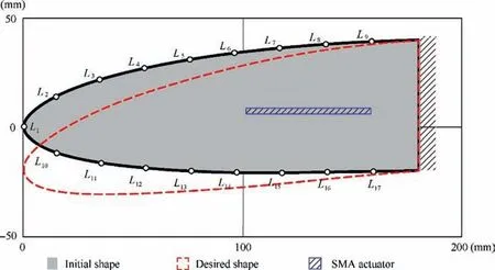
Fig. 9 Dimensions of design leading edge and chosen observation points.

Fig. 10 Geometry approximation of actuator and global design domain (leading edge).

whereIandJare the numbers of density variables and SMA actuators,respectively.Cand u~define the compliance and displacement of the smart wing structure under aerodynamic loads.Vfracis the material volume fraction of the basestructure design domain with an upper limit ofV0.η andare the lower and upper bounds of pseudo-density variables,their values usually take 0.001 and 1. Ωj, Ωj1and Ωj2denote the areas of thejth,j1th andj2th SMA actuators, respectively.Ωddenotes the global design domain.
When including design dependent loads such as gravity to the topology optimization, the popularly used SIMP interpretation model will unfortunately lead to localized deformation in the low density areas.23To avoid this problem, a modified material interpolation model proposed by Zhu et al.24is used here.


Fig. 11 Leading edge optimization configuration at iteration 0, 10, 20 and 40.
E(i) andE0(i) denote the corresponding Young’s modulus to density variable ηiand the value of a solid element.pis the penalty factor andris polynomial coefficient factor.Normally,pandrare chosen as 4 and 1/16.
The Finite Circle Method (FCM)25is used here to prevent overlapping of SMA wire actuators and keep all the actuators inside the design domain.The boundary of design domain and SMA actuators are approximated by a series of circles, which is illustrated in Fig. 3.
To use efficient gradient-based optimization algorithm such as GCMMA,26the derivatives of objective and constraint functions with respect to two types of design variables are obtained directly or by adjoint state method. Then, these two types of design variables are updated according to previously obtained sensitivity information.For the detailed derivation of sensitivity to design variables, see authors’ previous work.4
3. Numerical examples
In this section,the proposed integrated optimization method is used to design NACA2510 morphing airfoil for accurate shape control. For the rotation degree of actuators, the anticlockwise direction is regarded as the positive direction.In this example, base-structure is made of SL5170 epoxy resin with Young’s modulus of 2460 MPa and Poisson’s ratio of 0.23,SMA wires with diameter of 1.2 mm are used as actuators.The austenite finish temperature of the SMA wires is 70°C.The stress-strain curves of the wires are obtained at temperature of 26°C and 75°C, respectively. As shown in Fig. 4, the material is martensite at temperature of 26°C,and austenite at temperature of 75°C. The Young’s modulus of martensite and austenite are 27.3 GPa and 46.7 GPa,respectively. Instead of using nonlinear constitutive model to compute the actuating force of SMA wires, temperature dependent Young’s modulus and negative expansion coefficient are used to simplify the optimization process. They are determined according to experimental measurements as shown in Fig. 5.

Fig. 12 Optimized configuration of leading edge.
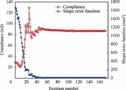
Fig. 13 Convergence history of compliance and shape error function (leading edge).

Fig. 14 Convergence history of constraints (leading edge).

Fig. 15 Optimized configuration of leading edge (6% actuation strain).
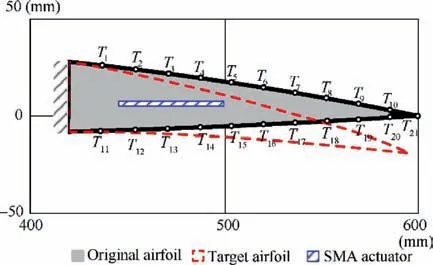
Fig. 16 Overall dimensions of trailing edge and chosen observation points.

Fig. 17 Geometry approximation of actuator and global design domain (trailing edge).

Table 1 Displacement of observation points at leading edge.

Fig. 18 Trailing edge optimization configuration at iteration 0, 10, 40 and 80.

Fig. 19 Optimized configuration of trailing edge.

Table 2 Displacement of observation points at trailing edge.
The aerodynamic loads are assumed to be constant during the wing morphing process. Fig. 6 shows the pressure coefficient of the airfoil in the specified wing shape, with the attack angle of 0°, Mach number of 0.06 (20 m/s) and standard sea level condition.Removing singularities,the aerodynamic loads can be calculated according to the following equations:

whereFxiandCp,xiare the aerodynamic loads and pressure coefficient at chord lengthXi,respectively. ρ is the air density;vis the flight speed.Lis the chord length,which is 0.6 m in this case.The aerodynamic loads of the airfoil are further depicted in Fig. 7.
The base structure is discretized using four-node shell elements with first-order shear deformation.27SMA wire actuator is discretized with 2D beam element.The parametric finite element models of SMA composited wing structures are established using ANSYS Parametric Design Language (APDL).Structural responses and their sensitivities information are computed and then outputted to GCMMA algorithm programmed based on FORTRAN.Fig.8 illustrates the flowchart for integrated optimization of smart morphing wing.

Fig. 20 Convergence history of compliance and shape error function (trailing edge).

Fig. 21 Convergence history of constraints (trailing edge).

Fig. 22 Optimized configuration of trailing edge (6% actuation strain).

Fig. 23 Geometric comparison of smart morphing wing and traditional mechanical wing.
3.1. Optimization of leading edge of the wing
Fig. 9 shows the detailed geometry of leading edge and the chosen observation points. The outer edge is the non-design domain (black region in Fig. 9) and meshed by 271 shell elements.The internal design domain is meshed by 4195 shell elements. The thickness of the plane structure is 4 mm. A SMA wire actuator with the length of 60 mm is embedded in the design domain.The FCM is utilized to keep the actuator inside the global design domain. The contours of SMA actuator and the boundary of global design domain are approximated by a series of circles as illustrated in Fig. 10.
The desired leading edge shape is described by deflections of the chosen 17 observation points. The shape error functionEris established using the 17 observation points with all the weighting factor ω=1.The upper bound of shape error function and volume fraction are chosen δ=10 mm2andV0=30%, respectively. The optimization process shown in Fig.8 is established for smart morphing leading edge and converged in 173 iterations. Iterations 0, 10, 20 and 40 are shown in Fig. 11. The actuators are automatically located to find proper actuation positions,meanwhile base structural configuration connects the actuators to amplify the deformations of SMA wires for desired leading edge shape (see Fig. 12).
The displacements of observation points are summarized in Table 1. The maximum shape error between the original configuration and morphed configuration is 1.63 mm, which located at observation pointL1. The position and angle of actuator change from (130, -4, 0°) to (131.44, -0.93, 1.74°).The convergence history of the response functions is shown in Figs. 13 and 14.
From the optimization convergence history, we can see,during iteration 10 to 30, The compliance, volume fraction and other constraints function are jumping around, while the shape error function decreases dramatically. This shows that the actuator update its position and angle.A general load carrying path is formed due to the matching of base-structure and actuator, then the compliance of the system changes. After that, the actuator finds favorable position and angle for actuation, the weak elements of base-structure are eliminated,which forms a clear structural pattern. With the fine adjustments of actuator’s positions and angles, which guarantee the connectivity and actuating efficiency, the final load path is established.
It is noticeable that the actuation capability of SMA wire has great influence on the optimized smart morphing airfoil. Low bending stiffness airfoil designs are always related with limited actuation force of SMA wire. If we improve the actuation strain of SMA wire from 3% (as the one in Fig. 12) to 6%, smart morphing leading edge with better load-bearing performance can be obtained (see Fig. 15). Enhanced hinge structure with more branches is obtained as marked by the red circle. The compliance of leading edge under aerodynamic loads decreases from 86.88 mJ to 23.62 mJ.

Fig. 24 Aerodynamic performances of two type airfoil.
3.2. Optimization of trailing edge of the wing
Similar to the leading edge, the trailing edge is also optimized using the same approach. Fig. 16 describes the detailed geometry of trailing edge and the chosen observation points. The geometry approximation of actuator and global design domain using FCM is shown in Fig.17.The non-design domain(black outer edge in Fig. 16) is meshed by 374 shell elements. The internal design domain is meshed by 3297 shell elements. The same SMA wire actuator with the length of 60 mm is embedded in the design domain. The desired trailing edge shape is described by deflections of the chosen 21 observation points with all the weighting factor ω=1.The upper bound of shape error function and volume fraction are chosen δ=10 mm2andV0=30%, respectively.
The trailing edge optimization process converged in 164 iterations. Iterations 0, 10, 40 and 80 are shown in Fig. 18.The final optimized configuration of trailing edge is shown in Fig. 19. The displacements of observation points are listed in Table 2. The maximum shape error between the original configuration and morphed configuration is-1.20 mm, which located at observation pointT12. The position and angle of actuator change from (478, 2, 0°) to (462.78, 0, -4.67°). The convergence history of the response functions is drawn in Figs. 20 and 21.
If we improve the actuation strain of SMA wire from 3%(as the one in Fig. 19) to 6%, smart morphing trailing edge with better load-bearing performance can be obtained (see Fig. 22). As we can see, more material of base wing structure gathered around the wing skin. Thus, the compliance of trailing edge under aerodynamic loads decreases from 20.80 mJ to 5.67 mJ.
From the leading edge and trailing edge optimization processes, we can see that desired airfoil deformations are achieved with fine precision. The optimized airfoil configurations, which meet design requirements on deformation and actuation, are valuable references for relevant engineering.
3.3. Analysis of aerodynamic characteristics
In this section, the aerodynamic characteristics of traditional hinged wing and the smart morphing wing are compared in terms of lift coefficient,drag coefficient and flow field distribution. The optimized leading edge and trailing edge shape are used to construct the smart morphing wing. Wing using traditional slats and flaps, which is shown in Fig. 23, would bring gaps between slats/flaps and the wing when the slats or flaps rotate.The disadvantage of introduced gap is loss of lift.However,for the purpose of simplifying simulation model,this gap influence on aerodynamic characteristics is ignored. The compared two types of airfoils have the same vertical displacement after deflection, but the traditional one has turning angle with discontinuous slope on the surface.
CFD analysis of the two-dimensional subsonic flow over these two type airfoils at various angles of attack is presented.The flow of incompressible and viscous fluid with the speed of 20 m/s is considered here.The angle of attack varies from-5°to 10°. Lift Coefficient (CL) and Drag Coefficient (CD) are determined. Aerodynamic performances of two type airfoils are plotted in Fig. 24.

Fig. 25 Airflow pressure distribution characteristics of two type airfoil at angle of attack of 4°, 6° and 8°.
As shown in Fig. 24(a), these two types of airfoils have almost the same lift coefficient when the angle of attack is negative. When the attack angle is around 0°, the traditional airfoil has slightly bigger lift coefficient. With the increase of attack angle,the smart morphing wing has about 37.9%bigger lift coefficient than traditional one. That’s because when the angle of attack is above 7°,the boundary layer separates from the airfoil surface. Consequently, lift coefficient and aerodynamic performance decrease rapidly. However, the smart morphing wing,which is able to change shape in smooth and continuous manner, can reduce boundary layer separation,and increase the critical angle of attack.Fig.24(b)shows the drag coefficient variation with the angle of attack. At the same angle of attack,the smart morphing wing has the smaller drag coefficient than traditional one.The lift-to-drag ratioL/Dvariation with the angle of attack is plotted in Fig. 24(c). The maximumL/Dof smart morphing wing is 15.01 when angle of attack is 2.8°, while the maximumL/Dfor traditional wing is 12.21 when angle of attack is 4°.Moreover,L/Dcurve of smart morphing wing at positive angle of attack is smooth, which indicates better airflow stability on wing surface. Fig. 24(d)shows the curve of lift coefficient against drag coefficient. At the same lift coefficient, the smart morphing wing has the smaller drag coefficient compared to traditional wing.
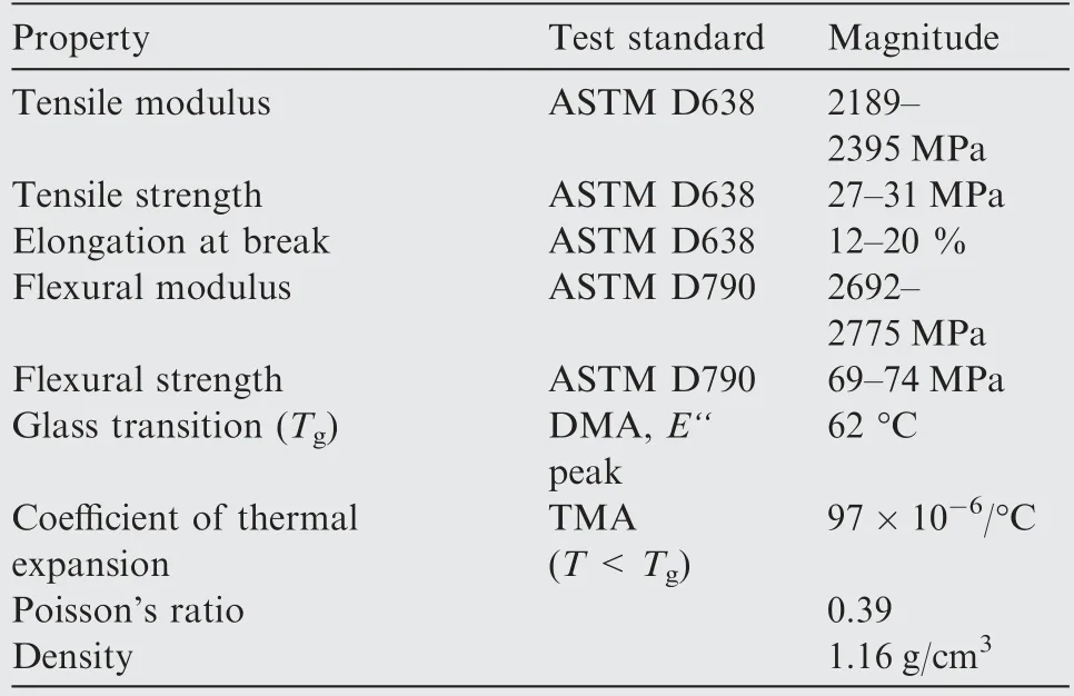
Table 3 Physical characteristics of SPR6000B epoxy resin(15 min UV post-cure).

Fig. 26 Simulated deformation of smart morphing wing.

Fig. 27 3D printed smart morphing wing.

Fig. 28 Deformation of 3D printed smart morphing wing.
Fig. 25 shows the comparison of airflow pressure distribution characteristics of two type airfoils at different angle of attack. When angle of attack is 4° (shown in Fig. 25(a) and(b)),airflow pressure distribution is smooth on both airfoil surface. Small shear vortex is formed near trailing edge. Separation vortex gets bigger along with the increase of angle of attack.When the angle of attack increases to 6°,pressure concentration is more obvious on traditional airfoil than smart morphing airfoil, shown in Fig. 25(c) and (d). With continued increase of angle of attack,airflow instability occurs near trailing edge of traditional airfoil, however, pressure distribution on smart morphing wing is still smooth, see Fig. 25(e) and(f). This shows that the separation vortex already covered on trailing edge of traditional airfoil and detached from the surface.It further implies that smooth and continuous smart morphing wing can delay airflow separation and keep the local flow attached for larger attack angle.
4. Experimental validation and application setbacks
The above work proves that smart morphing wing has good aerodynamic performance due to its smooth and continuous deformation. In this section, the actual deformation of smart morphing wing actuated by SMA wires is experimentally tested. Firstly, the CAD models of leading edge and trailing edge are reconstructed according to the optimization results.Then, the geometrically nonlinear finite element analysis is implemented for accurate structural large deformation responses. The material used for the base-structure is SPR6000B epoxy resin, which is used for stereolithography(SL) additive manufacturing (3D printing). The material parameters are shown in Table 3.The simulated deformations of leading edge and trailing edge are shown in Fig. 26.
As depicted in Fig. 26(a), the lower surface of leading edge deformed outward.Similarly,the lower surface of trailing edge deformed inward (see Fig. 26(b)). The causes for this phenomenon is analyzed as following.In the optimization results,there are some weak elements to support the airfoil skin.However, after removing the weak elements in the reconstructed model, the wing skin surface is buckling under compression stress.
Then, the reconstructed structures are printed out by a SPS350B 3D printer (Shaanxi Hengtong Intelligent Machine Co., Ltd.). The machine uses a UV laser beam with power of 220 mW, diameter of 0.12 mm, scanning speed of 6500 mm/s, and layer thickness of 0.1 mm. Fig. 27 shows the fabricated parts of the testing smart morphing wing.The SMA actuators are assembled in the optimized position.Similar with the finite element analysis result, the lower surfaces are also buckling under compression stress as shown in Fig. 28. To overcome this defect,the lower surface can be designed as a withdrawing type. This type of structure can be found in other smart morphing wing design.28Also, special compressible elastic wing skin with certain bending stiffness needs to be developed.However, aforementioned solutions require extensive researches in the future, thus is not presented in this paper.
5. Conclusions
(1)This work developed a new integrated optimization method for smart morphing wing design. For expanding the design space, MPC-based finite element description has been used.Numerical results show that two kinds of design variables,i.e. the locations of SMA wire actuators and base structural topology both facilitate precise shape morphing of the system.Deformations of smart morphing leading edge and trailing edge are well controlled. The aerodynamic characteristics of traditional hinged wing and the smart morphing wing are compared in terms of lift coefficient,drag coefficient and flow field distribution. Finally, the optimized smart morphing wing is printed out by a 3D printer. Shape morphing precision of SMA actuated wing is tested experimentally and compared with finite element analysis results.
(2) In terms of practical engineering, the problem of buckling surface and limited actuating force should be solved. In terms of numerical methods, the present integrated optimization method is based on small deformation assumption and simplified constitutive laws of SMA materials.For large deformation control, precise numerical modeling considering nonlinear factors should be adopted in the future work.
Declaration of Competing Interest
The authors declare that they have no known competing financial interests or personal relationships that could have appeared to influence the work reported in this paper.
Acknowledgements
This work is supported by National Natural Science Foundation of China (Nos. 11802243 and 11902258), Natural Science Foundation of Shaanxi Province (No. 2019JQ-176), Key Project of NSFC(Nos.51790171,51761145111 and 51735005)and NSFC for Excellent Young Scholars (No. 11722219).
 CHINESE JOURNAL OF AERONAUTICS2021年1期
- CHINESE JOURNAL OF AERONAUTICS的其它文章
- Tangling and instability effect analysis of initial in-plane/out-of-plane angles on electrodynamic tether deployment under gravity gradient
- Aerodynamic periodicity of transient aerodynamic forces of flexible plunging airfoils
- Effects of swirl brake axial arrangement on the leakage performance and rotor stability of labyrinth seals
- Experimental and computational investigation of hybrid formation flight for aerodynamic gain at transonic speed
- Tomography-like flow visualization of a hypersonic inward-turning inlet
- Hypersonic reentry trajectory planning by using hybrid fractional-order particle swarm optimization and gravitational search algorithm
