
Analysis of dynamic pressure bearingcharacteristics of heavy-duty thrust bearings
2021-01-20 05:36:32DakuiYANGGuichuanHUANGYuanGUOSiruiCHENYazhouLI
机床与液压 2020年24期
Da-kui YANG,Gui-chuan HUANG,Yuan GUO,Si-rui CHEN,Ya-zhou LI
(1Chongqing City Vocational College,Chongqing 402160,China)
(2 Chongqing Hongjiang Machinery Co.,Ltd.,Chongqing 402162,China)
Abstract:In order to verify the rationality of thrust bearing design,taking a thrust bearing as the research object and according to the given oil supply working conditions,the paper analyzes the dynamic pressure oil film axial bearing capacity characteristics of thrust bearing under normal working conditions by using CFD technology.The research results show that:under normal working conditions,the tilt Angle of thrust block tile surface is 0.02°,and the bearing capacity of dynamic pressure oil film of thrust block is greater than 1 210 kN,which meets the requirements of axial bearing capacity of tile block.When the inlet boundary pressure of the thrust ring is 0.2mpa,the bearing capacity of the oil film is about 69 kN,which meets the lubrication requirements of the thrust disc and the bearing capacity of the oil film during the rotor rotation.
Key words:Thrust bearing,Hydrodynamic lubrication,Oil film bearing capacity,CFD technology
1 Introduction
The thrust sliding bearing is composed of a journal and a bearing bush or a journal thrust surface and a guide bush.Its function is to support the rotary parts.Among sliding friction pairs of thrust bearings,liquid lubrication is the most ideal lubrication[1].Dynamic pressure lubrication forms an oil film between the two static and static surfaces of the thrust bearing and separates the two acting surfaces.Therefore,dry friction will not roduce dry friction so to achieve the purpose of reducing wear and tear[2].Foreign F.Bouyallia et al.[3]analyzed the temperature,pressure and bearing capacity distribution of thrust bearings on the premise of incompressible lubricating oil.M.asilcZuk et al.[4]used CFD technology to analyze the velocity,temperature distribution and oil film thickness of the tilting thrust bearing,and directly supplied oil to the bearing according to the simulation results.Domestic Zhang Wentao[5]established a new thrust bearing simulation model based on CFD theory,and studied the influence law of inclination Angle of tile bevel,oil film thickness and annular oil groove position on bearing performance.Lu Dingjun et al.[6]simplified the bearing tile movement model to a rectangular inclined plane,and studied the influence of inclination Angle and minimum oil film thickness on thrust bearing performance through discrete numerical method.Yang Fuqin et al.[7]reviewed the new progress of electrohydrodynamic lubrication research on high-by-contact mechanical parts,and pointed outthat the application of modern elastic lubrication theory in high-by-contact mechanical parts has gradually approached the practical requirements of engineering.In this paper,a thrust sliding bearing is taken as the research object,according to the research theory of this type of bearing,combined with the given oil supply boundary and structural design parameters,the flow field simulation of thrust bearing is carried out by using CFD technology,and the axial bearing capacity characteristics of oil film are analyzed to verify the rationality of thrust bearing design.
2 3D model and working principle
The cross section of the 3D model of the thrust sliding bearing is shown in Fig.1.The thrust bearing is placed in a closed oil tank,and the thrust head is the rotating part.Oil films A and B are formed between the thrust block,thrust head,and thrust collar to bear the axial force of the rotor.An oil film Cis formed between the thrust head and the guide bush to bear the radial force of the rotor,and its location is shown in Fig.2.

Fig.1 Profile of thrust bearing

Fig.2 Position of dynamic pressure oil film
In normal operation,the thrust head speed is 178.87 r/min.The dynamic pressure bearing capacity of the oil film at A is greater than 1 040 kN.The dynamic pressure of the oil film load at B is less than 150 kN.After the formation of the oil film,the oil pump stops supplying oil,and the compression of the disk spring is 2.204 mm.
3 Research content
According to the working principle of thrust bearings,CFD technology is used to simulate the boundary conditions.This paper only analyzes the axial bearing capacity of the bearing dynamic pressure oil film and does not consider the radial bearing capacity of the guide bush and the thrust head.The main analysis content includes the following:
1)A 3D simulation model of the thrust bearing oil film is established.The watershed is obtained and meshed using ANSYS software.The corresponding boundary conditions are set.
2)Under stable operation conditions,the effects of different inclination angles of the thrust block tile surface on the pressure distribution and oil film bearing capacity are calculated.
3)Under stable operation conditions,the effect of the different oil film thicknesses of the thrust ring on pressure points and oil film bearing capacity is calculated.
4 Simulation model and grid
4.1 3D model
The thrust bearing has 10 identical and uniformly distributed cylindrical thrust blocks.The single guide bush has a diameter,thickness,and distance from the center of rotation of 225,67,and 385 mm,respectively.The model is evenly distributed in the circumferential direction.Thus,only one oil film of the thrust block is analyzed.When the oil supply channel stops providing oil under stable operation conditions,the impact of the oil storage chamber of the thrust block on the bearing capacity of the oil film can be ignored.Thus,the calculation of the watershed can be simplified.The simplified calculation model of the fluid domain is shown in Fig.3(a).The upper surface is the contact surface of the thrust head.The lower surface is the contact surface of the thrust block.The left side is the inlet.The right side is the outlet.
Two symmetrical thrust collars are present in the bearing.Lubricating oil grooves exist around the thrust collar.To achieve good lubrication effect,wedgeshaped surfaces are installed on both sides of the lubricating oil groove.Considering the influence of boundary conditions,one half of the overall calculation domain is taken for analysis,as shown in Fig.3(b).

Fig.3 3D calculation model
4.2 Grid settings
MESH software is used to complete the meshing of the model.The thickness of the oil film of the thrust block is less than 0.5 mm.The diameter is 225 mm.Such dimensions cause the large size difference of the model.To ensure accurate calculation,the oil film of the thrust block is divided into hexahedral grids to ensure that the oil film gap grid is 10 layers,and the grid number is about 420 000,as shown in Fig.4(a).Compared with the thrust block oil film,the thrust collar and the guide bush oil film models are geometrically complex.The hexahedral meshing is difficult and time-consuming.Therefore,the tetrahedral structure mesh is used,and the number of thrust collar meshes is about 3.78 million,as shown in Fig.4(b).

Fig.4 Model grid
5 Simulation assumptions and solution settings
5.1 Simulation assumption
The following assumptions need to be made in the calculation of thrust bearings:
1)The lubricating oil is incompressible Newtonian fluid.
2)The effect of volume force such as gravity and electromagnetic force is not considered.
3)There is no pressure change in the thickness direction of the oil film,and the oil viscosity does not change with the pressure.
4)There is no slippage between the oil film and the friction surface.The oil flow speed on the journal surface is equal to the surface speed.
5)The fluid in the oil film is laminar.
5.2 Solution settings
1)A 3D single-precision solver is selected to check the quality of the grid and to verify the existence of a negative grid.The model size is adjusted,and mm is selected as the Scale.
2)The flow field calculation of thrust sliding bearing is a steady-state problem.When setting the FLUENT solver,the pressure-based and steady calculation is selected.
3)The mathematical model is set.The laminar flow model is selected.The others are at default settings.
4)Selection of materials.ISOVG100 lubricant is selected,and its main characteristics are as follows:a density of 900 kg/m3,and kinematic viscosity of 0.117 kg/(m·s).The lubricating oil parameters remain unchanged in the solution,and the pressure isatmospheric pressure.
5)The boundary conditions are set.The inlet is set as the pressure inlet.The outlet is set as the pressure outlet.The rotating speed of the rotating wall is 178.87 r/min.
6)The solver is set.The solver chooses the couple algorithm,which has the advantages of fast convergence speed and small error.
7)The relaxation factor is set.A small relaxation factor can ensure the accuracy of the calculation and improve the state of convergence.
8)Initialize and set the number of iteration steps.The number of calculation iteration steps is set to 5 000.
6 Result analysis
6.1 Calculation of oil film characteristicsof thrust block
During the rotation of the thrust head,a dynamic pressure oil film is formed on the thrust head and the thrust block.The average thickness of the oil film is 0.1 mm.In actual operation,the surface of the tilting thrust block has a certain angle around the anti-weight bolt fulcrum because of the relative movement of the lower surface of the thrust head and the upper surface of the thrust block.Thus,wedge-shaped gap is formed between the upper and lower relative moving surface.In the process of lubricating oil flow from the small gap at the inlet to the large gap at the outlet,great dynamic pressure is generated to support the rotation of the thrust head.When the thrust head rotates,the oil film of the thrust block needs to carry the axial force of 1 040 kN.Since 10 thrust blocks are distributed in the circumferential direction,only one of them needs to be analyzed.The bearing capacity of the oil film is greater than 104 kN,which satisfies the working requirements.The relative pressure of the oil film outlet is set to 0 MPa,and the pressure in the proposed inlet direction is as follows:0.001,0.005,0.01,0.05,and 0.1 MPa.The inclination of tile surface is as follows:0°,0.005°,0.01°,0.015°,0.02°,and 0.025°.The thrust head speed is 178.87 r/min.Fig.5 shows the characteristic curve of the oil film bearing capacity.As can be seen from the figure,the oil film bearing capacity increases with increasing tilt angle.The bearing capacity of the oil film is more affected by the tilt angle and is less affected by the inlet pressure.Within the scope of data analysis,the inclination angle and the bearing capacity of the oil film are approximately linear.At a tile surface inclination of 0°,the oil film bearing capacity of the thrust block tile surface is 1.901 1 kN,which cannot satisfy the requirements of the oil film bearing capacity at this location.The oil film bearing capacity of the tile surface at an angle of 0.02°is greater than 121 kN,which satisfies the requirements of normal operation of the thrust head.Table 1 is the cloud map of pressure field under different tile inclination angles and pressure differences between inlet and outlet.Table 1 shows that the high pressure area is located in the oil film inlet at an inclination angle of 0°,and the pressure gradually decreases in the direction of the oil flow.At an inclination angle of 0.01°,the pressure center is close to the center of the oil film,and the high pressure area of the oil film is distributed in a circular shape.With increasing tilt angle of the pad,the pressure center moves toward the outlet,and the maximum pressure of the oil film is approximately 10.12 MPa.
6.2 Calculation of oil film characteristics of thrust disk
The thrust collar oil film plays a role in lubrication and anti-wear.The bearing capacity of the thrust collar oil film must be less than 150 kN.To save time,half of the watershed model is selected for calculation.The oil film bearing capacity needs to be less than 75 kN.The 3D watershed model is shown in Fig.3(b).This section takes the thrust ring oil film gap and the inlet and outlet pressure difference as the research objects and analyzes the thrust collar oil film bearing capacity and oil film pressure distribution.The speed of the thrust head is 178.87r/min.The proposed inlet pressure is as follows:0.005,0.010,0.050,0.100,and 0.200 MPa.The oil film gap is as follows:0.5,1.5,2.5,3.5,and 4.5 mm.
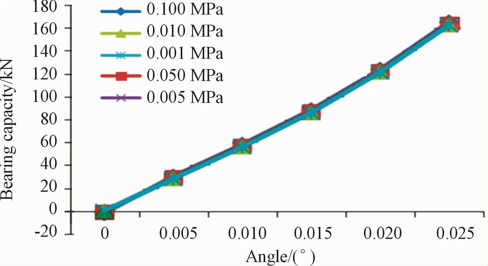
Fig.5 Oil film bearing capacity curve of the thrust block

Table 1 Cloud diagram of oil film pressure field of the thrust block
Fig.6 shows the characteristic curves of the oil film bearing capacity of the thrust disk.The curves in the figure are almost coincidental,and the change of oil film gap has little effect on the bearing capacity.The inlet pressure affects the oil film bearing capacity.With increasing inlet pressure,the oil film bearing capacity also increases.At the minimum boundary pressure of 0.005 MPa,the bearing capacity of the oil film decreases with increasing clearance of the thrust collar,and the minimum bearing capacity is0.727 2 kN.At the maximum boundary pressure of 0.200 MPa,the minimum oil film bearing capacity is 34.252 1 kN.The maximum bearing capacity in the figure is 34.404 7 kN,which is less than 75 kN.Thus,it can lubricate the thrust disk effectively and satisfy the oil film bearing capacity requirements when the rotor rotates.Table 2 shows the pressure cloud diagram of the oil film annulus under different pressures and oil film gaps.When the oil film gap of the thrust disk is large,the oil film pressure is unevenly distributed,and the pressure in the oil film inlet direction is high.When the oil film gap of the thrust disk is small,the oil film pressure is evenly distributed.

Fig.6 Thrust ring oil film bearing capacity curve

Table 2 Cloud diagram of oil film torus pressure field
7 Conclusions
Through CFD technology,the axial oil film bearing capacity of the dynamic pressure lubrication of the thrust bearing is simulated and calculated,and the following conclusions are drawn:
1)The inclination of the tile surface is 0.02°.The bearing capacity of the thrust block dynamic pressure oil film is greater than 1 210 kN,which satisfies the bearing capacity requirements of the tile.
2)At a thrust ring inlet boundary pressure of 0.200 MPa,the oil film bearing capacity is approximately 69 kN,which lubricates the thrust disk effectively and satisfies the oil film bearing capacity requirements when the rotor rotates.
This paper establishes a simulation model for the axial bearing capacity calculation of the thrust bearing dynamic pressure oil film.The simulation results provide theoretical guidance for the design of thrust bearings.
- 机床与液压的其它文章
- Analysis of cylindrical roller bearing with local damage based on multi-body dynamics
- Research of hydraulic gradient for large particle slurry in inclined pipeline
- Research on fault identification method of positive and negative fault subspace matrix
- Study on a LPs control algorithms in SCARrobot
- Research on mechanism of intelligent manufacturing equipment based on eye tracking control
- Path planning for obstacle avoidance of mobile robot based on optimized A*and DWA algorithm