
Analysis and experimental study on transmission accuracy characteristics of RV reducer
2021-01-20 05:35:58DongshengMAPengTANBingYAN
机床与液压 2020年24期
Dong-sheng MA,Peng TAN,Bing YAN
(1 Tianjin Vocational and Technical Normal University,Tianjin 300222,China)
(2 Tianjin Key Laboratory of high speed cutting and precision machining,Tianjin 300222,China)
(3Tianjin Polytechnic College,Tianjin 300400,China)
Abstract:The accuracy of RV reducer transmission is mainly affected by the transmission accuracy.Taking the high precision RV-80E reducer as the research object,aiming at its structural characteristics,the rigid-flexible coupling model of RV reducer is established by using ADAMSmulti-body dynamics simulation software,and the correctness of the model is verified.Meanwhile,the rigid-flexible coupling model is used to design several groups of simulation prototypes with different errors,and the influence of different error factors on the transmission accuracy of the whole machine is analyzed by simulation results.Through different error factors,it is concluded that the error combination of positive equidistance+negative offset or negative equidistance+positive offset can effectively reduce the influence of transmission error on the transmission accuracy of the whole machine,Finally,the main factors that affect the accuracy of the second stage transmission are obtained through the experimental test,which provides a certain theoretical basis for the production and manufacture of RV Reducer.
Key words:RV reducer,Rigid-flexible coupling,Transmission error,Transmission accuracy
1 Introduction
RV reducer is developed on the basis of traditional pin-cycloid planetary transmission.It not only overcomes the shortcomings of general pin-cycloid planetary transmission,but also has a series of advantages such as small size and smooth transmission.It is widely used in industrial robots,precision machine tools and other fields[1].With the continuous development of modern technology and the continuous improvement of processing and manufacturing technology,the requirement of transmission accuracy of RV reducer is becoming more and more important[2].It is of great theoretical and practical significance to improve the performance of RV reducer,reduce cost and form batch production.
In the rapid development of the electromechanical industry,many scholars have done a lot of analysis on the virtual prototype of RV reducer.However,the important parts of the reducer are seldom analyzed separately.Because of the large elastic deformation of the parts in the transmission process,the transmission accuracy is also greatly affected.V.Abousleiman and P.Velex of France carried out hybrid three-dimensional finite element analysis of planetary gear system,established solid model of planetary gear for dynamic analysis method,and analyzed the whole machine by ADAMS software,but only simply obtained several factors affecting transmission accuracy[3].Lu Jianwei and others have studied the reducer in the manipulator.Through the analysis of ADAMS simulation software,the law of the influence of the backlash on the transmission error of planetary gear transmission system has been obtained[4].Constant Safety provided a new idea to model the angular transmission error of reducer based on the multi-body dynamics simulation technology through the force analysis of crankshaft.The sensitivity of transmission accuracy of the system was obtained by numerical differentiation method[5].Li Chongning carried out modal analysis on the threedimensional model,obtained the natural frequencies and mode shapes of cycloidal wheel,and obtained the dynamic stress distribution function of cycloidal wheel by ADAMSsoftware[6].Hanlin Shan took 2K-V reducer as the research object,considered the processing error and installation error of each part comprehensively,established the dynamic transmission accuracy calculation model and solved it,but did not involve the gap and other factors[7].
In view of the above problems,this paper uses ADAMSmulti-body dynamics software to establish rigid-flexible coupling model of cycloid gear RV reducer,and analyses the influence of cycloid wheel workload,pin-tooth center circle radius and pin-tooth radius on the transmission accuracy of the reducer,The main factors affecting the transmission accuracy of the second stage are obtained through the experimental test,which provides a theoretical basis for the design and manufacture of RV reducer.
2 Establishment of rigid-flexible coupling model for multi-body dynamics of RV reducer
2.1 Establishment of three-dimensional model of RVreducer
ADAMS is a virtual prototype software which integrates modeling,solving,visualization technology and integration.But the process of building three-dimensional model is complex.So SolidWorks software is used to build three-dimensional solid model of RV reducer,and the format is saved as Parasolid(.x_t)format in MMKS,gravity direction is-Y.Then imported into ADAMS,the three-dimensional model under ADAMSenvironment is obtained.Its main parameters are shown in Table 1,and the entity model of the whole machine is shown in Fig.1.
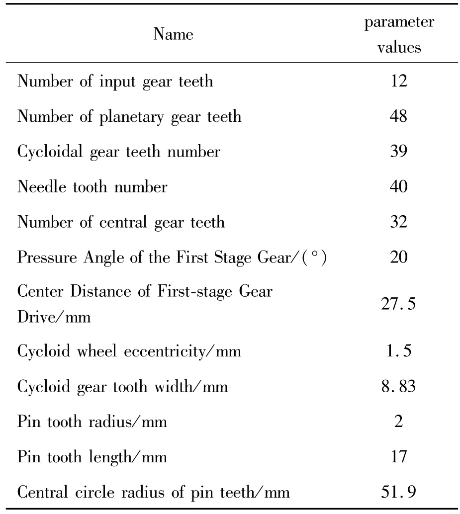
Table 1 Main parameters of RV reducer

Fig.1 Solid model of RV reducer
2.2 Model processing
After the model is imported,the simplified model is processed.Firstly,the pin teeth can rotate freely in the pin gear housing in the actual transmission process,and the transmission effect is not affected in the simulation.So the pin teeth and the pin gear housing can be fixed together,and then the material properties can be increased.The parts are set as“steel”.The elastic modulus is E=2.07×10¹¹Pa,the Poisson ratio is u=0.29,the density is P=7.801×10⁻⁶kg/mm3.Finally,the constraints are set for the reducer to achieve the correct results.The re-straint effect of RV reducer is shown in Table 2.

Table 2 Type of constraint pairs
2.3 Establishment of RV reducer flexible body
1)Defining unit types and material properties
Before the introduction of cycloidal wheel model,the motion pair of cycloidal wheel has been defined,and the former motion pair has been retained.The material is defined as GCr15,the modulus of elasticity is E=2.06×10¹¹Pa,Poisson’s ratio u=0.277,the density is Solid 20node186,and the meshing is done after the parameters are set.
2)Creating flexible body constraints
Based on Hertz contact theory,the contact force formula is as follows.

In the formula,K is the contact stiffness coefficient,C is the damping coefficient,m1,m2and m3are the stiffness index,the damping index and the indentation index,respectively.The stiffness index of the metal is 1.5 and the damping is 0.The flexible body of cycloid wheel is established as shown in Fig.2 and the rigid-flexible coupling model with additional constraints is shown in Fig.3.

Fig.2 Flexible body model of cycloid wheel
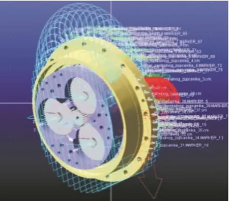
Fig.3 Rigid-flexible coupling model with constraints
3 Simulation and verification of rigidflexible coupling model
3.1 Characteristic analysis of RV reducer
Fig.4 is the transmission structure sketch of RV-80E reducer.The transmission mechanism of RV reducer is divided into two stages.The first stage is the deceleration mechanism that meshes the central wheel with the planetary wheel,and the second stage is the deceleration mechanism that meshes the cycloid wheel with the pin teeth.
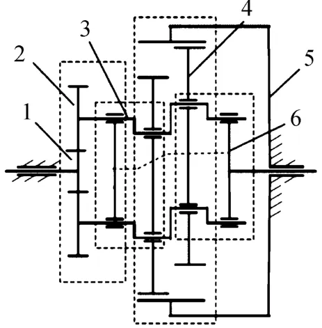
Fig.4 The transmission sketch of RV reducer

In the formula,ZP,ZSis the number of center wheel and input shaft teeth respectively.
The speed ofωp,ωs,ωothe center wheel,the input shaft and the planetary frame respectively.
Assuming that the crankshaft is fixed,the second stage transmission ratio.cycloidal pinwheel transmis-
According to the transformation mechanism method,assuming that when the planetary frame is fixed,the first transmission ratio.the transmission ratio of the input shaft to the planetary wheel is assumed:sion ratio:

In the formula,ZP,ZSis the number of teeth of needle wheel and cycloid wheel is respectively.ωc,ωris Cycloid wheel and needle wheel speed respectively.
The rotation speed of planetary frame is the same as that of cycloidal gear.

When the needle wheel is fixed

The speed ratio of the planetary gear to the input shaft can be obtained simultaneously.

3.2 Model simulation and verification
ADAMSsoftware is used to simulate multi-body dynamics.Set simulation parameters:simulation time is 10 seconds,simulation step is 0.01.Use“PostProcessor”in ADAMSto view the simulation results.The output angular velocities of input shaft,crank shaft and output disk are shown in Fig.5,Fig.6,Fig.7,and the relative errors of each part are shown in Table 3.
Table 3 shows that the relative error of the main parts is less than 1%,which proves that the model is correct and can be used for further analysis.

Fig.5 Angular velocity curve of input axis

Fig.6 Angular velocity curve of crankshaft

Fig.7 Output disk angular velocity curve

Table 3 Comparison of simulation and theoretical values of angular velocity at all levels
4 Effect of error on transmission accuracy of RV reducer
In the actual transmission process,there will inevitably be a gap between the parts.In order to avoid the phenomenon of the parts jamming each other in the transmission process,it is necessary to set aside a certain gap,which will inevitably affect the transmission accuracy of the reducer.In order to facilitate comparison,the error factors such as the displacement of cycloidal wheel,the equal distance of cycloidal wheel and the radius of pin and tooth affect the transmission accuracy.

Table 4 Error value table

Continued Table

Fig.8 Prototype transmission error curve
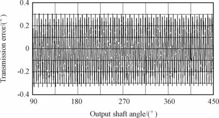
Fig.9 Model 1 transmission error curve

Fig.12 Model 4 transmission error curve

Table 5 Virtual prototype error curve data statistics results
Compared with the prototype,the first four models increase 6.05%,5.40%,3.59%,1.47%,respectively.When the error is the same,reducing the radius of needle teeth will bring the greatest error,and the distance training will bring the smallest error.put shaft was measured.The test results are shown in Figs.21-26.

Fig.10 Model 2 transmission error curve
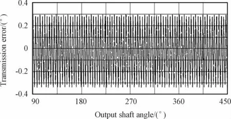
Fig.11 Model 3 transmission error curve
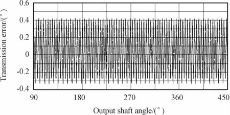
Fig.13 Model 5 transmission error curve

Fig.14 Model 6 transmission error curve

Fig.15 Model 7 transmission error curve
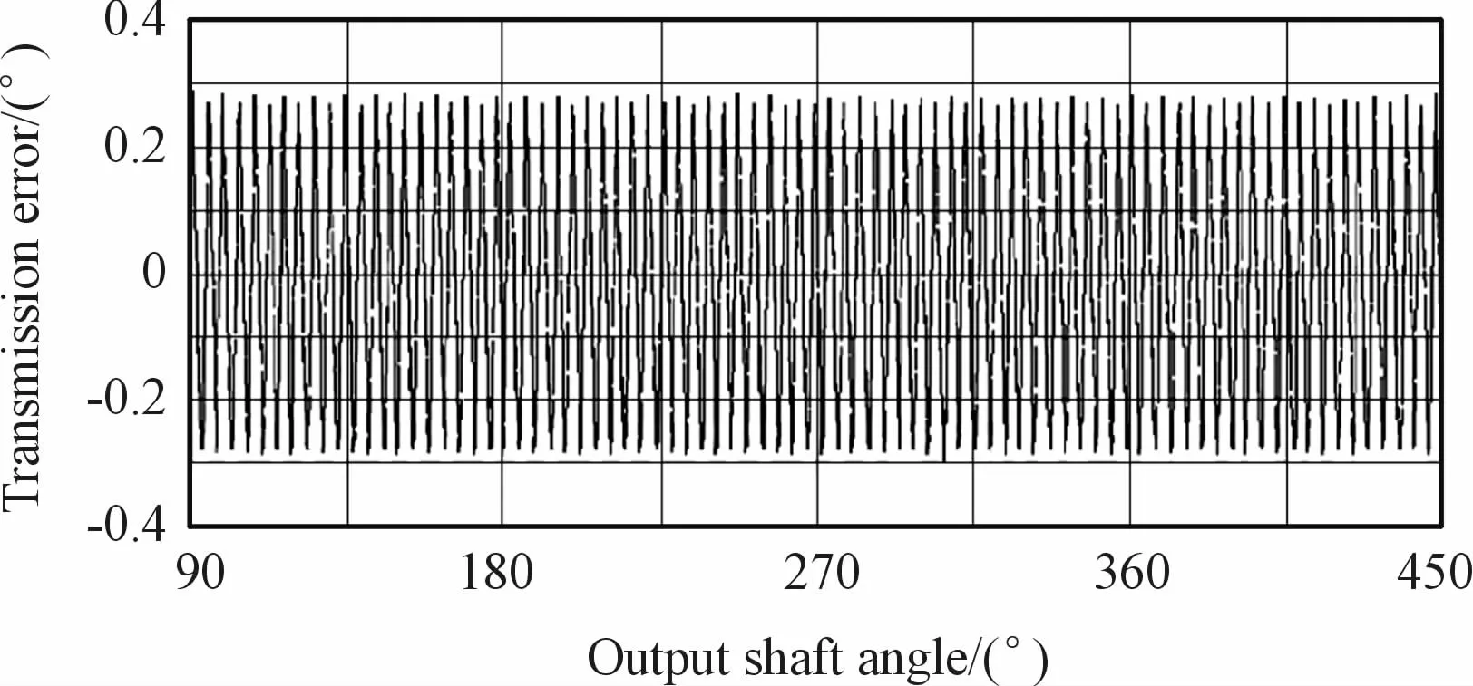
Fig.16 Model 8 transmission error curve

Fig.17 RV Reducer experimental platform
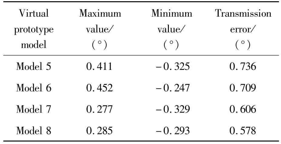
Table 6 Virtual prototype error curve data statistics results
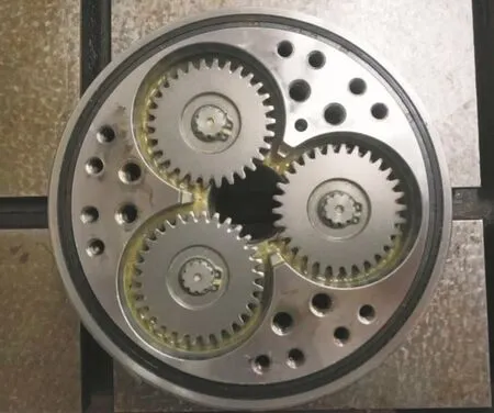
Fig.18 Japan Sumitomo RV Reducer experimental prototype
The fifth and sixth models are increased by 20.3%and 15.8%respectively compared with the prototype,which leads to further widening of the gap between the parts,so this situation should be avoided.Seventh,the eight models are reduced by 0.98%and 5.56%respectively compared with the prototype,and the effects of transmission error can be reduced by using positive equidistance+negative shift or negative equidistance+positive shift.
5 Experimental test analysis
Under the same experimental conditions,three different RV reducers from abroad and China are selected for transmission error test.The test bench and reducer are shown in Figs.17-20.In the experimental test,the forward and reverse transmission error curves of three RV reducers were measured,and the change value of transmission error in the process of two rotation of out-

Fig.19 Zhejiang Hengfengtai RV Reducer experimental prototype

Fig.20 Kunming Dongsheng RV Reducer experimental prototype

Fig.21 Forward rotation transmission error of RV Reducer in Sumitomo Japan
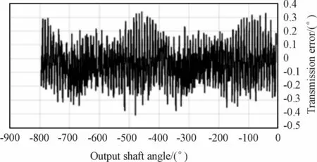
Fig.22 Reverse transmission error of RV Reducer in Sumitomo Japan

Fig.23 Forward rotation transmission error of Zhejiang Hengfengtai RV Reducer

Fig.24 Reverse transmission error of Zhejiang Hengfengtai RV Reducer

Fig.25 Forward rotation transmission error of Kunming Dongsheng RV Reducer
From Fig.21 and Fig.22,it can be concluded that the maximum error values of the forward and reverse rotation of the Sumitomo Japan RV Reducer are 0.857 7′and 0.734 2′respectively,which does not exceed 1′,indicating that the transmission accuracy of the reducer meets the requirements.As can be seen from Figs.23-24,the maximum error values of forward and reverse rotation of the Zhejiang Hengfengtai RV Reducer are 2.173 6′and 2.1118′respectively.From Figs.25-26,the maximum error values of forward and reverse rotation of the Kunming Dongsheng RV Reducer are 2.122 6′and 2.126 1′respectively.Compared with foreign RV Reducer experimental prototype,the forward rotation of the two domestic RV reducers increases by 60.54%and 59.59%,and the reverse rotation increases by 65.23%and 65.46%respectively It can be concluded that the transmission error of RV Reducer in China is large.
The above experiment is to measure the transmission error curve of the three RV reducers.From the curve,we don’t know which part of the RV Reducer has larger transmission error and which part has smaller transmission error.However,from the simulation figures made in the previous chapters,the second stage transmission error is larger than that of the first stage.The following is mainly about the contact part between the second stage cycloid wheel and the needle gear Simulation analysis is carried out.
In fact,there are many kinds of transmission errors of RV Reducer,so it is difficult to test them all by experiment.After selecting the transmission error data of RV Reducer,the spectrum analysis is carried out,and the spectrum diagram obtained is compared with the experimental figure to verify the consistency of theoretical results and experimental results,as shown in Table 7.

Table 7 A group of values of RV Reducer transmission error setting
According to Fig.27,the maximum transmission error of RV Reducer is 0.413′,less than 1′,which is consistent with the transmission error theory.
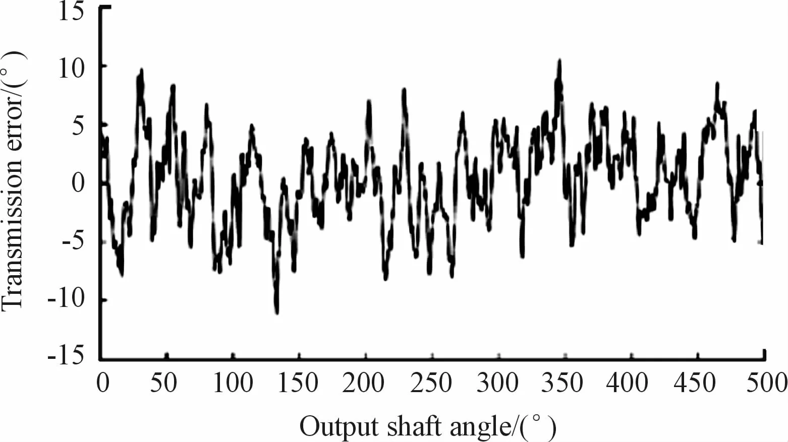
Fig.27 Simulation results of transmission error
It can be seen from Fig.28 that when the RV Reducer output plate rotates for one cycle,the cycloid wheel also rotates for one cycle.If there is error in cycloid wheel,the influence will change regularly with one cycle,so the error of cycloid wheel will be reflected in the frequency doubling.In the same way,when the output shaft rotates one circle,the crank shaft rotates for 40 turns.The error on the crank shaft produces a transmission error fluctuation with the same change rule in the process of the output shaft rotating for one circle.Therefore,the error at 40 times and the integral multiple of 40 times frequency has a certain relationship with the crank shaft.

Fig.28 Spectrum of RV-80E transmission error
6 Conclusion
1)The three-dimensional model of RV reducer is built by SolidWorks and imported into ADAMS.The finite element model of cycloidal wheel is established by using multi-flexible body dynamics technology.The rigid-flexible coupling model is obtained.The angular velocity of each main component is obtained by simulation,which is consistent with its theoretical value,and the correctness of the model is proved.
2)The error factors that lead to the clearance between the needle teeth and cycloidal gear have the greatest influence on the transmission accuracy,which is to reduce the radius of the needle teeth,to increase the radius of the distribution circle of the needle teeth,and to minimize the distance training of the cycloidal gear.
3)According to the transmission error table,it can be found that the single transmission error factor is not the superposition of the combined transmission error.When the positive offset+negative offset or positive offset+negative offset is adopted,the transmission error can be reduced.
4)The transmission error experimental platform of RV Reducer is built,and the transmission error test experiments of three foreign and domestic reducers are carried out,and the transmission error test curves of forward and reverse rotation are obtained.Through the analysis of the test results,there is a big gap between the transmission accuracy of domestic RV Reducer and the advanced level of foreign countries.By analyzing the frequency spectrum of the second stage cycloid wheel of RV Reducer,the reason of excessive trans-mission error of the second stage is preliminarily judged.
- 机床与液压的其它文章
- Analysis of cylindrical roller bearing with local damage based on multi-body dynamics
- Research of hydraulic gradient for large particle slurry in inclined pipeline
- Research on fault identification method of positive and negative fault subspace matrix
- Study on a LPs control algorithms in SCARrobot
- Research on mechanism of intelligent manufacturing equipment based on eye tracking control
- Path planning for obstacle avoidance of mobile robot based on optimized A*and DWA algorithm