
Design of ultrasonic test and control system for truss robot
2021-01-20 05:35:56BeitaoGUOYafenZHANGYanruiLI
机床与液压 2020年24期
Bei-tao GUO,Ya-fen ZHANG,Yan-rui LI
(Shenyang University of Chemical Technology,Shenyang 110142,China)
Abstract:In order to detect the internal defects of the workpiece more accurately,an automated ultrasonic test system for truss robot is proposed,and the power spectrum analysis technology is used to analyze the defect echo signal.The control system was developed and the ultrasonic testing software program was compiled,the control system composed of industrial computer and PLCcan control the truss robot to realize the three-dimensional movement,while driving the ultrasonic probe can test the inner defects automatically.Compared with traditional ultrasonic testing methods,the power spectrum analysis method that analyze the ultrasonic echo signal of the inner defects can obtain obvious different defect characteristics,and identify small internal defects more accurately.In consequently,this test and control system for the truss robot improve the accuracy and efficiency of the ultrasonic test.
Key words:Ultrasonic detection,Truss robot,PLC,Power spectrum analysis
With the rapid development of modern industrial,the shape of the inner surface of the rotating workpiece is becoming more and more complicated,which puts forward higher requirements for the automatic detection of internal defects of workpieces with different diameters and lengths.At this stage,many domestic university and company study using ultrasonic test technology to analyze and detect inner defects in the workpieces[1-3].However,the echo signal of ultrasonic testing is mixed with various interference signals,which made distinguish defects more difficult.The defect signal needs to be further analyzed and processed to obtain more useful information.
In order to solve the above problems,an ultrasonic test and control system based on truss robot has been developed,and the power spectrum analysis is used to distinguish defects of different diameter workpieces more precisely.Practice shows that the system improves the automation and accuracy of ultrasonic testing.
1 Working principle of the system
The structure diagram of the ultrasonic inspection system of the truss robot is shown in Fig.1.The X-axis and Y-axis of truss robots are driven by stepper motors,and the Z-axis is driven by servo motors[4].The ultrasonic prob is equipped on the end of Z-axis.When the workpiece is sent to the specified position,the workpiece can be driven by a roller at the speed required for detection.The different speed of the roller is controlled by the frequency converter which is driven by PLC.The truss robots drive the ultrasonic probto detect along the spiral track.After the flaw detection is completed,each unit of the truss robot returns to its original position,and the workpiece is sent out by the feeding device.

Fig.1 Truss robot ultrasonic testing system
2 Principle of power spectrum analysis
For the defects size of workpieces are different,the ultrasonic echo signal is different.The differences between the ultrasonic echo signals cannot be fully shown in time domain than in frequency domain,so the power spectrum is used to analyze the energy characteristics of the random signal,and the useful signal submerged in the noise is extracted in the frequency domain based on the limited data,so as to achieve the purpose of analyzing the defect characteristics of the workpiece[5].
For a random process x(t),define its autocorrelation function as Rx=(t,s)=E(x(t)x(s)),the definition of power spectrum estimation based on autocorrelation is the Fourier transform of the autocorrelation function,that
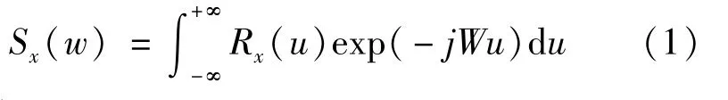
Where Sx(w)represents the power spectrum.
Used represent the signal x(n)power spectrum estimation calculated by Welch algorithm,namely
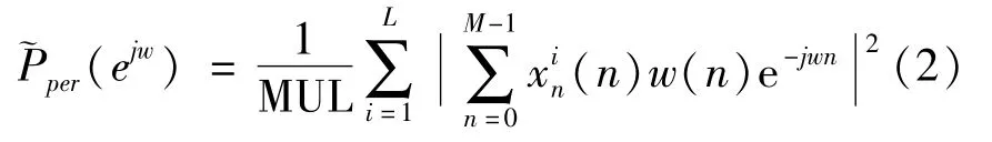
The length of x(n)is N,which is divided into L segments,each segment has M data,w(n)is the window function,theis normalization factor[6-8].
3 Design of control system hardware and software
3.1 Hardware structure design of control system
The hardware of the control system consists of controllable programmer PLC,PLC extension module,frequency converter,motor driver,solenoid valve,etc.The PLC receives the instruction from the host computer and the feedback signal from the sensor,and drives the inverter and motor driver according to the corresponding program and parameters[9].The X and Y movement of truss robot are realized by stepping motor driving synchronous belt,and the Z axis movement is realized by servo motor driving ball screw.The system hardware diagram is shown as in Fig.2.

Fig.2 System hardware diagram
The required speed of the workpieces for the test bench is obtained by PLC controling the frequency converter and the motor.The speed regulation is achieved by Siemens V20 inverter,the voltage signal of the analog is used as the input of the inverter,and then the frequency is adjusted to control the speed of motor,therefore,the speed of the workpieces is obtained[10].The electrical diagram of the inverter,PLC and motor is shown in Fig.3.
3.2 System software design
Compiling the control system software,different parameters are preset according to the size of different workpieces and input them into the program.At first,the initialization is in progress,which include the input signals of the position proximity switch,the movement status of the roller motor,etc.Then alarge num-ber of pulses are sent to the motorsby PLCin the truss robot system to manipulate the motors to locate the probe[11-12].After the probe is positioned the flaw detectingbegin.Finally,while the detecting work is completed,the detection signal is collected and data processing are carried out by the industrial computer.The PLC control flow is shown in Fig.4.
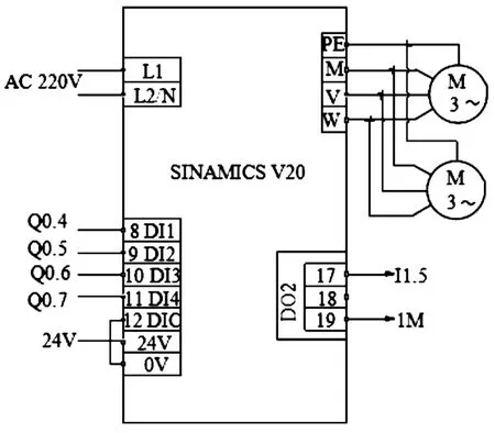
Fig.3 Wiring diagram of inverter V20
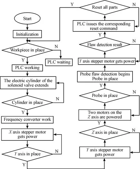
Fig.4 PLC control flow chart
4 Automated ultrasonic testing experiment
The mechanical structure and control system of truss robot with ultrasonic detection system are designed.After the hardware selection and software program design of the PLCcontrol system,combined with the ultrasonic test instrument,the waveform analysis is performed.The system can realize the automatic ultrasonic inspection of the workpiece.The physical map of the assembled equipment is shown in Fig.5.

Fig.5 Assembly drawing of ultrasonic testing equipment
Fig.6 is a waveform diagram of automatic ultrasonic testing for aluminum alloy with different hole diameters displayed on the screen of an industrial computer.As can be seen from Fig.6,the difference of the ultrasonic echo signals of inner defects between(a)and(b)is very small in time domain.
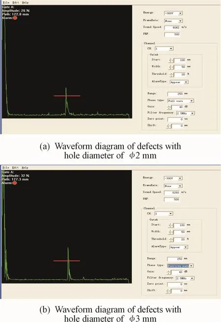
Fig.6 Waveform of crack defects
The ultrasonic detector is used to collect defect data for holes with different diameters of 2 mm and 3 mm in Fig.6.Totally 500 sets of data are collected for two types of defects.According the collected data and noise signal,the waveform curves are drawn as shown in Fig.7.
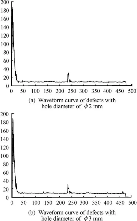
Fig.7 Waveform curve of defects
Used the welch algorithm inMATLAB software to simulation analysis the power spectrum of the ultrasonic echo signalsfor inner defectsare shown in Fig.8.It can be seen from Fig.8 that the amplitude of the3 mm defect echo is greater than that of 2 mm.

Fig.8 Power spectrum of the hole
It can be observed that the ultrasonic echo signals of inner defects are obvious in frequency domain.In the power spectrum figure,the larger diameter of the defect hole,the higher the peak of the ultrasonic echo signals of inner defect,the greater the amplitude of the power spectrum corresponding to the size of the inner defect.The comparison between Fig.7 and Fig.8 shows that the power spectrum method is more accurate.
5 Conclusion
The ultrasonic test system for the truss robot was researched in this article,and the PLC control system and the mechanical system of the truss robot were combined to realize the automatic ultrasonic test.In the ultrasonic defect signal analysis of workpiece,compared with the traditional ultrasonic detection method,the power spectrum analysis method can obtain obvious defect characteristics.The practical application shows that the ultrasonic test and control system for truss robot improves the detection accuracy and efficiency.
- 机床与液压的其它文章
- Analysis of cylindrical roller bearing with local damage based on multi-body dynamics
- Research of hydraulic gradient for large particle slurry in inclined pipeline
- Research on fault identification method of positive and negative fault subspace matrix
- Study on a LPs control algorithms in SCARrobot
- Research on mechanism of intelligent manufacturing equipment based on eye tracking control
- Path planning for obstacle avoidance of mobile robot based on optimized A*and DWA algorithm