Optimal UAV deployment in downlink non-orthogonal multiple access system: a two-user case
Liu Tingting (刘婷婷), Wang Yuntian, Wang Junhua, Pan Ziyu, Yu Yu
(*School of Information and Communication Engineering, Nanjing Institute of Technology, Nanjing 211167, P.R.China)(**Nanjing University of Science and Technology, Nanjing 210094, P.R.China)(***Nanjing University of Aeronautics and Astronautics, Nanjing 210024, P.R.China)
Abstract
Key words: unmanned aerial vehicle (UAV) deployment, downlink non-orthogonal multiple access (NOMA), two-user case
0 Introduction
Recently, non-orthogonal multiple access (NOMA), which is recognized with high spectrum efficiency, has attracted great attention as a crucial technique for 5G networks[1-3]. Employing the NOMA scheme, users can be multiplexed at different power levels, while users can simultaneously access other resources, such as frequency, time or code resources. At the receiver side, users utilize a successive interference cancellation (SIC) to extract their corresponding signals[4].
Although, NOMA can achieve superior performance, edge users in a network still suffer from service quality degradation. There are still many challenges to advance NOMA in 5G networks. For these reasons, because of the flexibility for deployment, unmanned aerial vehicles (UAVs) or drones with advanced sensors and transceivers have attracted great attentions in communication community. Specifically, UAVs can exploit the benefits of line-of-sight (LoS) air-to-ground communication channels to provide enhanced communication services, such as mobile coverage[5,6], mobile relaying[7,8]and mobile data collection[9-11], etc.
Existing researches on UAVs can be divided into 2 directions, i.e., static-UAV and mobile-UAV directions[12]. The combination researches on the mobile-UAV and NOMA scheme focus on the UAV trajectory design and communication scheduling. In Ref.[13], the authors optimize the trajectory of UAV and the precoding vectors of NOMA base station (BS) in order to maximize the sum rate for UAV-assisted NOMA networks.
In order to enhance the service quality for multiple users, the combination researches on the static-UAV NOMA scenario are also promising. In Ref.[14], the authors derive the outage probability of UAV connected users and device-to-device (D2D) underlaying NOMA static-UAV assisted networks, and provide a sub-optimal power control solution. Besides the outage probability, UAV’s placement problem in a static-UAV NOMA scenario is also very important, especially for enhancing the service performance of edge users. In Ref.[15], the authors investigate the UAV placement and power allocation problem. The problem is separated into 2 sub-problems. The optimal location of UAV is obtained by minimizing the sum path loss, and the optimal power allocation is then derived.
Different from the existing work, this paper investigates the optimal UAV deployment problem in downlink NOMA system from the perspective of maximizing user’s sum rate. The main contributions of this paper are listed as follows.
(1) A UAV-enabled NOMA system, where a UAV is deployed as an aerial base station, which transmits data to two ground users, is considered in this paper.
(2) In order to maximize two users’ achievable sum rate, an optimal UAV placement problem is therefore constructed. Since it is intractable to solve this problem, a feasible solution region is first reduced by a theorem. Then, an analytical solution of the proposed problem under a certain situation is discussed.
(3) Finally, an algorithm is proposed to solve the optimization problem in a general manner.
(4) Extensive numerical results are presented to demonstrate effectiveness of the proposed algorithm, and its advantages over the benchmarks from the perspective of maximizing users’ sum rate.
This paper is organized as follows. System model and problem formation are presented in Section 1. The proposed algorithm is elaborated in Section 2. Extensive numerical results are depicted in Section 3, and finally conclusions are drawn in Section 4.
1 System model and problem formulation
As shown in Fig.1, a UAV-enabled NOMA system, where a UAV is deployed as an aerial base station to transmit data to two ground users, is considered in this paper. Without loss of generality, a 3-D Cartesian coordinate system is considered with two ground users, i.e., user 1 and user 2 in Fig.1, located atw1=[L, 0, 0]Tandw2=[-L, 0, 0]T, respectively. It is assumed that the UAV is deployed atq=[x,y,H]T, whereHis the fixed flight altitude of the UAV. For simplicity, it is assumed that all the nodes in the network are equipped with a single antenna, and the communication links from the UAV to the ground users are line-of-sight (LoS) dominated. It is also assumed that the Doppler effect caused by the UAV motion is perfectly compensated at the ground users. Thus, the channel coefficienthifrom the UAV to useri, {i=1,2}, can be expressed as
(1)
where,λ0is the channel gain at the reference distanced0=1 m, anddi=|q-wi| denotes the distance from the UAV to useri.
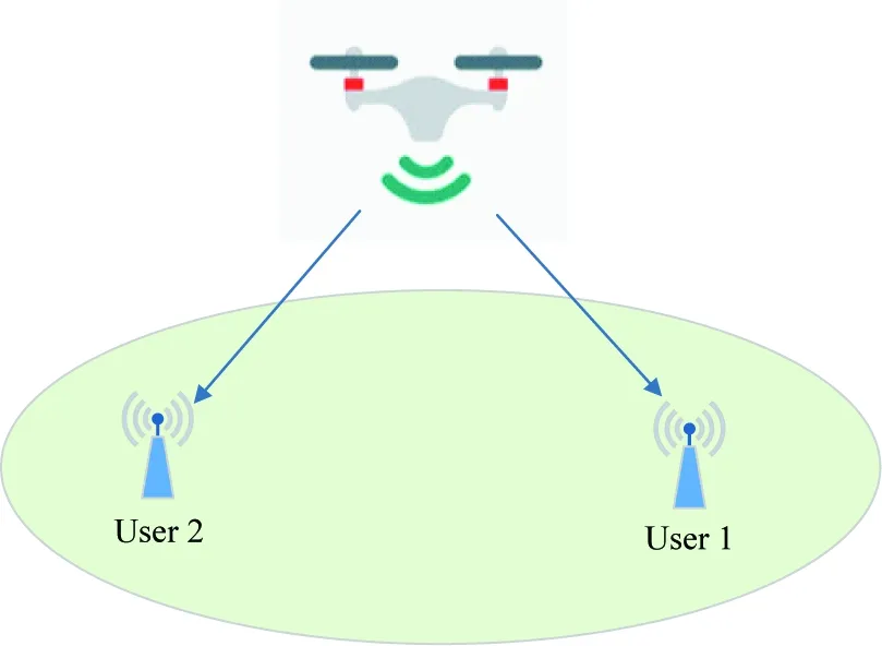
Fig.1 UAV-enabled NOMA network with two users
The UAV transmits the superposition signal to the two ground users simultaneously, which can be expressed as
(2)
wheres1ands2denote the signal intended for user 1 and user 2, respectively.P1andP2are the corresponding transmission power for user 1 and user 2, respectively. The transmission power must comply with the following 2 conditions.
P1+P2≤Pmax
(3a)
Pi≥0,i=1,2
(3b)
wherePmaxdenotes the maximum transmission power of the UAV. Thus, the received signal at useriis
i=1,2 (4)

According to NOMA principle, SIC is utilized at the receivers. Because of symmetry, only the case withx≥0 is considered in the following discussions. Also it is assumed that user 1 is treated as a stronger user, while user 2 is treated as a poorer user. Thus, the signal intended for user 2 is first decoded, and then for user 1. As a result, the achievable rate from the UAV to user 1 and user 2 can be expressed as
R1=log2(1+P1λ1)
(5a)
and
(5b)
In order to maximize users’ achievable sum rate, an optimization problem can be formulated as
(6a)
s.t., Eq.(3a), Eq.(3b)
(6b)
Ri≥r*,i=1,2
(6c)
whereP={P1,P2}, andr*denotes the achievable rate threshold. Constraint Eq.(6c) can be used to guarantee user’s quality of service (QoS). It can be seen that problem Eq.(6) is non-convex. Because the objective function Eq.(6a) is non-concave, and the constraint Eq.(6c) is non-convex with respect toqandP, respectively. Thus, it is challenging to solve problem Eq.(6) by the conventional optimization methods.
2 Proposed algorithm for problem Eq.(6)
In this section, the solution of problem Eq.(6) will be provided. First, the problem is simplified. Then, an analytical solution of the simplified problem under a certain situation will be presented. At last, a generalized algorithm is proposed to obtain the optimal solution of problem Eq.(6).
2.1 Problem simplification
In order to simplify problem Eq.(6), Theorem 1 is provided as follows.
Theorem1To maximize users’ summation of the achievable rates, the UAV should be deployed above the line segment between the two users.
ProofTheorem 1 is demonstrated by contradiction. This work first assumes that the optimal UAV deployment location is given byq0=[x0,y0,H]T, wherey0≠0. That is to say, the UAV is not located over the line through the two users. The UAV transmits with the maximum transmission power at the optimal solution[16], i.e.,
P1+P2=Pmax
近期疗效评价[3]:完全缓解(CR)指肺癌病灶完全消失,无新起病灶,且时间持续1个月以上;部分缓解(PR)指肺癌病灶面积缩小程度>50%以上,无新起病灶;病情稳定(SD)指肺癌病灶面积缩小程度≤50%,增大程度≤25%;病情进展(PD)指肺癌病灶面积增大程度>25%,或有新起病灶。疾病控制率(DCR)为(CR+PR+SD)/总例数。
(7)
Then, the achievable rates of the two users at the optimal solution can be expressed as
(8a)
and

Conditions Eqs(8a) and (8b) are satisfied because of the QoS constraints. Given another UAV’s location atq1=[x0, 0,H]T, that is to say, the UAV’s location is over the line of the two users, i.e.,
(9)
(10a)
(10b)
where condition Eq.(6c) in Eq.(10b) holds, since ifα>β, the functiong(x)=log2(1+αx)-log2(1+βx) is monotonically increasing with respect to the variablex. Therefore, the sum rate atq1=[x0, 0,H]Tis larger than that atq0=[x0,y0,H]T, ∀y0≠0. This conclusion contradicts the assumption thatq0is the optimal location that can get the maximum sum rate. Therefore, it can be concluded that a higher sum rate can be achieved by deploying the UAV over the line through the two users compared to other locations.
Next, proofs on that the optimal UAV location should over the line segment between the two users are provided. Given a locationq2=[x, 0,H]T, ifx>L, i.e., over the extension line of the two users, the UAV can be always deployed atq3=[L-(x-L), 0,H]Twhich is a symmetrical location respective to user 1, and obtain a larger sum rate compared to that atq2. As a result, in order to maximize the sum rate of the two users, the UAV should be deployed above the line segment between the two users, i.e., 0≤x≤L. This completes the proof.
Based on Theorem 1, the UAV’s location can be simplified asq=[x, 0,H]T. According to the conclusion drawn in Ref.[16], in order to obtain the maximum sum rate, the optimal power allocation strategy can be represented as
(11a)
and
(11b)
(12)
and
R2=r*
(13)
respectively. Observing Eqs(12) and (13), it can be found that by employing the power allocation strategy, the rate of user 2, i,e, the poorer user, is equal to the rate threshold and irrelevant to the UAV’s location. The rate of user 1 can be further enhanced by varying the UAV’s locationx.
Thus, problem Eq.(6) can be simplified as
maxxf(x)
(14a)
0≤x≤L
(14b)
where

(15)
In order to assure rate of the user 1 is larger than the rate thresholdr*, the following remark is provided.
Remark1If the maximum value off(x) is greater than 2r*(2r*-1), problem Eq.(6) is feasible. Otherwise, problem Eq.(6) is infeasible and a smaller value ofr*should be considered.
When problem Eq.(6) is feasible, the following remark is provided.
Remark2The sum rate of the two users, i.e.,R1+R2, is decreasing asr*increases.
ProofThe first-order derivation ofR1+R2is as follows.
(16)
Since 0≤x≤L, thusλ1>λ2holds. Moreover, based on Remark 1, Eq.(16)<0. Thus,R1+R2is an decreasing function respective tor*.
Note that problem Eq.(14) is a univariate optimization problem which may be solved by derivation.
2.2 The analytical solution to problem Eq.(14)
The first-order derivation off(x) is given by
(17)
2Lx2-Ax+AL-2L(H2+L2)=0
(18)
Eq.(18) is a quadratic function withΔ=A2-8AL2+16L2(H2+L2). IfΔ≥0, then the stationary points off′(x) are given by
(19)
In the following, it should be determined whether the 2 stationary points are in the interval, and then obtain the optimalx(denoted byx*). Based on the above derivations, the UAV deployment strategy is concluded in Algorithm 1.

Algorithm 1Proposed UAV deployment strategy1.IfΔ≥0then2.Case 1Ifx1Solu∈(0, L), x2Solu∈(0, L),thenx*=argmax{f(0), f(x1Solu), f(x2Solu), f(L)}3.Case 2Ifx1Solu∈(0, L), x2Solu∉(0, L),thenx*=argmax{f(0), f(x1Solu), f(L)}4.Case 3Ifx1Solu∉(0, L), x2Solu∈(0, L),thenx*=argmax{f(0), f(x2Solu), f(L)}5.Case 4Ifx1Solu∉(0, L), x2Solu∉(0,L),thenx*=argmax{f(0), f(L)}6.Elsef(x) is a monotonic increasing function with respect to x. Therefore, x*=L7.End if8.If f(x*)≥2r*(2r*-1)thenx* is determined.9.Else10.Reconsiderr*.11.End if

Note that the proposed algorithm is applicable in a two-user scenario. For the multi-user scenario, the optimal UAV deployment problem is complex, and it probably cannot get a closed-form solution. The UAV deployment problem will be investigated in a multi-user scenario in the future work.
3 Numerical results
In this section, numerical results are presented to demonstrate effectiveness of the proposed UAV deployment scheme (denoted as the DP scheme). The simulation parameters are set asL=500 m,Pmax=1 W,H=100 m, andγ0=106.
Fig.2 plots the optimal UAV deployment location using the proposed DP scheme whenr*varies. Linear search curves are also plotted to verify the correctness of the analytical solution. It is clearly presented that the linear search results are well matched with the analytical results. It can also be observed that the optimal UAV deployment location moves away from user 1 asr*increases. The reason is that asr*increases, user 2 needs more transmission power to satisfy the QoS constraint, and, therefore, the UAV tries to strike a balance between the transmission power of the two users. This phenomenon can be also verified by Remark 2.
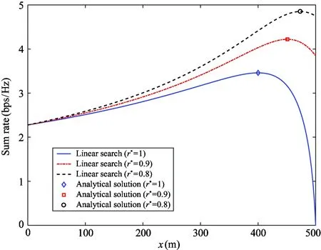
Fig.2 Optimal deployment location for DP scheme versus r*.
For comparison, the following 2 schemes are considered as benchmarks.
(1)FDMAA UAV-enabled FDMA system, which is different from NOMA system in this paper, also can demonstrate that the optimal UAV deployment location is over the line segment between the two users. Given a UAV’s location and the power constraint, in order to maximize the sum rate, the optimal power allocation based on the water-filling scheme is first determined. Then, the location is varied to find the optimal solution that can maximize the sum rate. This scheme can be used to demonstrate advantages of the NOMA system.
(2)PoweroptimizationwithoutUAVdeployment(POWD)A UAV-enabled NOMA system, where the UAV’s location is fixed over user 1 and the optimal transmission power is obtained with the same manner used in our scheme. POWD scheme is used to demonstrate the advantages of the DP scheme.
Fig.3 plots the variation of sum rate for the FDMA scheme versus differentr*. A curve of NOMA whenr*=0.8 is also plotted for comparison. A portion of the FDMA scheme curves are not drawn, due to the reason that the QoS constraint is not satisfied. Moreover, the NOMA scheme can always achieve a higher sum rate compared to the FDMA scheme. That is because the NOMA scheme is known to have a higher spectrum efficiency compared to the FDMA scheme.
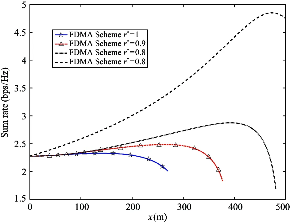
Fig.3 Optimal deployment location for FDMA scheme versus r*
Fig.4 compares the sum rate of the 3 different schemes versus differentr*. It can be noted that the sum rate of the proposed DP scheme decreases asr*increases. This phenomenon is consistent with Remark 2. Also, it can be observed that the proposed DP scheme outperforms the FDMA scheme and the POWD scheme from the perspective of sum rate. The proposed DP scheme can achieve a higher sum rate compared to the FDMA scheme, because of the employed NOMA manner. The proposed DP scheme can obtain a higher sum rate compared to the POWD scheme, because of the optimal UAV location deployment. Moreover, it should be pointed out that whenr*=1 bps/Hz, the POWD scheme cannot satisfy the QoS constraint, and therefore the sum rate drops to zero. Therefore, the conclusion can be drawn that by designing the optimal UAV’s deployment location, not only the sum rate can be enhanced, the QoS of each user can also be assured.
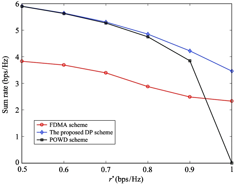
Fig.4 Sum rate versus r*
4 Conclusion
In this paper, the optimal UAV’s deployment problem is studied in a two-user case. In order to maximize users’ sum rate, an optimization problem is first constructed, considering the QoS and power constraints. Then, a feasible solution region of the problem is reduced to a line segment between the two users. This conclusion can help us further reduce the original optimization problem to a simplified one. Next, by giving a UAV’s location and utilizing the optimal power allocation strategy which is relevant to the UAV’s location, the optimization problem is reduced to a univariate problem. The analytical solution to the simplified problem under a certain situation is provided, and moreover, a generalized algorithm is proposed to further determine the optimal UAV’s location. Simulation results are presented to demonstrate effectiveness of the proposed DP scheme in maximizing the sum rate and its advantages over the FDMA and POWD schemes.
 High Technology Letters2020年4期
- High Technology Letters的其它文章
- Experimental study on vibration suppression in a rotor system under base excitation using an integral squeeze film damper
- Grouping pilot allocation scheme based on matching algorithm in massive MIMO system
- Fraudulent phone call recognition method based on convolutional neural network
- Behavior recognition based on the fusion of 3D-BN-VGG and LSTM network
- Dynamic A* path finding algorithm and 3D lidar based obstacle avoidance strategy for autonomous vehicles
- An effective indoor radio map construction scheme based on crowdsourced samples
