Defects and Optical Property of Single-crystal Sapphire Fibers Grown by Edge-defined Film-fed Growth Method
WANG Donghai, HOU Wentao, LI Na, LI Dongzhen, XU Xiaodong, XU Jun, WANG Qingguo, TANG Huili
Defects and Optical Property of Single-crystal Sapphire Fibers Grown by Edge-defined Film-fed Growth Method
WANG Donghai1, HOU Wentao1, LI Na1, LI Dongzhen2, XU Xiaodong2, XU Jun1, WANG Qingguo1, TANG Huili1
(1. School of Physics Science and Engineering, Tongji University, Shanghai 200092, China; 2. School of Physics Electronic Engineering, Jiangsu Normal University, Xuzhou 221116, China)
Single-crystal sapphire fibers with diameter of 400-1000 µm and length of 500 mm were successfully grown by the edge-defined film-fed growth (EFG) method. The cross section is roughly circular without noticeable faceting on the lateral surface of the fiber. The diameter variation was within 40 µm in the whole fiber. Crystal defects such as micro-bubbles, inclusions and growth stripes were observed and analyzed. Most micro bubbles in the crystal are spherical and exist on the periphery of the fiber. A small amount of Mo inclusions were observed on the periphery of the fiber. The new dies produce greater number of Mo inclusions at the first several uses, and Mo inclusions decrease after several uses. Size and distribution of micro-bubbles in sapphire fiber have been studied by experimental and numerical simulation of the fluid flow in the meniscus. Results of experimental and numerical simulation presented excellent agreement. The micro-bubbles distribution depends on the fluid flow in the meniscus. Vortex of the fluid flow drove these micro-bubbles to move to the atmosphere under thermo-capillary convection. Absorption loss at 633 nm was 9 dB/m. Inclusions and surface irregularities increase the scattering losses.
sapphire fibers; edge-defined film-fed growthmethod; micro bubble; Mo inclusion
The single crystal fibers as a reinforcement for metal and ceramic matrix composites promise to serve in structural elements at temperatures in excess of 1500 ℃ in oxidizing conditions[1]. Among oxide materials, sapphire became the principal candidate for fiber material due to its excellent mechanical, chemical and optical properties. Moreover, sapphire also has excellent characteristics of biologically inert, non-toxic and high laser damage threshold. Sapphire fibers can be employed in spectrometric and pyrometric measurements in harsh environments due to the chemical resistance and the high melting point[2], for example inside chemical reactors, furnaces, combustion engines and other extreme conditions. Sapphire fibers can also be used in medical equipment[3], namely the delivery of Er:YAG laser beam at 2.94 μm for minor skin and dental surgeries.
The following principal melt growth techniques have been successfully used to produce single-crystal oxide fibers: (1) edge-defined film-fed growth (EFG) method[4], (2) laser heated pedestal growth (LHPG) method[5], and (3) micro pulling-down (μ-PD) method[6], in which the melting solidified in capillary tubes[7-8]. Compared with other growth techniques, only the EFG method yields high volume, cost effective sapphire fiber[9]. However, their variations on outer diameter and the impurities of the grown fibers significantly degrade its performance. The optical properties of single-crystal sapphire fibers grown by the EFG method were reported in this paper.
1 Materials and methods
1.1 Experimental
The sapphire fibers were grown by EFG method with a commercial Cz RF-heated system. Argon atmosphere was used as growth ambient with the pressure of 111– 122 kPa. A molybdenum crucible and die with central melt supply were used to grow single crystal fibers with diameter of 400–1000 µm and length of 25 cm. The raw material was placed in the molybdenum crucible. The fiber was pulled by an oriented crystal seed from the tip of the molybdenum die, as shown in Fig. 1.
The sapphire crystal was shaped with the sharp edge on the top of the die. Diameters of the grown fibers were slightly smaller than the diameter of the die.
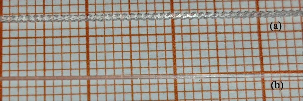
The heat loss from the crucible and the hot zone must be compensated during the growth process, which is the main reason of nonuniform of the diameter. So, fibers (diameter 400–1000 µm, length 500 mm) with good quality and regular shape were grown successfully in the following growth operations by more heat supplied, as shown in Fig. 2(b).
Three single-crystal fiber samples with length of 2 mmwere cut at different locations of 20, 90 and 150 mm away from the seed, respectively.
1.2 Numerical simulation
It is well known that fluid flow plays an important role in the processes of heat transport and mass transport in crystal growth from the melt. In order to determine the trajectory of a possible gas bubble located in the melt meniscus, the incompressible Navier–Stokes equations were considered:

1-Melt; 2-Crucible; 3-Die; 4-Meniscus; 5-Sapphire fiber; 6-Seed

Fig. 2 View of as-grown sapphire in which fibers with irregular shape (a) and regular shape (b)


The dimensionless governing equations with the mentioned boundary conditions (specified in the Fig. 3) have been solved using the CGSim software. The computations were made in the stationary cases: growing fiber with radius of 0.5 mm with pulling rate of 30 mm/h and meniscus height of 0.2 mm.
2 Results and discussions
2.1 Crystal growth and defects in crystals
The cross section of the fibers was roughly circular without noticeable faceting on the lateral surface of the fiber. The diameter variation was within 40 µm in the whole fiber. Facets appeared only on one side of the-plane. The facet probability of the sapphire fiber grown along the-axis was defined by anisotropy of the surface energy and melt temperature fluctuations. Temperature instability also could induce the non-uniform lateral or normal facet growth, which could lead to defects and surface roughness shown in Fig. 4 and Fig. 5.

Fig. 3 Schematic diagram of the boundary conditions used in the numerical simulation

Fig. 4 Growth stripes in the crystal structure caused by slight vibrations above the die, v=30 mm/h

Fig. 5 Cross section morphology and bubbles' distribution in the cross section of the sapphire fibers
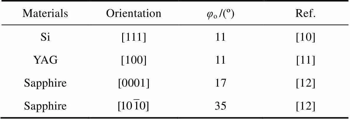
Fig. 6 shows the principles of the capillary shaping for EFG fiber growth method. It can be seen that stable shaped single crystals with constant diameter will be grown if the growth angle(the angle between the meniscus and the growth axis) is constant (o). As a material constant, the parameterowas determined by the thermodynamic equilibrium condition at the three-phase interface line, which does not depend on the growth parameters like pulling velocity, diameter and meniscus height. The parametersoof different crystals are given in Table 1.

Fig. 6 Principles of capillary shaping for EFG fiber growth method
m-Vertical curvature of the meniscus;d-Die radius;c-Radius of the crystal;m-Meniscus height

Table 1 Parameter φo for different crystals
Deviations of the actual growth anglefromoresult from perturbations of the meniscus height and radius, which lead to non-stationary variations of the fiber radii in agreement with:

The relationship between meniscus shape and crystal radius is given by the equation[12]:

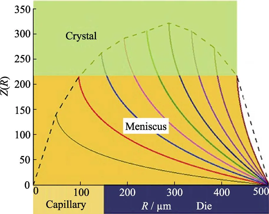
The relationship of theoretical meniscus shapes() and different fiber radiicis shown in Fig. 7. For the actual fiber geometry, meniscus shapes with different fiber radiicvalues were calculated. The dashed line shows the possible positions of the meniscus. There is a certain range of meniscus height for successful growth of crystals. The increase of height will induce the separation between the growing crystal and the meniscus. The decrease of height will cause the local interaction between the growing crystal and the die surface, which will reduce the crystal quality. The meniscus height depends on the material properties of the melt, pulling rate and ambient temperature distribution. The stable meniscus height and regular crystal shape can be achieved when temperature gradient at growth interface area was invariable. However, it is not easy to establish such conditions during the entire crystallization process. In order to maintain a stable meniscus height, we have to use an automated control system with computer-controlled feedback program that simultaneously monitored and controlled the fiber diameter and the die temperature. At the same time the pulling rate was invariable.

Fig. 7 Relationship between theoretical meniscus shapes Z(R) and different fiber radii R
The characteristic defects in sapphire crystal were the so-called voids or bubbles, which could reduce the optical and mechanical quality of crystals. In this work, sapphire fibers were studied with an optical microscope with 50× magnification. It was shown that there were bubbles running along the fibers. Fig. 8 shows a 50× micrograph of the EFG sapphire fiber.
The size of micro bubbles was about 5–10 µm. The most bubbles were spherical and exist on the periphery of the fiber. The distribution behavior of micro-bubbles was fairly related to growth rate and impurity effects (constitutional super cooling). Their occurrence has been demonstrated to be related to the stability of the solid liquid interface[13-14].
Another defect of the fiber was the Mo inclusions. As shown in Fig. 4, a small amount of Mo inclusions were observed, which are re-crystallized from solution in the sapphire. The Mo is generally oxidized by dissociation of the melt. The oxide dissolves in the melt, and is reduced to yield metallic molybdenum. This mechanism would seem to be confirmed by the appearance of the Mo in the inclusions. However, other aspects play a role on the generation of Mo inclusions. Notably, the new dies would produce more Mo inclusions at the first several runs as shown in Fig. 9(a).
In Fig. 9(a), the total content of Mo decreased with the frequency use of the crucible and die. It is concluded that new setups with the rougher machining surface, which leads to easier dissolution of Mo and increases the “output” of Mo into the melt. The high initial content of Mo inclusions can be seen when the crucible and die were first used. Another possibility is due to the poor vacuum of the equipment which results in more content of molybdenum oxide. Other experiments have sought to establish the “time relationship” of Mo in sapphire fibers. The Mo concentration in the samples measured by ICP analysis and the results were in Fig. 9(b).

Fig. 8 Bubbles’ distribution observed on the lateral periphery of the fiber

Fig. 9 Decrease in total Mo inclusion length with die life (a) and Mo concentration as a function of time from a sapphire melt (b)
Mo seems to be produced in substantial amounts early in the usage of the setup, and then diminishes after several runs. The die and its surroundings are likely the coldest part of the setup. It is apparent from examining used die that significant amounts of Mo are precipitated out on the outer surfaces.
2.2 Bubbles distribution and numerical simulation result of the fluid flow in the meniscus
The flow field in the meniscus (fiber radius 0.5 mm) and the corresponding bubbles in the crystals were shown in Fig. 10.

Fig. 10 Flow field in the meniscus (fiber radius 0.5 mm) and corresponding bubbles in the crystals
The available experimental data suggest that the micro- bubbles distribution depends on the fluid flow in the meniscus. The distribution of the bubbles in the periphery of the meniscus suggested that the vortex of the fluid flow drove the bubbles move to the atmosphere under the thermo-capillary convection. The positions of these regions depend on the geometry shape of the die[15].
2.3 Optical properties
The absorption spectrum of the EFG sapphire fiber was shown in Fig. 11. The measured attenuation coefficient of the EFG fiber with length of 76 cm was 9 dB/m at 633 nm. The crystal quality of grown crystals by EFG method was worse than the crystals grown by LHPG method[16]. Low propagation loss is necessary for optical applications of sapphire fibers. Two effects such as scattering and absorption induce the total loss. Absorption loss comes from the micro-bubbles defects and the impurities. In the grown sapphire fiber, the density of molybdenum ions will reach up to 5×10⁻⁶g/cm3due to the molybdenum crucible used in the growth process. The impurities in the melt were also the reason of extrinsic absorption. Inclusions, inhomogeneous, and surface irregularities increase the scattering losses. There is no any inhomogeneous defect observed under the optical microscopy, and no scattering centers under laser illumination. It is suggested that diameter variation should be the most important reason for the scattering loss. The variations in diameter could be induced by several following factors: heating power fluctuations in the molten zone and the mechanical perturbations. The latter could induce bending or twisting of fiber.
3 Conclusion
Single-crystal sapphire fibers (diameter (400–1000) µm, length 500 mm) were grown with the EFG method successfully. The cross section of theaxis fibers was roughly circular. The defects such as micro-bubbles, inclusions and growth stripes were observed and analyzed. The distribution of the micro-bubbles was studied with optical microscopy. The influence of the growth conditions on the size and distribution of micro-bubbles in sapphire fibers has been studied by experimental and numerical simulation of the fluid flow in the meniscus. The defect analysis and optical characterization exhibited the imperfect single crystalline structure of fibers.

Fig. 11 Absorption spectrum of the EFG sapphire fiber
[1] LABELLE JR H E. EFG, the invention and application to sapphire growth., 1980, 50(1): 8–17.
[2] WILSON B A, PETRIE C M, BLUE T E. High temperature effects on the light transmission through sapphire optical fiber., 2018, 101(8): 3452–3459.
[3] COULTER A H. Sapphire fibers for erbium: YAG continue to evolve., 1995, 13(3): 227–228.
[4] KURLOV V N, STRYUKOV D O, SHIKUNOVA I A. Growth of sapphire and oxide eutectic fibers by the EFG technique., 2016, 673(1): 012017.
[5] BERA S, NIE C D, SOSKIND M G,. Growth and lasing of single crystal YAG fibers with different Ho3+concentrations., 2018, 75: 44–48.
[6] LEBBOU K. Single crystals fiber technology design., 2017, 63: 13–18.
[7] KURLOV V N, MILEIKO S T, KOLCHIN A A,. Growth of oxide fibers by the internal crystallization method., 2002, 47(1): S53–S62.
[8] KURLOV V N, KIIKO V M, KOLCHIN A A,. Sapphire fibres grown by a modified internal crystallisation method., 1999, 204(4): 499–504.
[9] FITZGIBBON J J, COLLINS J M. High-volume production of low-loss sapphire optical fibers by Saphikon EFG (edge-defined, film-fed growth) method., 1998, 3262: 135–141.
[10] SUREK T. Theory of shape stability in crystal growth from the melt., 1976, 47(10): 4384–4393.
[11] RUDOLPH P, FUKUDA T. Fiber crystal growth from the melt. crystal research and technology., 1999, 34(1): 3–40.
[12] KAMADA K, MURAKAMI R, KOCHURIKHIN V V,. Single crystal growth of submillimeter diameter sapphire tube by the micro- pulling down method., 2018, 492: 45–49.
[13] ZHDANOV A V, SATUNKIN G A, TATARCHENKO V A,. Cylindrical pores in a growing crystal., 1980, 49(4): 659–664.
[14] TATARCHENKO V A, YALOVETS T N, SATUNKIN G A,. Defects in shaped sapphire crystals., 1980, 50(1): 335–340.
[15] BUNOIU O, NICOARA I, SANTAILLER J L,. Fluid flow and solute segregation in EFG crystal growth process., 2005, 275(1/2): e799–e805.
[16] NUBLING R K, HARRINGTON J A. Optical properties of single- crystal sapphire fibers., 1997, 36(24): 5934–5940.
导模法生长蓝宝石单晶光纤的缺陷和光学特性研究
王东海1, 侯文涛1, 李纳1, 李东振2, 徐晓东2, 徐军1, 王庆国1, 唐慧丽1
(1. 同济大学 物理科学与工程学院, 上海 200092; 2. 江苏师范大学 物理与电子工程学院, 徐州 221116)
通过导模法(EFG)成功生长了蓝宝石单晶光纤(直径400~1000 µm, 长度500 mm)。光纤的横截面大致为圆形, 侧面无明显的小面, 直径变化小于40 µm。本研究对晶体缺陷, 例如微气泡, 包裹物和生长条纹等进行观察与分析, 得出: 大多数微气泡是球状的, 且存在于光纤的外侧缘; 在蓝宝石光纤外侧面也观察到少量的钼包裹物元素; 新模具在前几次使用中往往会产生更多的钼夹杂物, 在多次使用后降低。通过对熔体膜流体流动的实验和数值模拟, 研究蓝宝石光纤中微气泡尺寸和分布, 实验和数值模拟的结果显示出良好的一致性。微气泡的分布取决于熔体膜处的流体流动模式, 流体流动的涡流使微气泡在热毛细对流作用下移动到蓝宝石光纤外侧缘。633 nm处的吸收损耗为9 dB/m, 包裹物和表面不规则性会增加散射损耗。
蓝宝石光纤; 导模法(EFG); 微气泡; 钼包裹物
TQ174
A
date:2019-11-11;
date: 2019-12-25
WANG Donghai(1982–), male, PhD candidate. E-mail: yingxiong3258@sina.com
王东海(1982–), 男, 博士研究生. E-mail: yingxiong3258@sina.com
Corresponding author:XU Jun, professor. E-mail: xujun@mail.shcnc.ac.cn; WANG Qingguo, PhD. E-mail:wqingguo2013@163.com
徐军, 教授. E-mail: xujun@mail.shcnc.ac.cn; 王庆国, 博士. E-mail:wqingguo2013@163.com
1000-324X(2020)09-1053-06
10.15541/jim20190573

