Experimental investigation on the evolution of plasma properties in the discharge channel of a pulsed plasma thruster
Yang ZHOU (周阳), Ningfei WANG (王宁飞), Xiangyang LIU (刘向阳),William Yeong Liang LING (林永樑), Kan XIE (谢侃) and Zhiwen WU (武志文)
School of Aerospace Engineering, Beijing Institute of Technology, Beijing 100081, People’s Republic of China
Abstract Pulsed plasma thrusters (PPTs)are an attractive form of micro-thrusters due to advantages such as their compactness and lightweight design compared to other electric propulsion systems.Experimental investigations on their plasma properties are beneficial in clarifying the complex process of plasma evolution during the micro-second pulse discharge of a PPT.In this work,the multi-dimensional evolutions of the light intensity of the PPT plasma with wavelength,time,and position were identified. The plasma pressure was obtained using an iterative process with composition calculations. The results show that significant ion recombination occurred in the discharge channel since the line intensities of CII,CIII,CIV,and FII decreased and those of CI and FI increased as the plasma moved downstream. At the center of the discharge channel, the electron temperature and electron density were in the order of 10 000 K and 1017 cm-3,respectively. These had maximum values of 13 750 K and 2.3×1017 cm-3 and the maximum temperature occurred during the first half-cycle while the maximum number density was measured during the second half-cycle.The estimated plasma pressure was in the order of 105 Pa and exhibited a maximum value of 2.69×10⁵ Pa.
Keywords: pulsed plasma thruster, plasma properties, emission spectra, electric propulsion
1. Introduction
The recent increasing growth in the number of satellites and space applications has resulted in a demand for reliable and versatile space propulsion systems. There is an increasing number of satellites equipped with electric propulsion in recent years instead of the well-established chemical propulsion[1].This is due to their significant advantage of a higher propellant efficiency [2].Among electric propulsion systems,pulsed plasma thrusters (PPTs), which have attracted much attention so far [3–5], can offer a wide range of performance depending on their design and energy input. Therefore, they may be suitable for various applications, especially for small satellites.
In a solid-ablative PPT, the energy stored in a capacitor or a capacitor bank is discharged across the surface of a solid propellant, and then a part of the propellant is decomposed into plasma. After that, the charged particles are accelerated by the self-induced magnetic field [6].
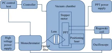
Figure 1.Structural diagram of the experimental system.
It is to be expected that discharge characteristics such as plasma acceleration[7]and the efficiency of the thruster[8]will show a strong dependence on the properties of the plasma.The plasma accelerated by the electromagnetic force in the discharge channel is the main source of thrust, and so its acceleration is influenced by the plasma properties. An improvement in performance is often reflected by an improvement in the efficiency and could be achieved through optimizing areas such as the propellant, electrode structure, and external electric circuit. The study of the plasma properties can provide new directions towards new solutions. Information regarding the plasma components can guide the selection of dopants for the propellant[9].An understanding of the plasma distribution can help in the optimization of the electrode structure [10]. Finally, an investigation into the evolutionary processes of the plasma properties can help us to optimize the parameters of the external circuit.
The plasma is divided into the part in the discharge channel and the part outside the discharge channel. Since the plasma acceleration process is mainly completed in the discharge channel,the plasma in the channel can directly reflect the performance of the PPT. Typically, the part outside the channel is referred to as the plume and is often investigated in studying the effect of plume contamination on satellites since it provides little contribution to the thrust. As a result,experimental investigations on the plasma properties in the discharge channel are beneficial in clarifying the complex processes of plasma evolution during the short micro-second pulse discharge of PPT.
Research has been done to investigate the plasma properties in PPTs. In 1998, Burton et al investigated the performance of a PPT and found that the ions, constituting 10%of the mass,carry nearly 50%of the kinetic energy and about 25% of the impulse bit [11]. In 2007, Hiroyuki et al investigated the plasma acceleration processes and obtained spectral data from only two wavelengths, albeit with a high temporal resolution. He found that high density, ablated neutral gas stays near the propellant surface, and only a fraction of the neutrals is converted into plasma and electromagnetically accelerated,leaving the residual neutrals behind
[12]. In 2013, Schönherr et al investigated the plasma properties with variations in time and space[13],but the variation in the plasma properties recorded with a 2 MSa s-1sampling rate was not fast enough to record a continuous variation in the short microsecond time scale of the pulsed plasma. In 2016, Zhang et al conducted similar spectral diagnostics and found that there is a big difference in the proportion of plasma components between different discharge stages[14].In 2019,Min Gyoung Cho developed a numerical model employing the ablation rate and ionization of Teflon to analyze PPT performance. The ionization tendency of the sublimed propellant was found to vary with the position and time between two electrodes. Also, it was confirmed that the ionization of Teflon particles affected the plasma resistance value and the discharge current.
As mentioned above, the short pulse discharge of a PPT results in variations in the plasma properties with time and space. Research on various aspects of the plasma characteristics through experiments, usually emission spectroscopy[15, 16], and simulations, can give us a relatively good understanding of the performance of PPT. However, there is still a lack of comprehensive understanding and mastery of plasma behavior during the micro second level discharge of PPT in terms of time and space because it requires sufficient resolution in both time and wavelength,which was lacking in previous studies. In addition, the results obtained by some simulation also lack the support of relative experimental results.
In this research, emissive spectroscopic experimental investigations of the plasma evolution were conducted with higher temporal and wavelength resolution of the plasma spectra,which supplied abundant information that will help in clarifying the complex underlying plasma generation and evolutionary processes. The experimental setup is introduced in section 2.Some important issues regarding data processing,especially for the plasma pressure and plasma evolution process, are discussed in section 3. Plasma evolution characteristics such as the electron temperature and electron density in the discharge process are further analyzed in section 4. The conclusions are given in section 5.
2. Experimental setup
2.1. Setup of the test facility
A structural diagram of the experimental system is shown in figure 1. It is mainly comprised of a PPT prototype, a PPT power supply, a vacuum chamber, a Rogowski coil, an oscilloscope, and an optical emissive spectroscope (OES).
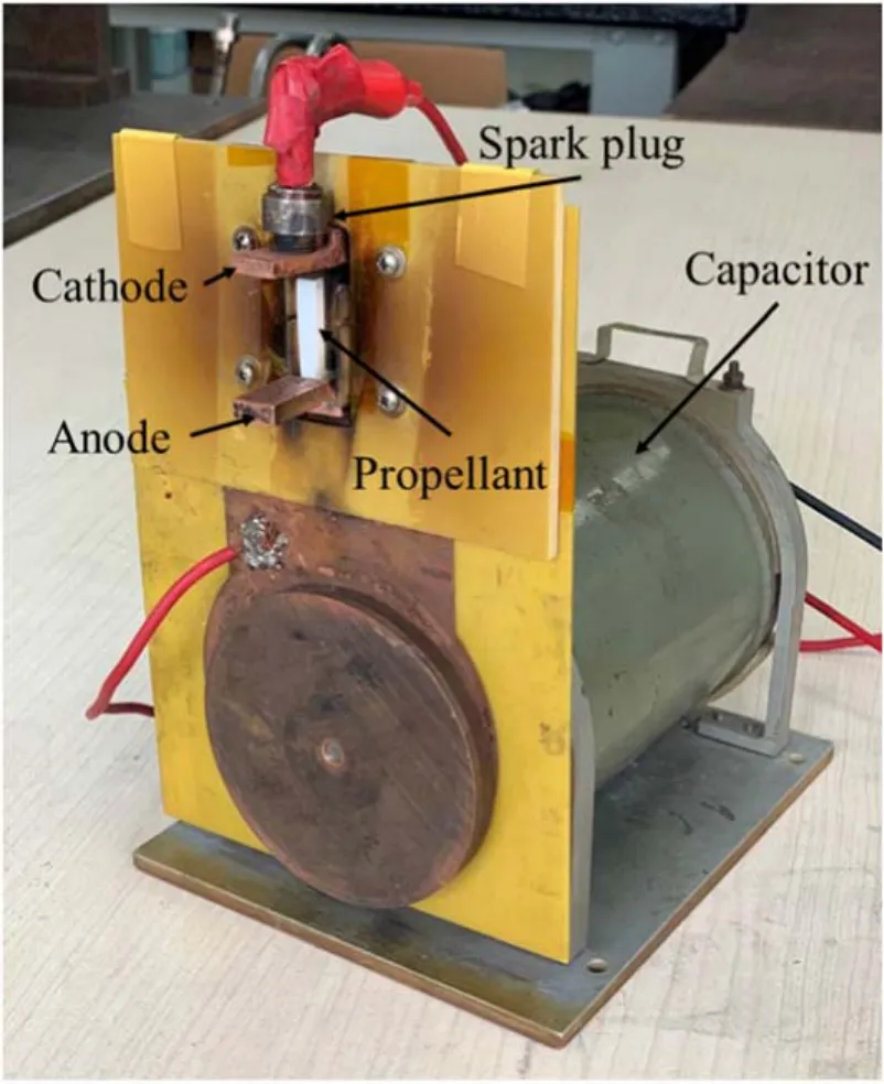
Figure 2. The PPT used in this study.

Table 1. Parameters of the PPT.
For the experiment in this study, a breech-fed PPT was used and is shown in figure 2. The PPT consists of a propellant bar, usually polytetrafluoroethylene (PTFE aka.Teflon), two rectangular electrodes, a spark plug, and a capacitor. When the PPT operates, the spark plug provides a small amount of initial plasma, triggering the main electrical discharge from the capacitor across the exposed surface of the propellant. This then causes ablation and ionization of the propellant and part of the propellant becomes plasma. After that, the plasma is accelerated mainly by the electromagnetic force and ejects along the discharge channel. The parameters of the thruster are shown in table 1.
The PPT power supply has two functions: charging the capacitor and controlling the ignition. It is capable of single pulse ignition or ignition at a specific frequency.
The vacuum chamber is used to simulate the space environment in which a PPT typically operates. Its diameter and length are 1.8 m and 3 m, respectively. The vacuum pressure was maintained at approximately 5×10⁻³Pa during the experiments. The discharge current was measured using a Rogowski coil, and was recorded using a digital oscilloscope with a data sampling rate of 100 MSa s-1.
2.2. Description of OES setup
The OES setup includes a monochromator with its power supply, two lenses, a stepper motor, a PC control host, and a controller. A 7ISW30 tri-grating monochrometer supplied by Sofn Instruments Co. Ltd was adopted to select the indicated wavelength. It has a wavelength-selection precision of 0.0023 nm and a gramming precision of 1200, 600, and 300 g mm-1for peak wavelengths of 300,750,and 1250 nm,respectively. Collimating lenses were used for focusing in order to let enough light enter the light path in the limited spatial scale.The stepper-motor drives the platform where the PPT is set up to obtain the indicated position.The wavelength selection and the motor adjustment are achieved with the help of software on the PC control host and the controller.
In order to identify the position of the PPT,a positioning laser is used to simulate the light the PPT emits in the atmosphere where PPT does not function.The initial position was set as the surface of the propellant and identified by finetuning the stepper motor. Different spatial positions could be obtained by further adjusting the stepper motor.
The wavelength of the OES was calibrated using a mercury lamp. The light intensity was calibrated with an Ocean Optics HL-2000-CAL calibration source,which has a spectral range of 300–1050 nm with a power of 1–90 μW cm-2nm-1.
The process of the spectroscopic experiment was as follows. Before the experiments, the initial position was identified with the help of a positioning laser. The vacuum chamber was then closed and pumped to the defined pressure.A wavelength of interest was set in advance of the PPT shot.The PPT was then ignited and the current and light intensity at that wavelength were collected. Another wavelength was chosen for the next PPT shot. When the spectra of all indicated wavelengths were obtained, the PPT was moved to another position to repeat the data collection process.
Some special techniques were used to ensure the resolution of the time and wavelength. The high temporal resolution requirement was realized with the use of a digital oscilloscope. A high wavelength resolution was achieved using a monochromator. The discharge current was collected as a time reference at the same time to align the spectral data from different shots.
All the selected wavelengths have been shown in previous research to have high relative intensities [6]. A specific wavelength with strong light intensity was chosen as the representative of each component. The plasma components identified in the experiments were CI (711.853 nm), CII (392.069 nm),CIII (465.22 nm), CIV (581.4 nm), FI (703.952 nm), and FII(384.91 nm).Wavelengths of 392.069 nm,426.726 nm,and 657.77 nm corresponding to CII emission were chosen to calculate the electron temperature. Five wavelengths near 658 nm were chosen to calculate the electron density.
The spectra at three positions along the centerline of the discharge channel were measured.They were 1,7,and 14 mm from the propellant surface in the direction of the plasma exhaust and represented plasma conditions such as the plasma pressure at the start,middle,and end of the discharge channel.
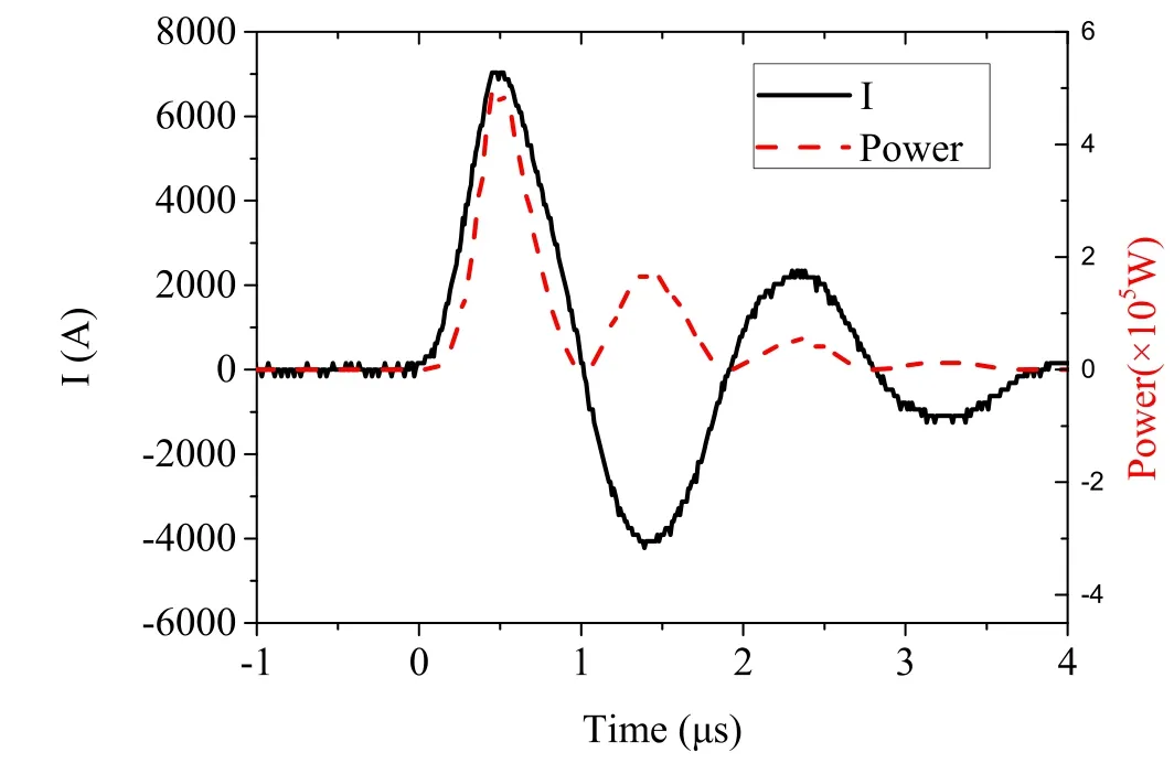
Figure 3. Discharge current and instantaneous power.
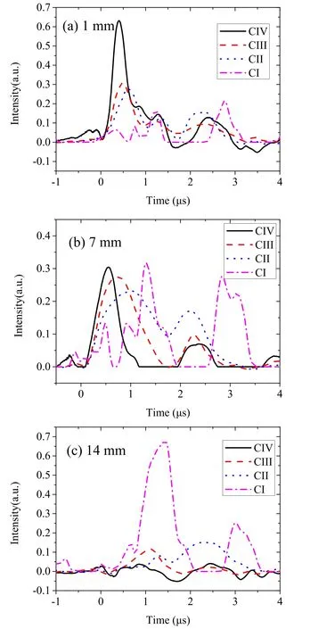
Figure 4.Change in emission from carbon components along the centerline of the discharge channel.
3. Results and discussion
3.1. Variation in spectral measurement results with time
Examples of the discharge current waveforms and instantaneous power of the PPT in these experiments are shown in figure 3. This will be beneficial in analyzing the energy transitions in the PPT. There are a large number of ablation products in the first half cycle with a 1 μs duration, which is also the main period of the thrust produced by the plasma.After that, ablation still continues, but the ablation products are ionized less because of its lower energy level.
The spectroscopic signals from some points along the centerline of the discharge channel were measured. Figures 4 and 5 show the evolution of carbon and fluorine particles with different valences at three different positions during the discharge.It is apparent that these four types of particles peak at almost the same time near the propellant surface(figure 4(a)).However, the peak times of the four particles are different at the center of the discharge channel (figure 4(b)), and CIV appears first, followed by CIII, CII, and CI. This out-of-sync phenomenon is due to the difference in particle speed. The high-valence ion moves faster than the low-valence ion.
Considering the three positions in figure 4, it can be found that CIV produced near the propellant surface is more apparent than the others,but the difference in the center of the discharge channel is not so evident. At the exit of the discharge channel, CIV and CIII almost disappeared while the others still exist. This shows that the closer we are to the propellant surface, the more likely that the high-order ionization will occur. Related phenomena can also be seen in figure 5.
The emission spectra show multi-peak curves. However,the number of peaks changes from 3 at the 1 and 7 mm positions to 2 at the 14 mm position near the exit of the discharge channel. For the position near the propellant surface, the peak times of the spectrum are comparable with the three peaks of the instantaneous power.The fourth peak of the instantaneous power is too small to cause an obvious change in the spectrum. The variation in the number of peaks indicates that the separate plasma bulks from different half-cycle discharges fuse as they move downstream.
The variations in the first peak at different positions for each component are compared in figure 6. The three points in each line represent the peak value at the three different positions.To simplify the elemental analysis, FI and FII were selected as representatives.The peak value of FII became smaller while that of FI became larger during downstream propagation. This indicates that the recombination of FII with free electrons occurs to produce FI.A similar phenomenon could also be observed for C ions. It can be concluded that significant ion recombination takes place inside the discharge channel.
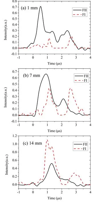
Figure 5. Change in emission from fluorine components along the centerline of the discharge channel.
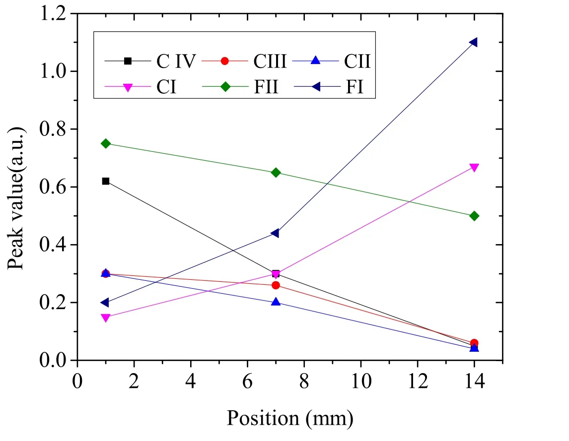
Figure 6.Peak spectral values of plasma components.
The occurrence of ion recombination is also partly supported by previous research.Schönherr et al observed that the spectral line intensity of CII, CIII, and FII showed a decreasing trend as the plasma moved downstream in the discharge channel of the ADD SIMP-LEX PPT, but the line intensity of CI and FI was not measured [13]. Koizumi et al observed the emission spectra from ions at 22 and 42 mm downstream from the PTFE propellant surface for a PPT with a 25 mm electrode length [12]. For almost all the emission spectra from ions and neutral particles, the signals at the position farther away from the propellant surface were much smaller than those nearer to the propellant surface.
The phenomenon where less ions exists at the 7 mm and 14 mm positions indicates that the second half of the discharge channel provides little contribution to the dynamic performance. It suggests that we may be able to improve the PPT by redesigning the second half of the electrodes or optimizing the propellant to resist ion recombination.
3.2. Variation in plasma properties with time
The calculation of the electron temperature is based on the local thermal equilibrium assumption(LTE).The distribution of atoms and ions at different energy levels can be determined using the Boltzmann law [17] and the electron temperature can be derived from the slope of the Boltzmann plot.
The electron density is obtained by Stark broadening,which is a commonly used method for calculating the electron density of plasma using spectral emission measurements[18].The total spectral line broadening profile of PPT plasma,which can be obtained through the experimental results, is a combination of Stark, Doppler and instrumental broadening[18]. Doppler broadening was assumed to be negligible [19].Instrument broadening was determined using a He–Ne laser with a wavelength of 632.8 nm (0.001 92 nm Lorentzian FWHM). To separate the instrument broadening from the total broadening profile, a deconvolution method was used.Based on the assumption that Stark broadening must be less than total broadening, the Stark broadening value was set in the range of the total broadening with a step of 0.002 nm.When the Stark broadening value was set,a new spectral line profile could be theoretically obtained and compared with the experimental results. The real Stark broadening was determined if the two line profiles agreed best.
The above conclusion of the peak time was not reached in previous research due to limitations in the spectrometer systems. Schönherr et al recorded the variation in plasma properties with a 2 MSa s-1sampling rate[13].The variation trend was not clear because the sampling rate was not fast enough to show the continuous variation.For this work with a 100 MSa s-1sampling rate,the entire evolutionary process is obtained more accurately and the continuous trend is clear.Furthermore,the establishment of a time reference provides a way to make comparisons between the plasma properties and the discharge waveforms.

Figure 7.Variation in plasma properties with time.
The variation in the plasma properties with time at the center of the discharge channel over a complete discharge is shown in figure 7.
In figure 7, the electron temperature is in the order of 10 000 K and the electron density is in the order of 1017cm-3.There appears two peaks in the electron density within the duration of one half-cycle (~1 μs). This is likely to be due to separation of the plasma components based on mass(as opposed to charge).Components with a greater mass will have a slightly lower velocity, and vice versa, with the plasma components from one half-cycle separating as they travel downstream. The results from this work are shown along with results from previous research in table 2. However, it must be noted that there are differences between the thrusters and operating conditions.
It is also worth mentioning that the peak values of the electron temperature and the electron density occur at different times. The peak value of the electron temperature was 13 750 K at 0.5 μs while the peak value of the electron density was 2.3×10¹⁷m-3at approximately 1.4 μs. It can be seen from figures 3 and 7 that the peak of the electron temperature appears with the first maximum of the current while the peak of the electron density occurs during the second half-cycle of the discharge current.
The phenomenon can be explained due to the velocity difference between ions with different ionization levels. The plasma temperature peak is caused by high-valence CIV and CIII ions.From figure 4(b),the intensity of CIV has a peak at 0.5 μs;the intensity of CIII is also relatively strong at this time.Since the higher-valence ions have a higher velocity,they will be the first to arrive at the measurement point(the center of the discharge channel).On the other hand,the plasma density peak is related to the CII ions. Out of all the components, the CII ions exhibit the highest density(see table 2),even though it has a lower intensity than CI in figure 4(b);the emission intensities of different ions are different.Since the CII ions have a lower velocity than CIV and CIII,the plasma density peak(which is associated with the lower valence CII ions) does not coincide with that of the plasma temperature (which is associated with the higher-valence ions).
3.3. Variation in plasma pressure with time
The plasma pressure was estimated in an iterative fashion because complete monovalent ionization was not assumed.The consistency between the calculated value and the experimental value of the electron number density was used to judge whether the pressure value was sufficiently precise.The theoretical model behind the component calculation
[20]is composed of the Saha equation,quasi-neutrality equation,particle conservation relation, and the law of partial pressure.For PTFE plasma, the Saha equation has the following expression:

The quasi-neutrality equation is

The particle conservation relation can be described as

According to the law of partial pressures, the plasma pressure can be defined as

where Pe,Pi,and Pnare the pressure components of electrons,ions,and neutral particles,respectively.Under the assumption of LTE, the expression for the pressure can be simplified to

where niand nnrefer to the densities of ions and neutral particles, respectively.
Let α be defined as

Then, the expression for the plasma pressure in equation (5) can be simplified as

where α is an unknown parameter that depends on niand nnfrom the calculation of the plasma components. Thus, aniterative process is necessary to estimate the plasma pressure if complete monovalent ionization is not assumed.

Table 2. Comparison of plasma properties.
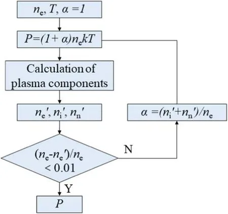
Figure 8. Estimation process for plasma pressure.
The estimation process is shown in figure 8. First, the initial value for the plasma pressure is estimated using the electron density value obtained from experiments. In this case, the initial value for the plasma pressure is estimated based on the assumption of monovalent complete ionization,i.e. α=1. Then, the plasma composition is calculated and
ne′, ni′, and nn′ are obtained. An iterative correction of the pressure estimation result is performed by comparing both the calculated and experimental results of the electron number density until the difference is sufficiently small. If ne′ is still not accurate enough, α will be adjusted using these three values.The iterative process continues until the estimated and experimental electron number density converges as shown in figure 8.At this point,a final value for the plasma pressure at a given time will be obtained.
The variation in the plasma pressure at the center of the discharge channel over a complete discharge is shown in figure 9. The pressure is in the order of 105Pa and has a variation trend similar to the electron number density. The peak pressure reached a value of 2.69×10⁵Pa.
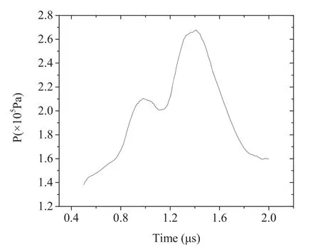
Figure 9. Variation in plasma pressure with time.
In this research, the plasma pressure in the discharge channel for a PPT has been estimated in detail using an iterative process. Scharlemann used a pressure probe to perform measurements on the plasma plume of a PPT [21]. He observed the dynamic process and the relative magnitude of the pressure.However,the absolute value of pressure was not obtained due to interference caused by the strong magnetic field in the discharge channel. Furthermore, the probe could not be used to measure the pressure due to the limitations of a contact structure. The magnitude of the pressure values here can be explained based on three points:the plasma ionization state, the operation state, and the measurement positions.Regarding the plasma ionization state, if the assumption of monovalent complete ionization is used, the estimated pressure will be in the order of 104Pa.The electron density values under such conditions do not match up with the experimental values. After the iterative process, we found that for the electron density values to match,the pressure has to be in the order of 105Pa, as shown in figure 9.
4. Conclusions
In this research,the plasma properties of a PPT were obtained with higher temporal and wavelength resolution, allowing us to evaluate the evolutionary process of plasma properties.The conclusions are as follows.
(1) Significant ion recombination occurs in the discharge channel. Ions of various valences are generated simultaneously near the propellant surface, but the density of high-valence ions decreases and that of low-valence ions increases as the plasma moves downstream.
(2) The electron temperature and electron density in the PPT were calculated to be in the order of 10 000 K and 1017cm-3, respectively.
(3) The maximum values of the electron temperature and the electron density at the center of discharge channel occurred during different periods of the discharge.
(4) The plasma pressure was estimated in detail and was found to be in the order of 105Pa.
Acknowledgments
This work was supported by National Natural Science Foundation of China (No. 51576018).
 Plasma Science and Technology2020年6期
- Plasma Science and Technology的其它文章
- Sensitivity of two drug-resistant bacteria to low-temperature air plasma in catheterassociated urinary tract infections under different environments
- First experimental results of intrinsic torque on EAST
- Gas pressure effect on plasma transport in a magnetic-filtered radio-frequency plasma source
- Design of a variable frequency comb reflectometer system for the ASDEX Upgrade tokamak
- Optimization of plasma-processed air (PPA)inactivation of Escherichia coli in button mushrooms for extending the shelf life by response surface methodology
- Reconstruction of hollow areas in density profiles from frequency swept reflectometry
