New turbulence modeling for air/water stratified flow
M.Ghafari , M.B.Ghofrani
Department of Energy Engineering, Sharif University of Technology, Azadi Ave., Tehran, Iran
Abstract
Keywords: Stratified flow; Turbulence model; Turbulence kinetic energy; Source function.
1.Introduction
Two-phase flow of gas and liquid as two fluids with major density difference is used in wide range of industrial appli- cations such as power plants and process systems.In each application, a special flow pattern would take place based on pipeline configuration and operation condition.For two-phase flow in a horizontal pipe, gas and liquid are separated by gravity effect known as stratified flow.At low relative veloc- ity, two fluids travel through the pipe with smooth interface in two separate layers.When the velocity of gas phase in- creases, a lift force due to pressure reduction in upper part reveals as destabilizing factor.This force would overcome the gravity in a certain relative velocity and lead to going up the interface.This condition is known as Kelvin-Helmholtz in- stability.Higher relative velocity increases the lift force and causes the waves at the interface to be picked up to form a frothy slug, known as slug flow pattern [8,30].
Stratified flow characteristics would affect the optimum performance (e.g., heat exchangers and oil industrial) or safety (e.g., pressurized thermal shock in pressurized water reactor) of an industrial system.In this region, phase change and high gradient of velocity cause some phenomena needing special treatment for simulation.Heat and mass transfer as two im- portant events at the interface depend on physical properties of phases and flow characteristics.Therefore, suitable model and simulation procedure should be employed at the interface to evaluate heat and mass transfer rate.Based on surface re- newal theory [14], heat and mass transfer at the interface of two-phase stratified flow are the function of surface renewal period which is related to characteristic velocity and length scale.Several models have been proposed for calculation of characteristic velocity and length scale based on turbulence characteristics at the interface [3,13,17,22].In addition to sur- face renewal theory, surface divergence model dealing with scalar exchange at the interface is based on correct calculation of velocity fluctuation components [2].So, turbulence simu- lation has a significant effect on heat and mass transfer rate at the interface of two phase stratified flow.

The velocity gradient intensifies turbulence kinetic energy when differential eddy viscosity models like k–εor k–ωmodel are used and some modifications should be considered in turbulence models at the interface [11,28].Implementation of turbulence damping function in turbulence eddy frequency transport equation is a solution for this problem.The damp- ing function at the interface decreases turbulence and dictates a new boundary condition similar to a solid boundary condi- tion [32].Although the new source function improves velocity profile of smooth stratified flow, but significant deviations re- veal when the vertical motion of the interface is considerable.Also, the turbulence kinetic energy would be underestimated by employment of damping function without the other modi- fication.The reduction of turbulence kinetic energy at the in- terface changes the value of heat and mass transfer coefficient and leads to underestimation of mass and energy transfer.
The final goal of this paper is to propose a new mod- ification in turbulence eddy viscosity k-ωmodel and, as a result, improvement of turbulence simulation at the interface.Section 2 of the present paper gives a review of conservation equations of mass, momentum and turbulence characteristics, and different model and improvement employed in literature.Section 3 illustrates the proposed modifications based on tur- bulence transport equation and in Section 4 the new approach is employed for smooth and wavy stratified flow of Fabre et al.[12]experiment and its effect on velocity and turbulence will be surveyed.
2.Two phase stratified modeling
2.1.Flow regime identification in horizontal pipeline
The identification of the flow regime in horizontal pipes plays an important role for simulation of these flows.Models for the transition from stratified flow to slug flow (or inter- mediate flow) are based on Kelvin-Helmholtz instability the- ory.According to this theory, small waves will grow when [21,25]:

In addition to this criteria, there are the other instabil- ity relations for stratified flow in literature considering more forces and phenomena at the interface.Thorpe [30]stud- ied dynamics aspect of instability in a rotated rectangular channel including two immiscible fluids experimentally and theoretically.Their results obtained the dynamics parameters such as critical wave-number and velocity disturbance and revealed the occurrence of Kelvin–Helmholtz and Tollmien–Schlichting instability.Lin and Hanratty [23]developed linear Kelvin–Helmholtz stability theory to predict the onset of slug flow for air–water flow.They considered the inertia of liq- uid phase and shear stress neglected in inviscid theory and showed ignorance of these effects is valid only for very large liquid viscosities.Brocchini and Peregrine [6]introduced L–q diagram for the interface shape identification based on mag- nitude of Froude number and Weber number for each point.They used turbulence kinetic energy and dissipation rate for calculation of turbulence length scale and velocity to predict the shape of the interface.
2.2.Conservation equations
Evaluation of interfacial flow characteristics in two-phase stratified flow needs non-resolved scales modeling.In this condition, utilization of statistic approaches, reflecting the in- fluence of these scales on averaged conservation equation, is the general solution in computational fluid dynamics.If ap- propriate models are employed, conservation equation of mass and momentum for gas and liquid would be effective to cap- ture these phenomena [5,11].The conservation equations of mass and momentum for isotherm condition are [18]:

In Eq.(2) ,Mireveals the effect of interphase momentum transfer including Drag, lift, added mass, turbulence disper- sion force and momentum associated to the interfacial trans- fer of mass.Calculation of this term is based on analytic and empirical correlation.In addition toMi, turbulence shear stress needs the other separate calculation procedure to reflect turbulence features of flow.Based on Boussinesq eddy vis- cosity assumption, turbulence shear stress can be related to the mean velocity gradients by the other transport equations of turbulence characteristics (for more information the reader is referred to Wilcox [32]).Therefore, solving of turbulence transport equations for gas and liquid phase is necessary to find turbulence shear stress.
Different approaches have been implemented for simula- tion of two-phase stratified based on conservation equations.Cerne et al.[7]coupled VOF (Volume of Fluid) and two fluid model for two phase stratified flow to utilize their advantages at the interface simultaneously.They proposed a special criterion for transition between two mentioned approach.Mouza et al.[26]employed CFX code for stratified flow with flat time-averaged interface shape and more attention to interfacial velocity and shear stress.Yao et al.[33]inves- tigated the turbulence production near the interface due to interfacial friction and showed that solid boundary condition is not valid at the interface, but their proposed model failed to predict turbulence characteristics for wavy flow.Bartosiewicz et al.[4]used the result of Thorpe’s experiment to survey the validity of two different multiphase flow approach.They consider Euler–Euler VOF in FLUENT and multi-field in NEPTUNE to simulate this experiment.Comparison with experimental result reveals the capability of VOF method in FLUENT and some distortions of multi-field method as a result of no assessment of different drag forces.But this validation of FLUENT and NEPTUNE accomplished for the fluids with no high density difference and would not grantee the maturity of them in gas–liquid stratify flow.Vallée et al.[31]investigated slug initiation of two different rectangular pipe and compared the experimental results with k–ωand SST turbulence model simulation.Terzuoli et al.[29]used Fluent, CFX and NEPTUNE for smooth air/water stratified flow and showed the effect of wall substitution at interface and 3D simulation advantage.Höhne and Lucas [15]developed Alge- braic Interfacial Area Density (AIAD) model.The rationale behind AIAD model is the selection of the drag coefficient based on local morphology detection.Coste and Laviéville [9]developed a model based on k–εturbulence model by fo- cusing on large interfaces.The result of this model predicted smooth flow characteristic and velocity profile of wavy flow, but an underestimation of turbulence kinetic energy revealed at interface.In addition to different procedures for solving conservation equation, turbulence overestimation due to high gradient of velocity at the interface needs special treatments for simulation of two-phase stratified flow.Employment of turbulence damping function at the interface is one of the conventional solution described in the next part.
2.3.Turbulence damping near free surface
The high gradient of velocity at gas/liquid interface is sim- ilar to flow condition near a wall.This condition dictates a specific behavior of turbulent characteristics not predicted in traditional two equations turbulence models.So, the other modification should be considered to bridge the gap.Liovic and Lakehal [24]employed large eddy simulation turbulence model at the interface of air jet injected into a water pool and demonstrated the effect of surface roughness on turbulence dissipation rate.Nourgaliev et al.[27]introduced sharp inter- face method based on level set method to capture sharp vari- ation of hydrodynamic characteristic by using a special func- tion at the interface.Ayati et al.[1]experimentally showed the effect of flow rate stratified flow of air and water on gen- eration of turbulence structure and dissipation of energy at the interface.Egorov et al.[11]proposed that a turbulence damping function is employed near the free surface of the stratified flow according to wall function of k–ωmodel [32].Wilcox [32]used Taylor approximation for fluctuation veloc- ity components as follows:

By using of mass conservation equation and velocity Tay- lor approximation, the fluctuation velocity components have the following behavior:

Substitution of velocity component in the definition of K andωobtains the variation of these variable near a wall as follows:

The same result can be obtained by consideration of stan- dard transport equations of k andωwhich is more favorable for interface gas/liquid interface.The standard transport equa- tions of k–ωmodel are [32]:

By consideration of velocity components near a solid boundary, these transport equations would be reduced in steady state condition and non-dimensional form as follow [19]:

Where

The singular solution of second transport equation satis- fying the flow condition at the solid boundary is similar to previous function ofω( Eq.(6) ).This value ofωis consid- ered as source term, known as turbulence damping function, for simulation of boundary condition at gas/liquid interface.Using this value forωimplies that the behavior of turbu- lence kinetic energy is according to Eq.(6) near the free surface.Therefore, the gradient of K would be zero at the interface.Höhne and Mehlhoop [16]used this damping func- tion in AIAD method for case 250 and case 400 of Fabre et al.[12]experiment.Although they improved the velocity profile of case 250, but deviations reveal in case 400 which the vertical motion of the free surface is considerable.The investigation of phenomena occurring in wavy stratified flow shows that the utilization of damping function is not suffi- cient.In addition to velocity, turbulence kinetic energy has a sharp variation near the free surface which is considered equal to zero near the wall.Obviously, the behavior of inter- face differs from solid boundary condition in some features affecting the flow characteristics and the other modification is needed for turbulence kinetic energy boundary condition illustrated in the next section.
3.New turbulence model near the free surface
3.1.Calculation of turbulence sources
Consideration of vertical component of velocity and nonzero boundary condition of turbulence kinetic energy and its gradient at the interface are two important factors neglected in previous turbulence model and this paper focused on a new model based on them.If turbulence eddy frequency of Wilcox [32]wall function is substituted into reduced transport equa- tion of turbulence kinetic energy ( Eq.(10) ), this equation can be solved as:

Where:

The powers of y+in k+equation is negative and positive.For solid boundary condition, it is assumed that the value of turbulence kinetic energy and its gradient is zero.So, the first term ofk+solution should be ignored and only positive power considered in calculation.If this boundary condition is applied for the interface of gas and liquid stratified flow, no source of k is needed near the free surface, whereas the in- vestigation of experimental results shows a sharp gradient of k occurring near the free surface.Therefore, the first term of Eq.(11) should be taken into account to reveal the high gra- dient of turbulence kinetic energy.On the other, the second term of Eq.(11) tends to zero when the distance of interface decreases.As the source function of turbulence kinetic energy will be implemented at the interface (where y+is small), it is possible to ignore this term in Eq.(11).By this assumption, one boundary condition is needed to specify the constant C1.There is no explicit boundary condition at the interface due to lack information of turbulence kinetic energy at the interface.So, the other type of boundary condition should be consid- ered based on flow behavior near the free surface.As the turbulence kinetic energy is a continues function in vertical direction, it is possible to assume that the value of turbulence kinetic energy (according to Eq.(11) ) approaches to value of turbulence kinetic energy far from the interface where no turbulence source function is implemented.As a result of this assumption, a certain distance from interface is considered for calculation of constant C1in Eq.(11).This distance should be far enough from the interface that interfacial effects could be ignored.The selection of this distance may have a major effect on the turbulence kinetic energy profile.So, a sensitiv- ity study is necessary to survey the impact of this boundary condition.For the first evaluation, the distance of y+= 400 is considered for this purpose leading to following equation for turbulence kinetic energy near the free surface:

As the velocity of gas phase increases, the new lift force leads to motion of free surface.So, the vertical component of velocity increases at the interface which do not reveals in a smooth flow.This phenomenon implies that transport term of k andωby convection in vertical direction increases near the interface and may affect the source function value of k andω.For investigation of vertical velocity effects, the vertical convection term of turbulence kinetic energy and eddy frequency are added to reduced transport equations ( Eqs.(9) and (10) ) as follows:

Unlike the previous reduced transport equation, no ana- lytical solution can be considered for Eqs.(13) and (14).In addition to this fact, the vertical component of velocity would be a function of y+at the interface and should be evaluated for solving these equations.As a result, only the numerical so- lution can be employed to find turbulence kinetic energy and eddy frequency function.Also vertical component of velocity is assumed to be independent on y+near the free surface.
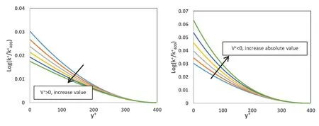
Fig.1.Turbulence kinetic energy profile near the free surface for positive and negative value of V +.
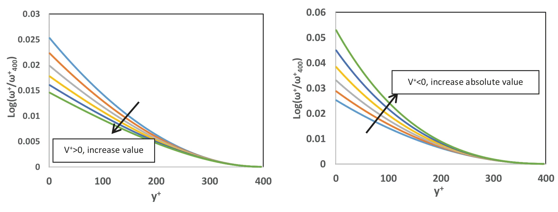
Fig.2.Turbulence eddy frequency profile near the free surface for positive and negative value of V +.
For numerical solution of Eqs.(13) and (14) with the as- sumptions illustrated in the previous paragraph, two different boundary conditions are needed for both differential equa- tions.The first type of boundary condition proposed in this section is similar to Eq.(11) and it is supposed that bothω+and k+are known far from the interface (y+= 400).The second boundary condition is defined due to reduction of tur- bulence source far from the interface.Actually, the source function of turbulence kinetic energy and eddy frequency will be employed near the free surface where the interfacial area density is large enough.In this region, the magnitude of both source should be very large and decreases when the y+in- creases.This behavior is similar to Eq.(12) without any con- sideration of vertical velocity.So, it is supposed that the vari- ation of turbulence sources far from the interface is equal to zero where those terms have no effect on transport equa- tions.By consideration of these boundary condition, numeri- cal method can be implemented for solving of Eqs.(13) and (14).Figs.1 and 2 depict the profile of turbulence kinetic energy and eddy frequency by implementation of proposed boundary condition and numerical solution for different value of V+.As shown in these figures, the convection term of both equations has significant effect of turbulence magnitude at the free surface.For high positive value of vertical veloc- ity, turbulence energy and dissipation rate decreases due to eddies transport out of interface while higher turbulence re- veals when the vertical velocity is negative.So, in addition to nonzero condition at the interface, vertical component of velocity and its direction should be considered at interface to employ for source function of turbulence.
For implementation of this new turbulence model, the nu- merical solution of two transport equations should be ac- complished for each point at the interface in all iteration leading to time-consuming calculation procedure.If Wilcox [32]proposed value of turbulence eddy frequency ( Eq.(6) ) is substituted in turbulence kinetic energy equation ( Eq.(14) ), the analytical solution of this equation is:

Where the constants c3and c4are two constants obtained from boundary conditions and the order of modified Bessel function, in Eq.(15) is:

By consideration of Wilcox [32]approximation for eddy frequency, the new function of turbulence based on modified Bessel functions will be implemented at the interface without any numerical calculation for source functions.As a result of the Wilcox [32]approximation for eddy frequency, the effect of vertical velocity on turbulence eddy frequency is ignored and turbulence kinetic energy will be calculated as a function of y+and v+analytical.The value of turbulence kinetic en- ergy and eddy frequency are added to transport equations as two source terms:

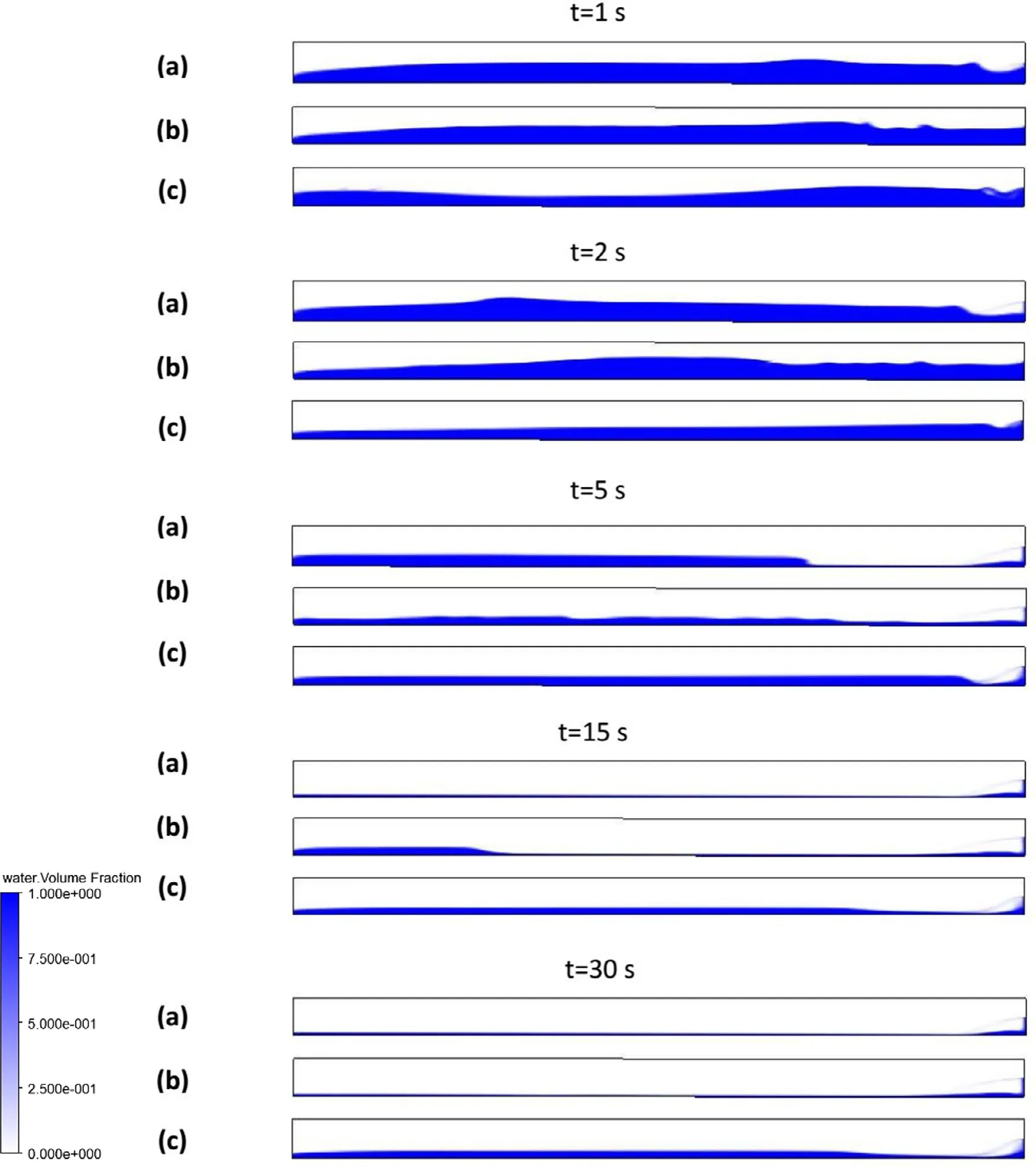
Fig.3.Illustration of water volume fraction for: (a) standard k–ω, (b) k–ω with damping function, (c) k–ω with source k and ω.

Where | ∇αi| is the value of interfacial area density and guar- antees the application of the source functions near the free surface and the value of k andωin Eq.(17) will be calcu- lated according to Eqs.(15) and (6).
3.2.Check of importance
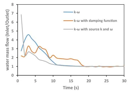
Fig.4.Water mass flow ratio at inlet to outlet during the simulation time.

Table 1 Pressure drop and mean water depth of rotated channel.
In the previous part of this section, a new turbulence source function was proposed to improve the turbulence prediction at the interface.Although the calculation of heat and mass transfer coefficient strongly depends on turbulence, but the change of turbulence equations at the interface may induce different hydrodynamic behavior for a system such as pres- sure drop and mass flow.In addition to this point, horizontal configuration of industrial pipelines may be distorted due to thermal expansion and sharp change of flow rate.In this sit- uation, a small inclination (e.g., 1 ° or 2 °) leads to different pressure drop and backflow which are very important for ther- mal system, especially in abnormal condition.To check the effect of turbulence model at the interface, a 2D rectangu- lar channel (0.2 m height and 5 m long) is considered that, att= 0 s, air and water flow with 5.5 m/s and 0.1 m/s velocity re- spectively and 0.1 m for the depth of water.Then, the channel is rotated 2 ° clockwise.Three different transient simulations (total time, 30 s) with different turbulence treatment are per- formed including standard k–ω, k–ωwith damping function and k–ωwith sources of Eq.(17).Fig.3 depicts water volume fraction contours with different turbulence models during the time.Before steady state condition, the shape of interface is different and the depth of water layer is not same along the channel.This condition causes different mass flow balance for every model.Fig.4 shows the ratio of mass flow at the inlet to mass flow at the outlet during the time.After the steady state, this ratio tends to 1 for conservation of mass but, after the rotation of channel, a significant differences reveals due to implementation of turbulent models.This disagreement be- tween the results of outlet mass flow shows the importance of turbulence model at the interface during transient condition.if, for example, a heat exchanger is installed at the outlet of the rotated channel, the major flow difference of water causes an incorrect assessment of heat removal at secondary side.In addition to transient part, the mean depth of water layer and pressure drop along the channel after steady state condition are different ( Table 1 ).The pressure drop and water depth of k–ωwith implementation of source k andωis almost two times larger than k–ωwith damping function which are two important parameter of thermal–hydraulic systems.So, in ad- dition to turbulence characteristics, the selection of the best turbulence model at the interface would change the other pa- rameters of a stratified flow.In this section, only the effect of domain rotation was investigated as one of the commoncondition in industrial processes.Flow rate, air humidity, mass transfer and shape of the channel are the other parameters that would exhibit the difference of turbulence models.This sec- tion is only the primary demonstration of these facts should be indicated in future numerically and experimentally researches.

Table 2 Inlet boundary condition for different scenario of Fabre et al.[12]experiment.
4.Validation of new turbulence function
The Fabre et al.[12]experiment of air and water strat- ified flow is selected to investigate turbulence characteristic near the free surface.In the test section of this experiment, an adiabatic co-current air and water flow passes through a 12 m long, 20 cm wide and 10 cm high rectangular channel.Air and water are separated at the channel inlet by a Plexiglas sheet that can be changed in different condition.To investigate different flow pattern of stratified flow, three different exper- iments are performed namely case 250, case 400, case 600.The flow characteristics of each case are listed in Table 2.The inlet gas superficial velocity of case 250 is weak enough for waves to be negligible and the velocity of case 400 and 600 is high enough for waves circulation [10].The measure- ment of velocity and turbulence characteristic is performed at vertical line at a distance of 9.1 m from inlet.
CFX Command Language (CCL) of ANSYS package was employed to simulation of Fabre et al.[12]experiment.Air and water were considered as two different isotherm continues fluid.Constant velocity inlet boundary condition according to superficial velocity of each phases was defined for air and water separately and constant pressure value is considered at the whole outlet.surface turbulence model was implemented for both phase with source function of k andωnear the free surface by calculation of interfacial area density value.All simulations were performed in transient scheme with time step of 0.001 s.
For selection of favorable grid size for this channel, it is needed to survey the effect of each nodalization on results.Höhne and Mehlhoop [16]investigated three nodalization and showed the convergence of grid study for (3.03 mm, 2.94 mm, 5.00 mm) mesh size.Also Coste and Laviéville [9]showed the convergence for (5 mm, 2.5 mm, 26 mm) mesh size.So, the first mesh size is selected with one modification at the interface.As turbulence modeling requires fine grid resolution in viscos sublayer, the vertical size of grids at this region is considered 1 mm [11].Also, the interfacial friction empirical correlation of stratified flow proposed by Kim et al.[20]is used for drag coefficient at the interface.
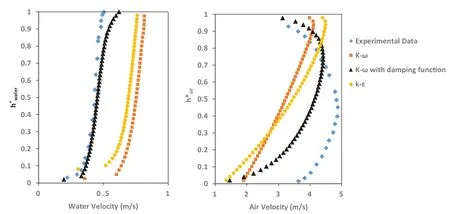
Fig.5.Velocity profile of water (left) and air (right) of Case 250 with different turbulence model.
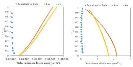
Fig.6.Turbulence kinetic energy profile of water (left) and air (right) of Case 250 with k–Ԑ and k–ω model.

Table 3 Pressure drop prediction for different model of Case 250.
4.1.Smooth stratified flow (case 250)
In this case the velocity of air and water lead to smooth surface and vertical velocity magnitude of air and water is very small.In this condition, the assumption of solid bound- ary condition at interface would be valid.So, only the source ofωis added to turbulence transport equation.A mean depth of water was computed for every simulation, ¯h, and normal- ized height for air and water were defines as the follows:

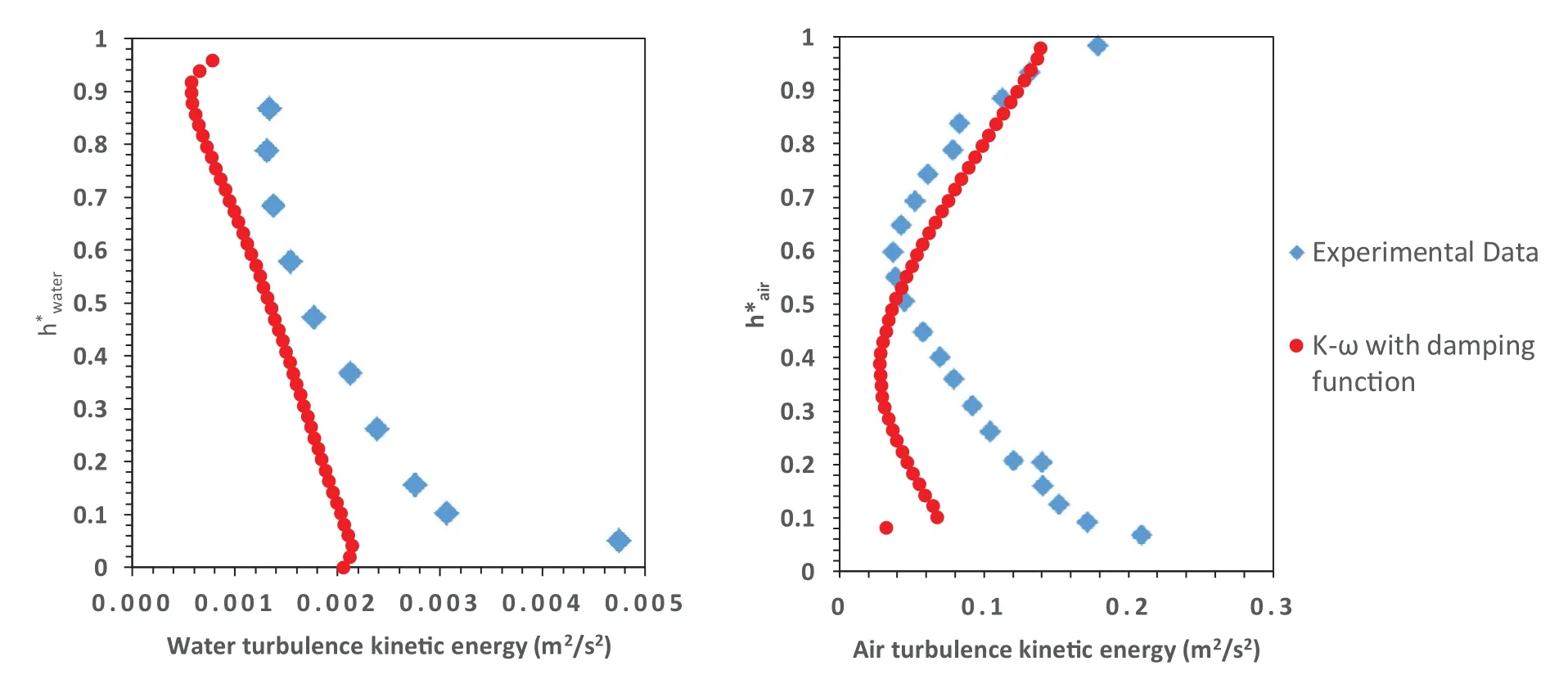
Fig.7.Turbulence kinetic energy profile of water (left) and air (right) of Case 250 with turbulence damping function.
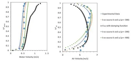
Fig.8.Velocity profile of water (left) and air (right) of Case 400 with employment of different source function.
Fig.5 shows the velocity profile for water and air versus normalized height.Experimental results for air and water re- veals same variation of velocity near the channel wall.But k–ωand k–Ԑ model without any modification fail to pre- dict this similarity.On the other, consideration of turbulence damping function at the interface improves the results for air and water.The maximum velocity of air approaches the center line of channel which is similar to velocity profile in simple channel.In addition to different profile shape of k–ωand k–Ԑ model, the average water velocity of both model is more that inlet boundary condition.As the mass flow rate is constant, this different implies deviation of water depth prediction af- ter reaching steady state condition.This overestimation has a significant effect on pressure drop which is an important parameter for thermal-hydraulic system design.Table 3 sum- marizes the magnitude of pressure drop and average pressure gradient.For Fabre et al.[12]experiment only the average pressure gradient was reported for every case.According to Table 3 pressure difference predicted by k–ωand k–Ԑ models is larger than experimental data as a result of reduction of water depth.On the other hand, consideration of turbulence damping function improves pressure drop estimation.
Fig.6 depicts Turbulence kinetic energy profile predicted by traditional eddy viscosity turbulence method.The over- estimation of turbulence near the free surface is very clear in this figure as main shortcoming of these model at two- phase stratified flow.If only turbulence damping function is added to transport equation, the sharp increase of turbu- lence kinetic energy will be captured as shown in Fig.7.Although this approach delivers good results for turbulence kinetic energy, but the underestimation of turbulence near the free surface is noticeable and can be intensified in the other condition.
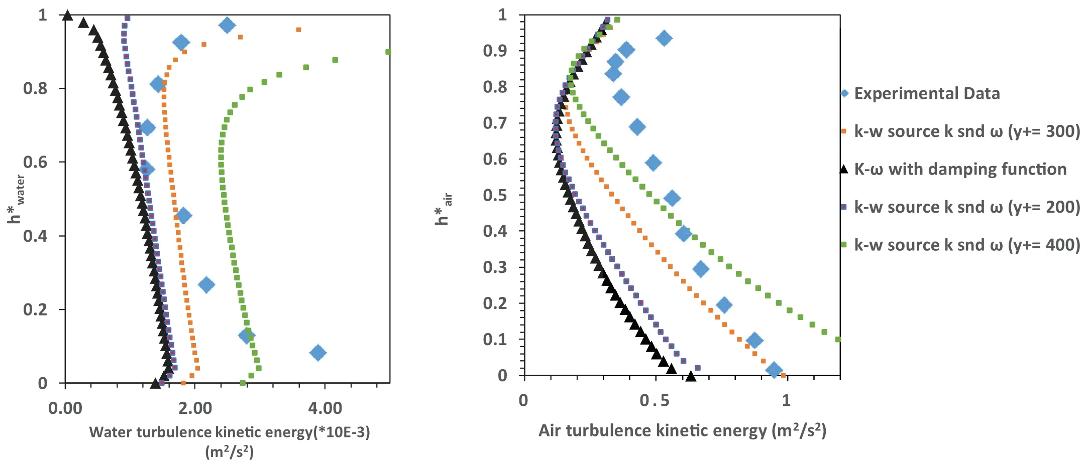
Fig.9.Turbulence kinetic energy profile of water (left) and air (right) of Case 400 with employment of different source function.
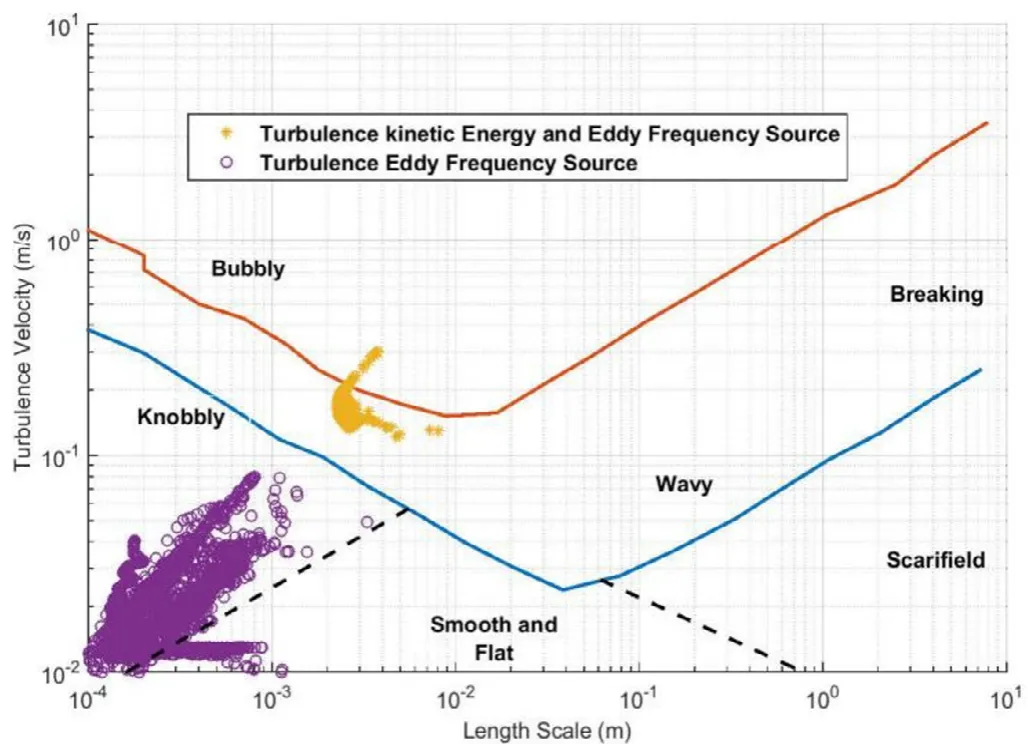
Fig.10.Comparison between flow pattern prediction base on turbulence length scale and velocity (based on Brocchini and Peregrine [6]).
4.2.Wavy stratified flow (case 400)
The next two-phase scenario of Fabre et al.[12]experi- ment is based on increasing of air velocity to propagate fluc- tuation at the interface.In case 400, the flow rate of gas increases with no change of water flow rate.As a result, the depth of water film in channel reduces to 3.15 cm and minor change in water velocity.As demonstrated in the previous sec- tion, utilization of k–ωmodel without any special treatment near the free surface does not capture all of the phenomena and leads to turbulence overestimation.So, in this case it is focused on k–ωmodel with source function of turbulence characteristic.Fig.8 shows the velocity profile of water and air.In comparison to case 250, the experimental data of water profile is same with minor differences.On the other hand, the shape of air velocity changes and maximum velocity moves to upper wall of channel.This condition implies that the bound- ary conditions of interface and wall are different and same treatment of interface and solid boundary would cause the other profile.According to Fig.8 , when turbulence damping function is added to k–ωmodel the prediction of water ve- locity near the wall is good but at the interface a noticeable disagreement reveals.If source function of turbulence kinetic energy is added to transport equation the disagreement of ve- locity is improved.To investigate the effect of selected bound- ary condition of Eq.(14) , three different distances (y+= 200, y+= 300 and y+= 400) are considered as known boundary condition of this equation.If y+= 200 is selected as bound- ary condition near the interface, using k source do not give a significant advantage.But when this distance increases, the velocity at the interface have good agreement with experi- mental data and exhibit the effect of turbulence source in this region.Also, Fig.9 depicts the k profile for different model.As a result of turbulence damping function, simulation with- out k source leads to major underestimation of turbulence near the free surface.When turbulence kinetic energy source is added to the simulation, this shortcoming of k–ωmodel will be improved.For “y+= 200” the result has no changes and when y+increases beyond the optimum value (y+= 300), the overestimation of turbulence kinetic energy near the free surface can be observed.Therefore, the selected location for known boundary condition has important effect on turbu- lence evaluation at the interface.Actually, the try and error procedure is selected to find this location, and the other re- search should be performed to introduce a standard algorithm definition of exact boundary condition.Also, the same results are produced is gas region by using turbulence kinetic energy source.For certain value of y+as defined boundary condition the profile of k near the free surface approaches to exper- iment data while major underestimation occurs without any source function.Although, the application of proposed source function (for turbulence kinetic energy and eddy frequency) improves the underestimation of turbulence characteristics near the free surface, But the other shortcomings of tradi- tional turbulence model near the interface and solid boundary condition needs more sophisticated methods by consideration of interfacial phenomena like turbulence transport and exacts boundary condition definition.The turbulence kinetic energy profile of water in Fig.9 , where the gap between two bound- ary condition is smaller, implies that the other modification should be employed.
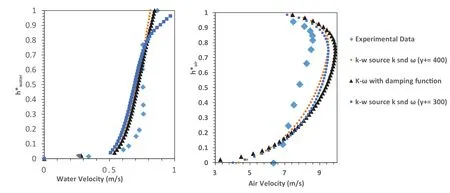
Fig.11.Velocity profile of water (left) and air (right) of Case 600 with employment of different source function.
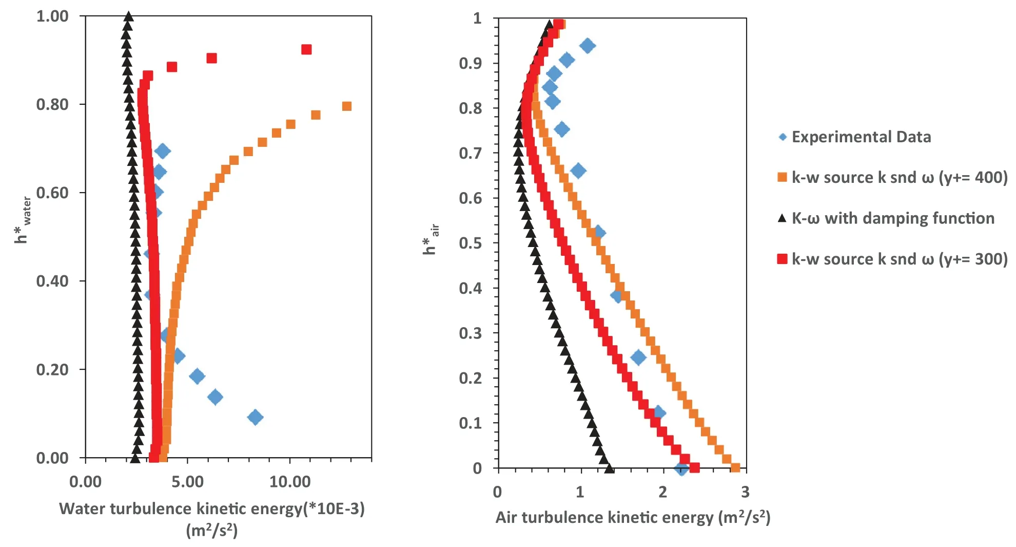
Fig.12.Turbulence kinetic energy profile of water (left) and air (right) of Case 600 with employment of different source function.
In addition to calculation of important parameter such as heat transfer coefficient, exact simulation of turbulence would change the prediction of flow pattern in horizontal flow.For this experiment, L–q diagram proposed by Brocchini and Peregrine [6]is employed to investigate the effect of the new turbulence model on flow pattern prediction.According to this diagram, turbulence length scale (L) and turbulence velocity (q) calculated by turbulence kinetic energy and dissipation rate is used to predict the surface shape of air and water flow.Fig.10 depicts the results ofLandqevaluation near the interface of case 400.If only the damping function is im- plemented at the interface, the shape of the interface would be categorized as flat surface or knobbly without any appearance of wavy flow in this region.In this model underestimation of turbulence kinetic energy leads to reduction ofLandqfor all point at the interface.But if the calculation ofLandqis repeated with implementation of both source functions, the flow regime change to wavy flow which agree to experiment reports.So, in addition to exact simulation of turbulence char- acteristics; consideration of turbulence kinetic energy source would change the predicted interface shape and consequently the closure model and coefficients in this region.
4.3.Wavy flow (case 600)
In the last scenario of Fabre et al.[12], the volumetric flow rate of air increases to 118.7 l/s with constant flow rate of water.Fig.11 shows the velocity profile of air and water.Similar to case 400, addition of turbulence source results in minor improvement in air section for each value of y+as the known boundary condition.Also Fig.12 shows the ef- fect of utilization of turbulence source function on turbulence kinetic profile near the free surface.Based on simulation re- sults, implementation of turbulence damping function leads to underestimation of turbulence in this region.Consideration of turbulence kinetic energy source function improves turbu- lence prediction according to Eq.(17).If y+increases to 400, the overestimation of turbulence kinetic energy occurs at the surface of air and water while selection of y+= 300 delivered better results similar to case 400 of experiment.
5.Conclusion
Simulation of smooth stratified flow (Case 250 of Fabre et al.[12]experiment) shows overestimation of turbulence kinetic energy in k–Ԑ and k–ωmodel without any modifica- tion.Also the results reveal a significant reduction of liquid mean depth causing increase of pressure drop and liquid ve- locity.Application of turbulence damping function improves the velocity profile and average pressure gradient decreases.This function would be obtained by consideration of an espe- cial boundary condition at air/water interface similar to wall and ignore of kinetic energy variation at the interface.As a result of damping function employment, the mean depth of water increases and turbulence kinetic energy decrease due to turbulence dissipation.
For wavy flow (Case 400 and 600 of (Fabre et al.[12]) ex- periment) application of damping function does not produce a good results especially in turbulence characteristics.In this flow regime, high gradient of velocity and turbulence kinetic energy change the boundary condition of turbulence equa- tions and the application of damping function, without any modification of kinetic energy leads to an underestimation of turbulence kinetic energy.So the new source function of tur- bulence kinetic energy was employed for wavy flow based on the evaluation of the transport equations.The results show that for appropriate boundary condition, the turbulence char- acteristics has good agreement with experimental data.Also, the prediction of flow regime in stratified flow depends on tur- bulence characteristics at air/water interface.The flow regime transition from smooth stratified to wavy flow due to air flow in ocean surface or rivers leads to different interfacial param- eters like drag force and heat transfer coefficient.In addition to flow regime, the characteristics of developed waves (e.g., wavelength, frequency) would be defined based on interfacial variables demonstrating the importance of interfacial turbu- lence flow parameters in ocean engineering.
For identification of the exact magnitude of turbulence source function, experimental investigation of two-phase strat- ified flow is a main tool needing more attention.It seems that the other experiments focusing on turbulence characteristics are need to depict the results of new turbulence model near the free surface.Turbulence velocity and turbulence length as two main parameters for interfacial heat transfer coefficient calculation depend on turbulence kinetic energy and dissipa- tion rate.Therefore, improvement of turbulence characteris- tics prediction is a key point for thermal system.On other hand proposed correlation of interfacial momentum and mass transfer in horizontal flow strongly depend on flow pattern.As shown in this paper, underestimation of turbulence at the in- terface would change the prediction of interface.The authors intend to survey the effect of the new turbulence function on heat and mass transfer coefficient in the next research.
 Journal of Ocean Engineering and Science2020年1期
- Journal of Ocean Engineering and Science的其它文章
- Power enhancement of pontoon-type wave energy convertor via hydroelastic response and variable power take-off system
- Application of SWAN model for storm generated wave simulation in the Canadian Beaufort Sea
- Invariant subspaces, exact solutions and stability analysis of nonlinear water wave equations
- Measurement and validation of tsunami Eigen values for the various water wave conditions
- Numerical simulation of air cavity under a simplified model-scale hull form
- Design methodology of permanent magnet generators for fixed-pitch tidal turbines with overspeed power limitation strategy
