Power enhancement of pontoon-type wave energy convertor via hydroelastic response and variable power take-off system
Zhi Yung Ty , , Ynji Wei
a Engineering Cluster, Singapore Institute of Technology, 10 Dover Drive, Singapore 138683, Singapore
b Faculty of Science and Engineering, University of Groningen, Nijenborgh 4, Groningen 9747AG, the Netherlands
Abstract
Keywords: Power generation enhancement; Pontoon-type wave energy convertor; Very large floating structure (VLFS); Hydroelastic response; Variable power take-off system; Genetic algorithm optimization.
1.Introduction
In order to mitigate the adverse effect of climate change, the International Panel on Climate Change (IPCC) has urged various sectors to reduce their dependency on fossil fuels.As a result, researchers and engineers have looked into other clean energy options such as wind, wave, solar or ocean ther- mal energy conversion as alternatives to our energy source.The global gross theoretical resource for wave energy has the highest energy density among the renewable energy sources [1]and it is estimated to be 3.7 TW, which is in the same order of magnitude as the global electricity consumption [2].Thus, this made it an attractive source of alternative energy as a replacement to the fossil fuels and resulted in the various ideation of wave energy convertors (WECs) that convert wave energy to electricity by using power take-off (PTO) systems.
The traditional types of WECs such as the point absorber, attenuator and terminator WECs generate energy via rigid body motion as waves hit on the structures.Recently, the at- tenuator WEC that is formed by interconnecting several float- ing modules with a series of PTO system equipped in/between the modules has gained popularity due to its high rated power and capture width ratio.The most well-known being the Pelamis WEC [3]which has a rated power of 750 kW and a capture width ratio of 7%.Other attenuator WECs such as the Ocean Grazer WEC ( www.oceangrazer.com) are proposed by researchers from the University of Gronigen to maximize the energy generation from wave via an interconnected array of floating modules connected by hinges.
Researchers have been looking into numerous ways to en- hance the performance of the WEC.One of the most common methods is to arrange the WECs in arrays [4–7]in order to maximize the power generation from the wave farm.To fur- ther enhance the performance of the wave farm, optimization technique has been performed to seek for the optimal array configuration for the wave farm [8,9].In addition, instead of using PTO systems with constant damping value, PTO with variable damping value has been proposed and it appears to improve the performance of the WEC array.This was demon- strated by Wei et al.[10]where the authors investigated the Ocean Grazer WEC with ten-hinged connected floating mod- ules where each module is connected by a PTO system with variable PTO damping.Their results showed that the perfor- mance of the WEC could be improved significantly through an appropriated PTO array configuration.Also, optimization on the individual PTO system could be performed in order to improve the overall power output, as suggested by de Backer et al.[11].
Another novel methodology to enhance the power output of the WEC is to use flexible material for the WEC that gen- erates energy via its flexible motion under wave action termed as the hydroelastic response.Haren and Mei [12]were among the first to propose an analytical model for a train of slender pontoons in a channel with rotational PTOs attached to the connecting hinges.Another example of a flexible-type atten- uator WEC is the Wave Carpet [13]proposed by researchers from the University of Berkeley as means to prevent erosion and protect the harbors by extracting energy from the waves to generate electricity.Other flexible type WECs are such as the Anaconda WEC [14], SBM S3 WEC [15]and Bombora WEC [16]which utilize the structural deformation in gen- erating energy.Zhang et al.[17]has also demonstrated the effect of structural flexibility on the power generation of two interconnected floaters.
It is to be noted that most of the aforementioned WEC are long flexible WEC modeled as beam [14,16 –18]]whereas the Wave Carpet WEC is a submerged plate-type WEC.So far, limited works on flexible plate-type WEC had been inves- tigated.For example, the Cyprus University of Technology has recently proposed the Water Level Carpet (WLC) WEC [19]which consists of four rectangular shaped floating mod- ules connected flexibly in two directions by connectors with PTO mechanisms where they found that the power produc- tion of the WLC obtains large meaningful values for wave frequencies close to the resonance of the generalized degrees of freedom.A novel type of WEC concept has been incor- porated in the very large floating structure (VLFS) for the use on ocean space utilization.Zhang et al.[20]addressed a flexible runway supported by an array of circular buoy with PTO and claimed that an optimal balance between maximiz- ing wave energy extraction and minimizing the movement of the runway can be achieved with proper stiffness and damp- ing coefficients of PTO.Another recent work by Tay [21]and Nguyen et al.[22]investigated a pontoon-type VLFS with an articulated plate that functions both as an antimotion device and a WEC.The author found that it is possible to generate an optimal amount of energy from the wave while keeping a high workability of the articulated plate in minimizing the hydroelastic response.
In view of the effectiveness in power generation enhance- ment via structural deformation for plate-type WEC, this pa- per aims to further study and understand the effect of allowing structural deformation in a pontoon-type WEC on the wave energy generation.The considered plate-type WEC is made up of multiple pontoon-type WECs floating on the surface of the water and comprises a grid of floating modules in- terconnected by line hinges where energy is generated via PTO systems.While a similar flexible raft-type WEC has been considered in [19], which is made up of a two-by-two floating modules, our study shall consider the effectiveness of different module configurations in power generation.Four different configurations of the pontoon-type WECs are con- sidered and described in detail in the following section, with each made up of different numbers of interconnected mod- ules.The effect of structural rigidity of the WEC is simu- lated using various Young’s modulus and structural length.In addition, a PTO system with variable PTO damping values is considered in order to quantify its effectiveness in enhanc- ing the power generation as compared to its counterpart of a constant/uniform PTO damping value.The genetic algorithm (GA) optimization scheme is used to seek for the optimal variable PTO damping that could maximize the power gen- eration of the WEC.The GA optimization technique [23], which is a search heuristic that mimics the process of natural selection and involves techniques inspired by natural evolu- tion, such as selection, mutation and crossover, is used as it enhances the computational time in meeting the objective function.The GA will converge over successive generations towards the global optimum via the aforementioned process and has been proven to be a robust tool for optimization in engineering problem [24].To the knowledge of the authors, the flexible pontoon-type WEC equipped with variable PTO systems for consideration of power enhancement has not been investigated elsewhere and the results presented shall provide insight on the effectiveness of power enhancement via these two methods.
2.Problem definition
The paper considers a pontoon-type WEC which consists of a grid ofNinterconnected floating modules, where each module is connected to each other by using(N−1)line hinge connectors (see Fig.1 ), i.e.Fig.1 (a) for Type-A withN= 12 (11 hinges), Fig.1 (b) for Type-B withN= 6 (5 hinges), Fig.1 (c) for Type-C withN= 4 (3 hinges) and Fig.1 (d) for Type-D withN= 1 (0 hinges).Each pontoon- type module has a lengthl, breadthB, depthhand is assumed to be made of an isotropic elastic material with a Young’s modulusEand mass densityρp.The module floats in a draftTwand on a constant water depth ofH.When connected to- gether, the pontoon type WEC has a total length dimensionL=N×l, breadthBand depthh.A total ofRnumbers of PTO system is attached to the WEC to generate energy via the rotational motions of the WEC.The PTO system is spaced at an equal interval ofin the horizontal direction (x−axis)andin the transverse direction (y−axis)as shown in Fig.1,therefore totaling a number ofM= 99 PTO systems as shown in Fig.1( a)–(d).

Fig.1.Pontoon-type WEC with (a) Type-A: N = 12 modules (b) Type-B: N = 6 modules (c) Type-C: N = 4 modules (d) Type-D: N = 1 module.
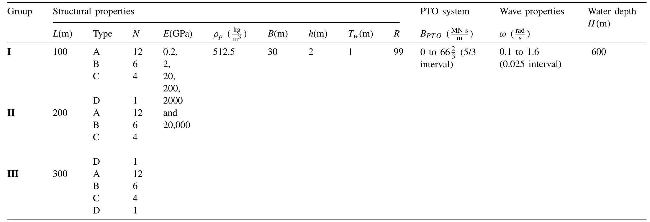
Table 1 Properties for different case studies considered.

Fig.2.Computation domain for pontoon-type WEC.
The properties of the pontoon-type WECs and wave con- dition are shown in Table 1.Three groups of pontoon-type WECs, each with differentLare considered, i.e.Group I withL= 100 m, Group II withL= 200 m and Group III withL= 300 m.For each group of the WEC, four types of WEC, i.e.Type-A, -B, -C and -D, each withNdiffer- ent numbers of module, are further considered and depicted in Fig.1 (a), (b), (c) and (d), respectively.It is to be noted that Type-A WEC has the highest number of line hinge con- nectors, whereas Type-B and -C have a reduced number of line hinge connectors.The Type-D pontoon-type WEC is a single module WEC and behaves like a continuous mat-like very large floating structures (VLFS).These different types of WECs are subjected to different elastic deformation behavior due to their different module lengthland Young’s modu- lusE, thus allowing the investigation of the effect of elastic deformation (i.e.structural rigidity) on the power generation of the WEC.In order to investigate the effect of structural rigidity on the wave energy generation, the WECs in Table 1 are modeled with six differentEvalues, i.e.E= 0.2 GPa , 2 GPa, 20 GPa, 200 GPa, 2000 GPa and 20,000 GPa.Also, it is to be noted that the total number of PTO systems are kept the same (R= 99 ) for all the WECs considered in Table 1 in order to ensure a fair comparison of the performance of the WECs.Studies will be carried out to investigate the ef- fect of variable PTO damping system in enhancing the power generation of the WEC as compared to its counterpart of a constant PTO damping system.A genetic algorithm optimiza- tion technique will be applied to seek for the optimal PTO damping following the scheme presented in [8].Two cases are considered in the GA optimization to seek for the op- timal variableBPTO, i.e.Case 1 where the GA optimization scheme is applied to all theBPTOin the pontoon-type WEC and Case 2 where the GA optimization scheme is applied to theBPTOattached to the line hinge connector only.It is noted here that for the variable PTO system, theBPTOare assumed to vary along thex−axis direction but are kept constant for each line connector (along they-axis direction) in order to reduce the computation time.The scheme will be explained in detail in Section 3.6.
The pontoon-type WEC is subjected to a series of regular waves with a constant wave amplitude 2A.The wave frequen- ciesωrange from 0.1 rad/s to 1.6 rad/s with an interval of 0.025 rad/s where the regular waves approach the WEC at the head sea direction.The WEC is assumed to operate in a deepwater condition where the effect of seabed on the struc- tural motion is negligible.The particulars and properties of WEC models are given in Table 1.In order to facilitate the discussion, the pontoon-type WEC will be referred to by their Group and Type as summarized in Table 1.For example, a Group I Type-A WEC refers to the 100-m long pontoon-type WEC interconnected withN= 12 floating modules.
3.Mathematical formulation
The response of the pontoon-type WEC is computed by us- ing the hybrid boundary element–finite element method (BE–FE) developed in MATLAB® where the WEC is modeled as an isotropic plate whereas the fluid is assumed to be inviscid and incompressible and its flow assumed to be irrotational.The globalx−,y−,z−axes have the positive direction ac- cording to the right hand rule and the origin is located on the center of the WEC, with thex−yplane located at the free surface, i.e.z= 0.Fig.2 shows the computational domain of the WEC, where the WEC is assumed to float on the free surface with a constant water depthH.In the BE–FE method, the water domain is represented byΩ, the wetted surface of the WEC by the boundarySH, the seabed bySB, the free surface bySFand the surface at the distance far away from the WEC asS±∞.The governing equations for the water and plate as well as the formulation for generated power from the WEC and GA optimization scheme will be presented in the subsequent sections.
3.1.Water domain

Based on the potential flow theory, the fluid motion may be represented by a velocity potentialΦ(x,y,z,t).We consider the water to oscillate in a steady-state harmonic motion with the circular frequencyω.The velocity potentialΦ(x,y,z,t) could be expressed into the following form:
The velocity potentialφ(x,y,z) can be expressed as the sum of the diffracted potentialφDand radiated potential by using the linear potential theory, i.e.

where the second term in the right hand side of Eq.(2) is the radiated potential expressed as a series of product ofPnum- bers of modal amplitudesζland the unit-amplitude radiated potentialφl.
The single frequency velocity potentialφ(x,y,z) must sat- isfy the Laplace equation [25],

and the boundary conditions on the surfaces as shown in Fig.1 , which are given as follows [25]:

wherenis the unit normal vector to the surfaceS.The de- flection of the pontoon-type WECwin ( 4 ) is described in Section 3.2.It is noted that the hull wetted surfaceSHpre- sented in Fig.2 is divided into the bottom hull wetted surfaceSHBand the side hull wetted surfaceSHS, i.e.SHB∪SHS∈SH.The wave velocity potential must also satisfy the Sommerfeld radiation condition at the artificial fluid boundary at infinityS∞as (x,y) → ∞ [25]

wherekandφinare the standard wave number and incident velocity potential as found in [26]

Fig.3.Figure showing w and ψ x of Mindlin plate theory.
The Laplace Eq.(3) together with the boundary conditions (4) –(8) on the surfaceSare transformed into a boundary in- tegral equation (BIE) by using the Green’s Second Theorem via a free surface Green’s function.Since the Green’s func- tion satisfies the surface boundary condition at the free water surfaceSF, the seabedSBand at the infinityS∞, only the wetted surface of the bodiesSHneed to be discretized into panels so that the boundary element method could be used to solve for the diffracted and radiated potential.For details on the Green’s function used in solving the BIE, refer to [26].
3.2.Structure domain
The pontoon-type WEC on the other hand is modeled as a solid plate by using the Mindlin thick plate theory [27,28].The solid plate is simplified to be perfectly flat with free edges and the plate material is commonly assumed to be isotropic and obeys Hooke’s Law.The WEC is restraint from mov- ing in the horizontalx−yplane directions by station keep- ing system and only allowed to move vertically.Hence, the hydroelastic response of the pontoon-type WEC could be de- scribed by the deflectionw(x,y), the rotation about they-axisψx(x,y) and the rotation about thex-axisψy(x,y) as shown in Fig.3.The governing equations for the Mindlin plate theory are given as follows:

whereG=E/[ 2(1 +ν)]is the shear modulus,κ2the shear correction factor taken as 5/6,ρpthe mass density of the plate,hthe thickness (i.e.depth) of the plate,D=Eh2/[ 12(1 −ν2)]the flexural rigidity,Ethe Young’s mod- ulus andνthe Poisson ratio.The pressurep(x,y) in Eq.(9) comprises the hydrostatic and hydrodynamic pressure.The boundary conditions at the free edges of the floating plate are
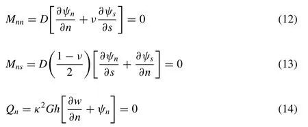
whereMnn,MnsandQnare the bending moment, twisting moment and shear force, respectively.sandndenote the tangential and normal directions to the section of the plate, respectively.
3.3.Continuity equations for hinge connector with PTO system
The continuity equations for the interconnected plate at the hinge connector with PTO dampingBPTOlocated at(xc)r=1,2,...,Rare
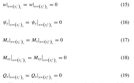
These continuity requirements can be implemented into plate elements along the line connection using the standard finite element method.Note that(x−c)rand(x+c)rdenote the location at the left and right hand side of therth PTO sys- tem, respectively.Power take-off system is attached at the connector to convert the kinetic energy of the interconnected plate due to wave action to electricity.This is modeled as damper withBPTOalong the line hinge connector, i.e.y-axis atx=(xc)r.
3.4.Equation of motion for water-plate model
The coupled water-plate problem is solved by using the coupled BE–FE scheme, where the Laplace equation together with the water boundary conditions are solved using the boundary element method whereas the plate equation and its boundary conditions using the finite element method.Due to space constraint, details of the solution scheme are not presented here, but interested readers can refer to the de- tails in [26].ForNnumbers of interconnected modules in the pontoon-type WEC, the equation of motion of modulepdue to moduleqis written as


It is noted here that for each node along the line connector, there will be five degrees of freedom, namelyandThe positive ( + ) and negative ( −) signs denote the right hand side and left hand side of the node in the line connector.
3.5.Generated power from anti-motion device
The rotation of the hinge connectorψycalculated from (21) can be used to compute the total average generated powerPaof the anti-motion device over the range of wave frequencyωconsidered in the regular wave by using the following expression

The total average generated powerPais then expressed as capture width (CW) [29]by normalizing with the wave power resourcePresource(24) in order to quantify the efficiency of the anti-motion device in generating wave energy.

TheCWis the width of a wave crest that contains the samePaas extracted by a WEC and theCWhas to be as large as possible for the anti-motion device to be effective in generating wave energy.The wave power resourcePresourcein (23) is given as [30]whereρis the density of sea water,gthe gravitational accel- eration,Tthe wave period andHthe significant wave height.

3.6.Seeking optimal B PTO using GA optimization scheme
The optimal constant and variable PTO damping for the pontoon-type WEC are sought by using an in-house GA op- timization code developed in MATLAB®.The objective func- tion is to achieve maximum absorbed powerPa(22) orCW(23) which indicates the maximum power absorption from the waves.The variables used to satisfy the objective func- tion are the PTO dampingBPTOranging from 0 MN s/m toMN s/m with 40 intervals, hence considering a possibil- ity of 41 PTO damping values for each PTO system.Note that the maximum range of the variables (BPTO) is set toMN s/m in the optimization process as the effect of theBPTOon the hydroelastic response becomes negligible when the value is very large.It is noted that the maximum value ofMN s/m is obtained by normalizing the maximumBPTOof 20 GMN s by the structural lengthLof 300 m.
Without the GA optimization scheme, the total possible combination of theBPTOis denoted byNT, whereNTis given as

whereNLis the number of PTO considered in the pontoon- type WEC, i.e.NL=R= 99.Eq.(25) will produce a total of 4199possible combinations of PTO damping for the con- sidered WEC, which is obviously impractical due to its large computational cost involved.In order to devise a more practi- cal optimization process, theBPTOalong they−axis direction is varied but kept constant along thex−axis direction, thus reducingNLin (25) to 11 for the pontoon-type WEC con- sidered here.The assumption made here is practical from the engineering point of view, as having a constantBPTOalong they−axis direction, i.e.along the line hinge, will result in symmetrical structural deflection about thex−axis under head sea condition, thus inducing lower stress resultants as com- pared to its asymmetrical counterpart.Besides, having a uni- formBPTOvalue along the hinge is more practical as it will ease the installation of the PTO system.WithNL= 11 ,NTis reduced to 4111≈5.5 ×10¹⁷but is still computationally ex- pensive without the GA optimization scheme.
In order to reduce the computational time to seek for the optimalBPTO, the GA optimization scheme is utilized where it is divided into two steps as depicted in Fig.4 , i.e.
(i) Step 1: Generating an initial population ofNR
(ii) Step 2: Applying GA optimization scheme to the initial population to seek for the optimalBPTO.
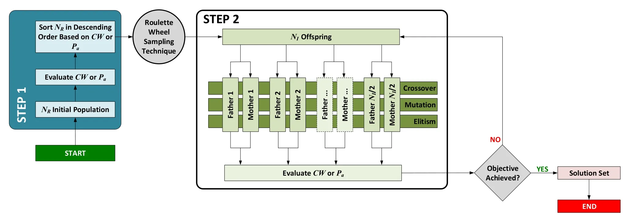
Fig.4.Flow chart of GA optimization scheme.
In Step 1, the initial population ofNR= 500,000 different combination ofBPTOis generated by using a bias distribution.In Step 2,NIindividuals having the highest fitness values in terms of thePaorCWare then selected from the gener- atedNRby using the roulette wheel sampling technique [31].Next,NIsets of parents (father and mother) are randomly selected from theNIindividuals for the crossover and mu- tation operations in order to createNIoffspring for the next generation.In addition, the individual with the best fitness value in the current generation are kept for the next gener- ation, and this individual is known as the elite child.This process of crossover, mutation and elitism will continue until the objective function is met, i.e.the maximumPaorCWhas converged.The convergence criteria for the maximumPaorCWis 0.01%.It is to be noted that although increasingNIincreases the computational time, it ensures a faster com- putational time in achieving convergence for thePaorCW, vice-versa.For the case study,NI= 50 is selected as this number is sufficient to ensure a faster convergence based on the authors’ computational resource.It is also noted here that the parent are known as the DNA whereas theRnumbers ofBPTOare known as the chromosomes in the GA optimization scheme.
The chromosomes will be converted into binary numbers of 20 bits for the crossover and mutation processes.The crossoverCcand mutationCmprobabilities are taken as 0.2 and 1.0, respectively.This implies that the crossover process between the two DNAs applies only to 20% of the chromo- somes whereas the mutation process only applies to all the chromosome of the best fit.The choice ofCm= 1.0 will be explained in Section 4.2.
4.Validation of results
4.1.Hydroelastic response for interconnected structure
The solver for the equation of motion for the water-plate model (20) is developed in MATLAB®.The code for the hydroelastic analysis is validated with the results of the VLFS presented by Yago and Endo [32]and Fu et al.[33]in the subsequent sections.
4.1.1.Convergencestudy
A convergence study is performed to investigate the ef- fects of the boundary discretization on the convergence of thehydroelastic response of the VLFS presented in [33].The de- tails of the numerical model used are presented in Table 2 and the complianceχof the hydroelastic response is defined as

Table 2 Details of floating model used for convergence study.

The number of elements per wavelength is used as the basis for the discretization of the plate system.In the present convergence study, the number of elements per wavelengthεis taken as 10, 15, 20, and 25; and the number of plate natural modesNmis taken as 10, 15, 20, and 25.The results are summarized in Table 3 which shows that the compliance of the two-floating plate system for several combination ofεandNm.
As can be seen in Table 3 , the complianceχconverges whenε= 25 andNm= 20.It is noted that the convergence criteria is 1.5% forεand 1.0% forNm.Therefore,ε= 25 andNm= 20 are considered as the optimal combination of the two parameters for all wavelengths considered, and will be used in the subsequent analyses.
4.1.2.Comparisonwithexistingresults
The validity and accuracy of the present method for solv- ing the floating plate problem with mechanical line joints is established by comparing the hydroelastic responses com- puted by the present method with the experimental results ob- tained by Yago and Endo [32]and the numerical results by Fu et al.[33].The input data for the floating plate problem used by the aforementioned researchers are given in Table 2 where the VLFS considered is a two 150-m long intercon- nected floating modules connected by using a mechanical line hinge to form a VLFS with 300 m in total length.

Fig.5.Hydroelastic response along the center line of VLFS in Table 2 under (a) λ/L = 0. 2 (b) λ/L = 0. 4 (c) λ/L = 0. 6 (d) λ/L = 0. 8.Headsea condition.

Table 3 Compliance for several combinations of εAND N m for the numerical model presented in Table 1.
The comparison of the hydroelastic response along the cen- terline of the VLFS between the present numerical results with those found in [32]and [33]are presented in Fig.5.The good agreement between experimental and numerical re- sults for the continuous structure validates the correctness and accuracy of the present method for evaluating the hydroelas- tic response of the VLFS with line connectors.The numerical results of the hinged-connected VLFS also show good agree- ment between the present method and those published in [33].
4.2.GA optimization scheme
In order to validate the reliability of the present GA op- timization scheme, the results obtained from the GA opti- mization scheme is compared with their counterparts obtained from the parametric analysis.As the pontoon-type WECs pre- sented in Table 1 are too large to run on the parametric anal- ysis, a much simpler pontoon-type WEC is considered in the validation exercise where the WEC is connected by only a one-line hinge connector with PTO attached to it.The lengthLand breadthBof the pontoon WEC are taken as 300 m and 60 m, respectively (i.e.Group III in Table 1 ).Two wave peri- ods are considered here, i.e.T= 6.2026 s andT= 8.7668 s , which corresponds toλ/L= 0.2 and 0.4, respectively.In the parametric analysis, theBPTOis assumed to range from 0 toMN s/m with an interval ofMN s/m , hence re- quires an execution ofNT= 500,000 operations.It is noted that the normalized maximumMN s/m when multiplied with the lengthL= 300 m yields a maximumBPTOof 500 GN s at each line connector.TheBPTOthat produces the highest absorbed powerPaor capture width ratioCWis taken as the optimal PTO damping.

Table 4 Computational time for parametric analysis vs GA optimisation scheme.
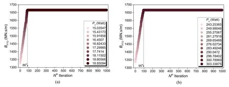
Fig.6.Evolution of B PTO to achieve maximum absorbed power P a using GA optimization scheme for (a) λ/L = 0. 2 and (b) λ/L = 0. 4.C m = 1 . 0 and C s = 0. 2.
On the other hand, the GA optimization scheme is used to obtain the optimal damping following the two steps given in the Section 3.6.In step 1, the initial populationNRis taken as 1% of theNT, i.e.NR= 5,000.These 5000 initial populated samples are then fed into the GA optimization scheme to obtain the optimalBPTO.
The computational time for both the parametric analysis and GA optimization scheme is compared in Table 4.It can be clearly seen that the number of simulations required for the GA optimization scheme is far lesser than its counterpart for the parametric analysis.As a result, the computational time for the GA optimization scheme is 87.5% faster than the parametric analysis, when running on an Intel® CoreTMi7-5600U CPU@2.60 GHz machine.This presents a signifi- cant enhancement in the computation time by using the GA optimization scheme and will be useful for largerNTas pre- sented in the following sections.It is to be noted that the optimalBPTOobtained from the parametric analysis and the GA optimization scheme are the same (refer to Fig.6 ), thus confirming the reliability of the present GA code in seeking the optimalBPTO.The evolution of theBPTOto achieve the maximum absorbed powerPafor bothλ/L= 0.2 and 0.4 are presented in Fig.6 (a) and (b), respectively.The various color tones denote the different absorbed powerPaof the WEC cor- responding to the respectiveBPTOin they-axis.ThePain the legends changes in ascending order denoted by the lighter to darker tone.It can be seen that the present GA optimization scheme successfully achieves the optimalBPTOat the 86th and 95th iteration.
In the GA optimization scheme presented in Fig.4 , the crossover and mutation probability have to be set in order to accelerate the convergence of the GA process in obtain- ing the optimalBPTO.Therefore, a convergence test is con- ducted in Fig.7 for the same pontoon-type WEC considered in the validation exercise for two differentCm, i.e.Cm= 0.5 andCm= 1.0.As can be seen clearly, the GA optimization scheme running atCm= 1.0 accelerates the convergence pro- cess in seeking the optimalBPTO.It is noted thatCm= 1.0 implies that all the chromosome (i.e.BPTO) is selected to be mutated at each iteration in the GA scheme.
5.Results and discussion
5.1.Effect of hydroelastic response
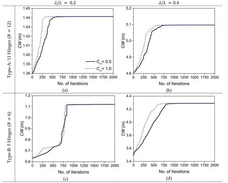
Fig.7.Convergence test for Group III ( L = 300) pontoon-type WEC under GA optimization scheme for two different C m.C s = 0. 2.

Fig.8.Capture width CW for Group I Pontoon-type WEC ( L = 100 m) under different Young’s Modulus E.

Fig.9.Capture width CW for Group II Pontoon-type WEC ( L = 200 m) under different Young’s Modulus E.

Fig.10.Capture width CW for Group III Pontoon-type WEC ( L = 300 m) under different Young’s Modulus E.
Figs.8 –10 show theCWof Groups I(L= 100 m), Group II(L= 200 m)and Group III (L= 300 m) pontoon-type WEC, respectively.Six different Young’s mod- uli, i.e.E= 0.2,2,20,200,2000,20000 GPa with a constantBPTO= 600 kN s/m are considered.The pontoon-type WEC is subjected to wave frequenciesωranging from 0.1 rad/s to 1.6 rad/s with wave approaching from the headsea.Fig.8 shows that the 100-m pontoon-type WEC is very effective in generating wave energy when it is connected with the most number of hinges (Type-A).This results in shorter modules rotating in rigid body motion and thus generating more en- ergy when subjected to wave action.Also, theCWor thePado not change with respect to the varying structural flexural stiffness, which depends on the Young’s modulusE.How- ever, when the pontoon-type WEC gets longer as presented in Figs.9 and 10 , i.e.L= 200 m and 300 m, respectively, it can be seen that greater energy can be generated depend- ing on the Young’s modulusEof the pontoon-type WEC.It is observed that more energy can be generated by the WEC when each module in the pontoon-type WEC deforms flexi- bly, with the most energy generated when the module is the most flexible (i.e.E= 0.2 GPa ).In addition, it is interest- ing to find out that the amount of energy being generated increases with the reduction in the number of hinges in the WEC.This is because a reduced number of hinges results in longer connected modules, and thus the structures deform in a flexible manner under wave action.As a consequence, the 200-m and 300-m long pontoon-type WEC have the highest power generation when the WEC is connected by only one hinge withE= 0.2 GPa.
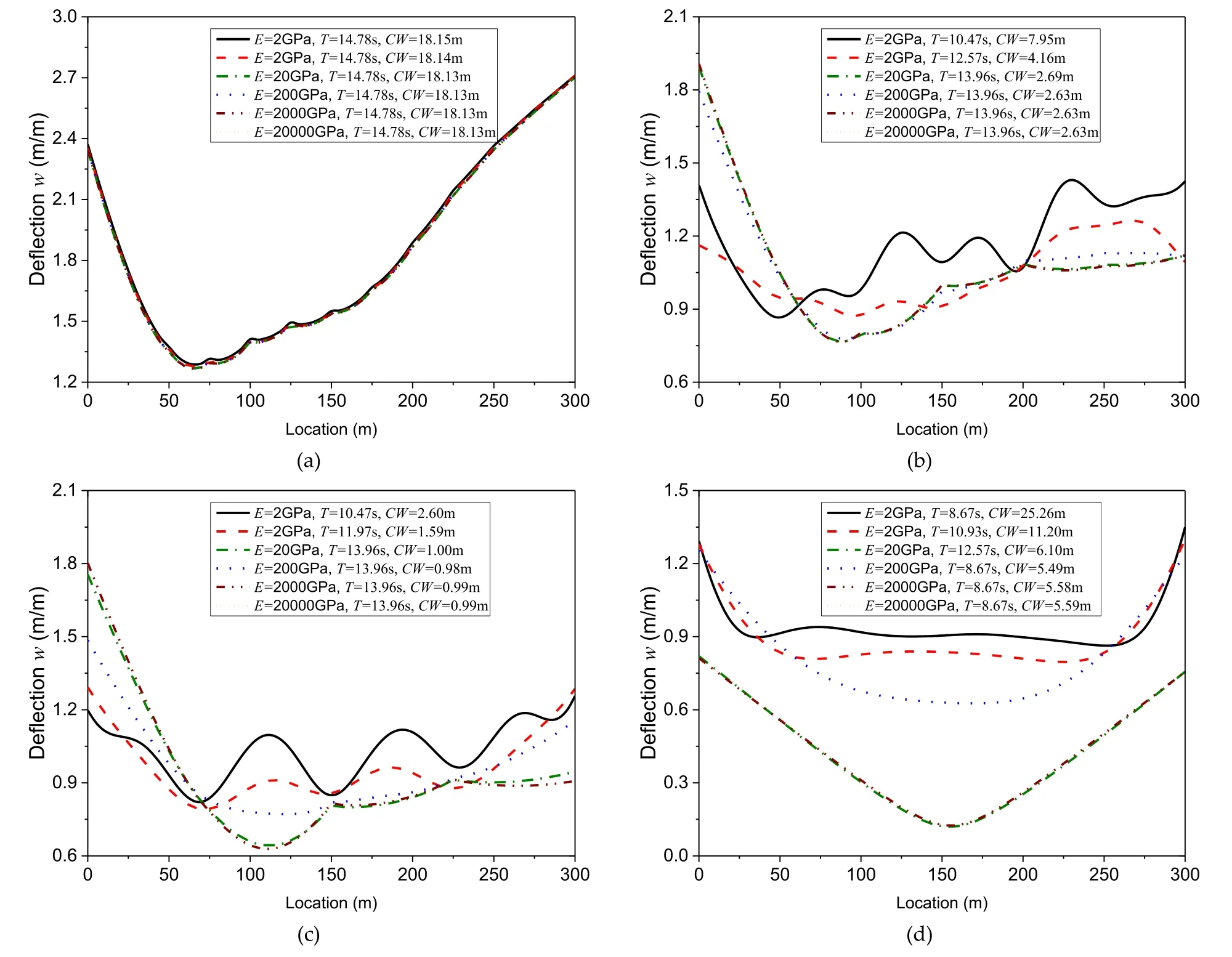
Fig.12.Hydroelastic response for Group II ( L = 200 m) pontoon-type WEC with (a) Type-A: N = 12 modules (b) Type-B: N = 6 modules (c) Type-C: N = 4 modules (d) Type-D: N = 1 module.
The comparisons of the hydroelastic response of the Group I pontoon-type WEC for different numbers of hinges, i.e.Type-A: 11 hinges, Type-B: 5 hinges, Type-C: 3 hinges and Type-D: no hinges are presented in Fig.11.The deflection is measured along the centerline of the WEC and the structure is subjected to a headsea condition.In each subfigure, the six different lines represent the hydroelastic responses of the WEC with differentEwhen subjected to their corresponding wave periodsTthat produce the maximumCW.It can be seen that the influence of the Young’s modulus is negligibly small for the WEC connected by large numbers of connec- tors, i.e.Type-A and Type-B; but its effect increases when the pontoon-type WEC is connected by smaller numbers of mod- ule, i.e.Type-C and Type-D.It is also observed clearly that theCWfor a continuous pontoon-type WEC (Type-D) is able to generate more energy than its counterpart with connectors.This finding denotes that a significant cost saving could be achieved due to the shorter installation time and the smaller number of connectors needed.In addition, it also saves on material cost as the WEC could be manufactured with lesser material to allow for flexible deformation provided that the stress resultants on the structure are within the stipulated al- lowable stress limit to ensure the safety and robustness of the structure.
Similarly, the hydroelastic responses for the 200-meter and 300-meter pontoon-type WEC are presented in Figs.12 and 13 , respectively.As the length of the WEC becomes longer, the effect of the Young’s modulusEon the motion of the WEC becomes significant.According to Suzuki’s et al.[34]definition of a VLFS, the hydroelastic response is only dominant when the following two ratios are larger than 1.0:
i Structural length/wavelength (l/λ)
ii Structural length/characteristic length (l/λc)
The characteristic lengthλcis given as

whereDis the flexural rigidity given asD=Eh3/12 andkcis the spring constant of the hydrostatic restoring force.By using the ratios given in (i) and (ii) above, this could explain the reason that some of the pontoon-type WECs behave like a rigid body under wave action whereas others in a flexible motion.For example, this can be shown clearly in Fig.13 (d) where the WEC withE= 20,000 GPa moves in a rigid body motion.Therefore, it is always important to check on these two ratios when designing the pontoon-type WEC.
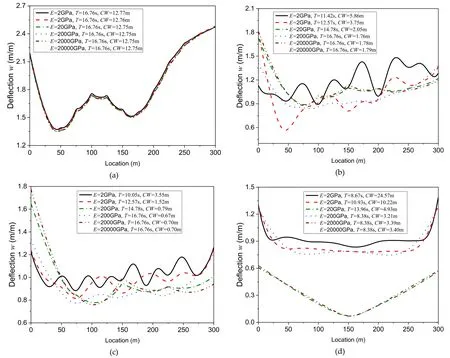
Fig.13.Hydroelastic response for Group II ( L = 300 m) pontoon-type WEC with (a) Type-A: N = 12 modules (b) Type-B: N = 6 modules (c) Type-C: N = 4 modules (d) Type-D: N = 1 module.
5.2.Effect of non-uniform optimized PTO damping
In addition to allowing for certain degree of structural de- formation in the pontoon-type WEC, the energy generation from the pontoon-type WEC could be further enhanced by us- ing a non-uniformly distributed optimal PTO damping, termed also as variable PTO system.In order to seek for the opti- mal PTO damping, the GA optimization scheme as outline in Section 3.6 is used.The Group III(L= 300 m)pontoon- type WEC subjected to two different wavelength-to-structural length ratios, i.e.λ/L= 0.2 and 0.4 is used to demonstrate the power enhancement of the pontoon-type WEC.
By using the GA optimization scheme as given in Section 3.6 , with an initial population ofNR= 500,000,Cc= 0.2 andCm= 1.0, the evolution ofBPTOfor Group III pontoon- type WEC to achieve the optimalBPTOis plotted in Fig.14.Each subfigure denoted by Fig.14 (a)–(f) represents the WEC connected by different numbers of connection joints and sub- jected to regular waves of two differentλ/L.The optimal damping value at each PTO system that results in the maxi- mumCWis presented in each subfigure.It can be seen that by using the GA optimization scheme, the optimal non-uniform distributed PTO damping at each line connector that produces the maximum power could be obtained.Fig.14 shows that a combination of the minimumBPTO(i.e.0 MN s/m) and max- imumBPTO(i.e.MN s/m ) for the pontoon-type WEC could be used to achieve the maximumCW.However, the non-uniform distributed optimalBPTOcould be in the range between these minima and maxima values such as for the Type-A pontoon-type WEC, where the WEC is connected by more connection joints.
By focusing on the pontoon-type WEC of Group III Type- A, the evolution of theBPTOis presented in Fig.15 for four differentλ/L, i.e.λ/L= 0.2,0.4,0.6 and 0.8.It can be seen from Fig.15 (a) that the maximumCWcan be achieved by us- ing a different combination ofBPTOwhere the optimalBPTOfor each PTO system does not necessary be the minimumBPTO(0 MN s/m) or maximumMN s/m ) consid- ered in Table 1.Fig.15 also shows that the optimalBPTOvalue could be a combination of the minimum and maximumBPTOto achieve the maximum power generation when the WEC is subjected to large wavelength.
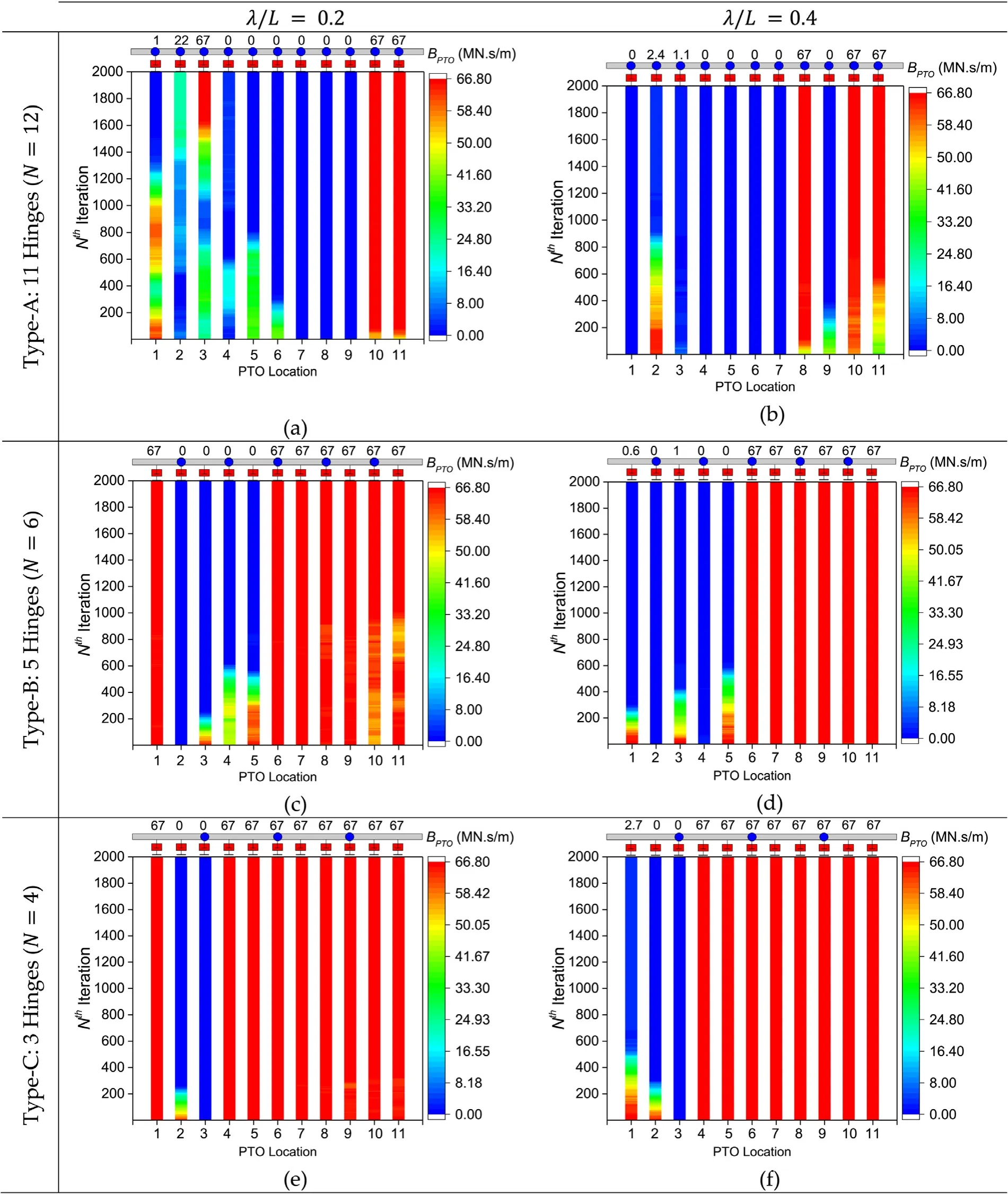
Fig.14.Evolution of PTO damping B PTO for Group III ( L = 300.m) pontoon-type WEC under GA optimization scheme.

Fig.15.Evolution of PTO damping B PTO for Group III ( L = 300 m) Type-A ( N = 12 modules) pontoon-type WEC under GA optimization scheme.
In order to visualize the hydroelastic response of the pontoon-type WEC under uniform and non-uniform optimalBPTO, the deflection along the centerline of the WEC is plot- ted in Fig.16 for the Group III Types-A–C pontoon-type WEC.A comparison of the deflection is made between the WEC connected by variable PTO system with that by uniform PTO system.It can be seen clearly from Fig.16 that theCWof the non-uniform optimalBPTOcounterpart is greater than that predicted by the uniform counterpart.However, the dif- ference is more obvious for Type-A pontoon-type WEC due to the greater magnitude of rotational motion in the WEC.Similarly, the same results are plotted forλ/L= 0.4,0.6 and 0.8 in Figs.17 , 18 and 19 , respectively, and similar obser- vation can be made on theCWof the WEC.An interest- ing point to make when comparing the results presented in Figs.16 –19 is that the difference of theCWfor the WEC connected by variable PTO system with its uniform coun- terpart becomes greater when the wavelength increases.This suggests that the optimal variable PTO system is more effec- tive when the WEC is subjected to regular waves of longer wavelengths due to the larger magnitude of hydroelastic re- sponse.In addition, theCWfor the WEC is found to increase with the increase in wavelength.
In Fig.20 , a comparison of the hydroelastic response of the pontoon-type WEC with Types-A, -B and -C pontoon- type WEC with the continuous pontoon-type WEC (Type- D) is presented.These WECs are subjected to four differentλ/Lranging from 0.2 to 0.8, with an interval of 0.2.It is interesting to note that the continuous pontoon-type WEC is the most effective among the four in generating wave energy when it is equipped with optimal variable PTO system.The optimalBPTOobtained from the GA optimization scheme in this case falls in the higher range of theBPTOconsidered in Table 1 to achieve the maximumCW.
6.Conclusion
The pontoon-type WEC was considered and the coupled finite element-boundary element method was used to solve for the hydroelastic response of the WEC.The GA optimiza- tion scheme was utilized in seeking the optimal PTO damp- ing of the variable PTO system, where the objective func- tion was to achieve a maximum capture widthCWor the absorbed powerPaof the WEC.Three WEC lengths were considered, i.e.L= 100 m,200 m and 300 m, which were categorized as Group I, II and III, respectively.Four different numbers of interconnected modules, i.e.N= 12,6,3 and 1 were then considered for each group of WEC, which were termed as Types-A, -B, -C and -D, respectively.The two ob- jectives of the paper were successfully achieved, that is to en- hance the power generation of the WEC via certain allowance of structural deformation and installation of variable PTO system.

Fig.16.Hydroelastic response for Group III pontoon-type WEC under λ/L = 0. 2 with uniform and non-uniform optimized PTO damping.

Fig.17.Hydroelastic response for Group III pontoon-type WEC under λ/L = 0. 4 with uniform and non-uniform optimized PTO damping.

Fig.18.Hydroelastic response for Group III pontoon-type WEC under λ/L = 0. 6 with uniform and non-uniform optimized PTO damping.

Fig.19.Hydroelastic response for Group III pontoon-type WEC under λ/L = 0. 8 with uniform and non-uniform optimized PTO damping.
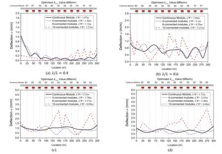
Fig.20.Comparison of hydroelastic response for Group III continuous pontoon-type WEC with 4-, 6- and 12-connected modules under their respective optimized B PTO for (a) λ/L = 0. 2 and (b) λ/L = 0. 4 (c) λ/L = 0. 6 (d) λ/L = 0. 8.
In the investigation on the effect of structural deforma- tion, i.e.structural rigidity, on the power enhancement of the pontoon-type WEC, it was found that greater energy could be generated when the interconnected module in the WEC is allowed to deform under wave action.The effect of struc- tural deformation is even larger when the structural length increases and when the number of interconnected hinge re- duces.It is interesting to note that a continuous pontoon-type WEC without any hinge connector is able to generate the greatest amount of energy among the cases considered in the study.The effect of Young’s modulus was found to be sig- nificant when the Group II and III pontoon-type WECs are connected with smaller amount of hinge connectors.This is because lesser number of hinge connectors imply longer inter- connected floating modules and thus higher structural defor- mations under wave action.The results presented show that a significant saving in cost, material and connector installation could be achieved for the pontoon-type WEC and at the same time producing high amount of electricity, provided that the structural integrity of the WEC is preserved.
In the investigation on the effect of utilizing variable PTO system on the power enhancement of pontoon-type WEC, it was found that in some cases, the maximum power gener- ation could be achieved by merely utilizing a combination of minimum and maximumBPTOthat were considered in the case study.However, it was also found that the optimal non- uniformBPTOfor the Type-A pontoon-type WEC comprises a combination ofBPTOthat falls in between the minimum and maximumBPTOconsidered.These optimalBPTOwas success- fully sought by using the GA optimization scheme.The effect of variable PTO system was found to be significant with the increase in the number of hinge connectors and wavelengths.This is due to the greater magnitude of rotational motion in the WEC.
In summary, it was proven from the study that the power generation of the pontoon-type WEC can be enhanced by allowing the structure to deform flexibly under wave action as well as by installing a series of variable PTO system in the pontoon-type WEC.This outcome will be useful to academia and industry working on achieving the power enhancement of WEC.
 Journal of Ocean Engineering and Science2020年1期
- Journal of Ocean Engineering and Science的其它文章
- Application of SWAN model for storm generated wave simulation in the Canadian Beaufort Sea
- Invariant subspaces, exact solutions and stability analysis of nonlinear water wave equations
- Measurement and validation of tsunami Eigen values for the various water wave conditions
- New turbulence modeling for air/water stratified flow
- Numerical simulation of air cavity under a simplified model-scale hull form
- Design methodology of permanent magnet generators for fixed-pitch tidal turbines with overspeed power limitation strategy
