
Operator-Based Robust Nonlinear Free Vibration Control of a Flexible Plate With Unknown Input Nonlinearity
2020-05-22 02:56GuangJinandMingcongDeng
Guang Jin and Mingcong Deng
Abstract—In this paper, a robust nonlinear free vibration control design using an operator based robust right coprime factorization approach is considered for a flexible plate with unknown input nonlinearity. With considering the effect of unknown input nonlinearity from the piezoelectric actuator, operator based controllers are designed to guarantee the robust stability of the nonlinear free vibration control system. Simultaneously, for ensuring the desired tracking performance and reducing the effect of unknown input nonlinearity, operator based tracking compensator and estimation structure are given, respectively. Finally, both simulation and experimental results are shown to verify the effectiveness of the proposed control scheme.
I. Introduction
RECENTLY, with the development of smart materials,smart material based actuators have attracted considerable attention of the researchers. The smart actuator has been proposed are piezoelectric element, shape memory alloy, magnetic fluid actuator, and so on. The piezoelectric material can not only convert electrical energy to mechanical energy but also can convert mechanical energy to electrical energy caused by pressure. Therefore, the piezoelectric material can be used as a sensor for its piezoelectric effect, also, it can be used as an actuator as to its reverse piezoelectric effect [1]. In[2], the active vibration control scheme of the cantilever beam was performed using a distributed actuator. The thin plate that was excited the vibration by using piezoelectric patches was analyzed in [3]. Where, the existence of nonlinear properties of the piezoelectric actuator is always ignored, treated systems linearly. However, this method causes errors in dynamic response and output’s displacement that may result in unstable. Therefore, when using the piezoelectric actuator, we need to consider the hysteresis nonlinearity.
In recent years, a nonlinear control method has been proposed based on robust right factorization [4]–[6]. Also,there are some papers considering the robust control designing and operator-based control designing for nonlinear control systems [7]–[13], the hysteresis nonlinearity of piezoelectric actuator, and perturbed plants with hysteresis based on operator theory [14], [15]. In this paper, we consider a type of free vibration that the vibration of a structure that occurs at its eigenfrequency, as opposed to forced vibration. In [1], the operator based two loop nonlinear forced vibration control method for a flexible plate with the piezoelectric actuator has been proposed. Also, considering the free vibration on the flexible plate, the method of [1] is confirmed in [16] and [17]by simulations and experiments, respectively. However, the operator based compensator of the outer loop only used proportional control. Therefore, it is difficult to ensure the desired vibration control performance of the flexible plate. In[15], operator based free vibration control for an aircraft vertical tail with piezoelectric actuator has been proposed.And numerical simulations were performed to verify the proposed control system. But, the effectiveness of the designed control system was not confirmed by experiment. In[18], regarding the fatigue of the vertical tail caused by vibration, free vibration control of the vertical tail has been proposed. Also, considering the hysteresis nonlinearity from the piezoelectric actuator, Prandtl-Ishlinskii (P-I) hysteresis model was used. Then, the considered a bounded uncertainty part of the P-I hysteresis model was used in the nonlinear tracking compensator to compensate for the piezoelectric actuator with hysteresis nonlinearity. However, an assumption is required that internal signals are known ones. And, the bounded uncertainty part of the P-I model had to be known.
In this paper, a new robust nonlinear free vibration control design scheme is proposed. The designed free vibration control system could guarantee robust stability of the nonlinear system by operator theory. In the design scheme,operator based tracking compensator and estimation structure are designed to ensure desired tracking performance and to reduce the effect of unknown input nonlinearity, respectively.
This paper is organized as follows. The experimental devices of this study, hysteresis model of the piezoelectric actuator, and operator theory are introduced in Section II. The nonlinear free vibration control design scheme is proposed in Section III. In Section IV, the effectiveness of the proposed method is verified by the numerical simulation results. In Section V, the validity of the proposed nonlinear control system is confirmed by experiment results. Finally in Section VI, discuss to conclusions and future challenges of this study.
II. Problem Setup
A. Experimental Devices
In this Section, the experimental devices are introduced. The experimental devices and detailed explanation of the experimental system are shown in Figs. 1 and 2, respectively.The piezoelectric actuators are attached on the one side of the flexible plate, and the piezoelectric sensors are attached on the other side opposite to the actuators. In Figs. 1 and 2, vibration of the flexible plate is generated by servo-motor. The A/D(analog-to-digital) and D/A(digital-to-analog) conversion are performed by the PCI-3521 board. And, the control input is calculated by the designed controllers in the PC. After that,the control input is transmitted to piezoelectric actuators by passing through a direct voltage amplifier from the PCI-3521 board. In this experiment, the output of the direct voltage amplifier is limited between 100 V and –100 V.

Fig. 1. Experimental device.

Fig. 2. Detailed explanation of the experimental system.
B. Modelling of Piezoelectric Actuator
P-I hysteresis model is used widely to the hysteresis model of piezoelectric actuators, it can be expressed based on both operators, called play hysteresis operator or stop hysteresis operator. This paper is based on play hysteresis operator [14],[19].
1) Play Hysteresis Operator:The play hysteresis operator is defined as follows.

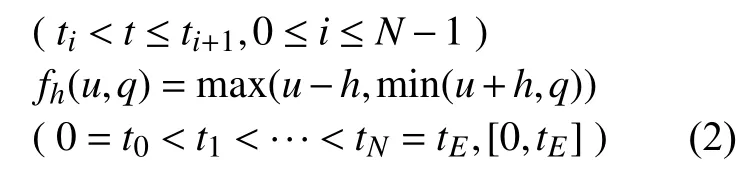

2) P-I Hysteresis Model:Based on Play hysteresis operator,the P-I hysteresis model is represented as following equation.


C. Operator Theory
Operator theory is regarded as a mapping from input space to the output space so that the behavior of the nonlinear system can be captured. Operator theory have advantages that stability analysis can be easily performed. Here, the definition of nonlinear robust right coprime factorization is shown using nonlinear operators and input-output space [20].
1) Operator:The operator is expressed mapping from input to output. This makes it possible to represent the behavior of nonlinear system. Given the operators in this paper both have causality and well-posed property.meansas output correspondence toby mapping


2) Robust Right Coprime Factorization:The feedback control system is shown in Fig. 3.andare extended Banach spaces. The given plant operatorcan be factorized into two stable operatorsandsuch thatis invertible andcan be satisfied. Such a factorization ofis denoted byand the spaceis called a quasi-state space ofIf there also exist two stable operatorsandand the Bezout equation

is satisfied. The control system can be proved to be stable,is an unimodular operator. Moreover, adding the uncertaintyBezout equation expressed by

can be satisfied and Lipschitz equation as below is also maintained.
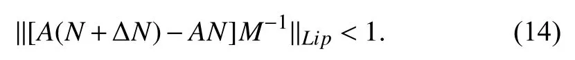
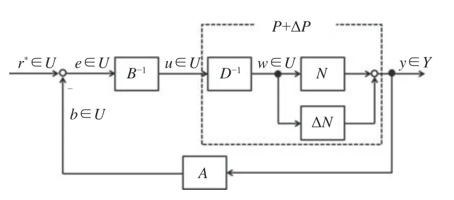
Fig. 3. Nonlinear feedback control system with uncertainties.
The control system is known to be robust stability. Wheredenotes an unimodular operator.
Definition 1:Letbe the set of stable operators fromtoThencontains a subset defined bywhereis invertible withElements ofare called unimodular operators.
Definition 2:Letandbe two extended linear spaces,which are associated respectively with two given Banach spacesandof measurable functions defined on the time domainwhere a Banach space is a complete vector space with a norm. Letbe a subset ofA nonlinear operatoris called a generalized Lipschitz operator onif there exists a constantsuch that for alland for all

Note that the least such constantis given by

which is a semi-norm for general nonlinear operators and is the actual norm for linear[20].
D. Problems Statement
The experimental devices of this study, hysteresis model of the piezoelectric actuators, and operator theory are discussed in this section. According to the obtained models, operator based nonlinear free vibration control design scheme will be explained in next section. Furthermore, the effectiveness of the proposed nonlinear control system will be proved by simulation and experiment later.
III. The Proposed Design Scheme
In this section, according to the obtained models, the robust nonlinear free vibration control design scheme is proposed.First, in order to guarantee the stability of the nonlinear system with unknown input nonlinearity, operator based nonlinear control system is designed. After that, for ensuring the desired tracking performance and reducing the effect of unknown input nonlinearity, operator based tracking compensator and estimation structure are designed,respectively. The designed nonlinear control system is shown in Fig. 4 . In Fig. 4,andare the target value, the error between the target value and output, the feedback signal of the output, the output of the controllerthe input of the controllerthe output of the controllerthe output of the controllerthe output of the controllerthe signal of unknown input nonlinearity compensation, the input of the controllerthe output of the controllerthe control input of the piezoelectric actuator, the output of the P-I hysteresis model, the quasi-state signal of the plant and the signal of the output, respectively.And, the target of this control is stabilizing the vibration at the flexible plate. Therefore, the target value ofis considered in this study.
A. Controllers Design for Stability
Operator based controllers are designed in this section. In this study, we consider the nominal vibration mode with a first-order mode and the uncertainties with the second- and third-order modes. Therefore, the plant with uncertainties is considered the following equation.


Fig. 4. Proposed control system.


B. Compensation for Tracking and Unknown Input Nonlinearity
Considering Fig. 4, the outputcan be expressed by


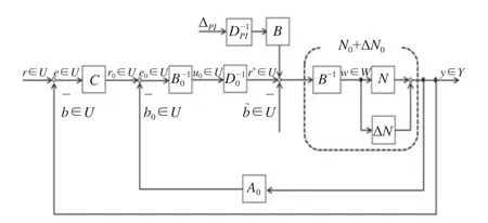
Fig. 5. Equivalent system of Fig. 4.

and the designed operatorCis shown in (32).
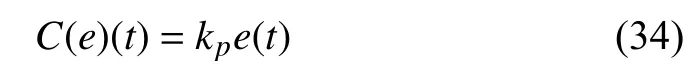

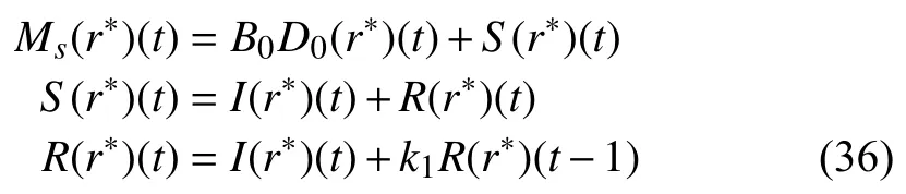
wherek1is a designed parameter.
Thus, for ensuring the desired tracking performance and reducing the effect of unknown input nonlinearity, the following conditions are considered in this study.
1) From (35), the unknown input nonlinearity termcan be obtained by the operator based estimation structure. Therefore, when the condition ofcan be satisfied by the designedthe effect ofcan be made arbitrarily small.
2) From (31), when the condition ofcan be satisfied by the designed operatorsandthe tracking performance can be ensured.
IV. Simulation
In this section, the effectiveness of the proposed design scheme will be discussed by simulation. The simulation results show the free vibration control performance of the flexible plate.
A. Parameter Setting
Parameters of the piezoelectric actuator and the designed controllers are shown in Tables I and II, respectively. In this simulation, only used first-order mode of the flexible plate as the nominal plant. The second- and third-order modes of this simulation are treated as uncertainties. The density functionwhereis used in this simulation.
B. Simulation Results
The simulation in MATLAB is performed. In this simulation, the flexible plate is added the momentMd(t)=0.1sin(f·t)at the bottom of it to make a vibration whent<5s. Wherefis the eigenfrequency of the flexible plate andf=32.74/2π . Ift≥ 5s, we start to control the vibration of the flexible plate with free vibration.

TABLE I Parameters of the Piezoelectric Actuator

TABLE II Parameters of the Controllers
In Fig. 6 , output of the flexible plate with and without control are shown. In with control case, it does not consider the tracking and unknown input nonlinearity compensation.The blue line in Fig. 6 shows the output of the with control,the green line in Fig. 6 shows the output of the without control. Corresponding control input in Fig. 6 is shown in Fig.7. Next in Fig. 8, output of the flexible plate with (blue line)operatorsonly and with (green line) considering tracking compensation are shown. The unknown input nonlinearity compensation was not considered in Fig. 8. Corresponding control input in Fig. 8 is shown in Fig. 9. From the above results, stability and effectiveness of tracking compensation are confirmed by Figs. 6–9 . Furthermore, output of the flexible plate with (blue line) and without (green line)unknown input nonlinearity compensation are shown in Fig. 10. The corresponding control input in Fig. 10 is shown in Fig. 11 . In Fig. 10 , we can be observed that the displacement of the flexible plate with the unknown input nonlinearity compensation reduce more than the result with tracking compensation only. Thus, effectiveness of the designed nonlinear control system is confirmed.

Fig. 6. Output of the system with (blue line) and without (green line) control.
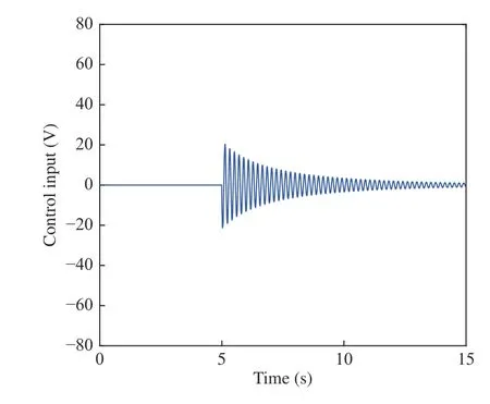
Fig. 7. Corresponding control input in Fig. 6.

Fig. 8. Output of the system with (green line) operators only and with (blue line) considering tracking compensation (without unknown input nonlinearity compensation).

Fig. 9. Corresponding control input in Fig. 8.

Fig. 10. Output of the system with (blue line) and without (green line) unknown input nonlinearity compensation.

Fig. 11. Corresponding control inputs in Fig. 10.
V. Experiment
In this section, the proposed design scheme is confirmed by experiment. The used parameters of the designed controllers are shown in Table III. The frequency of the vibration is 10 Hz, and the vibration of the flexible plate is generated by the servo-motor. Ifcontrollers are started to control the free vibration of the flexible plate. In this experiment, the sampling time is 0.001 s and the experiment time is 15 s. The position of the piezoelectric sensor is the opposite side of the actuator. The actuator is stuck on the desired position by a finite element method (FEM). These positions obtain the strongest moment at the flexible plate. Although displacement of all points on the flexible plate may not become zero, weconsider that all of moments generated on the flexible plate become zero in this research, if the value of the sensor becomes zero.

TABLE III Parameters of the Controllers
Outputs of the flexible plate with (blue line) tracking compensation and without (green line) control are shown in Fig. 12. The corresponding control input in Fig. 12 is shown in Fig. 13 . In Fig. 12 , compared with (blue line) tracking compensation and without (green line) control, the output with considering tracking compensation is stabilized faster than without control case. The stability and effectiveness of considering tracking compensation are confirmed by Figs. 12 and 13 . Finally, outputs with (red line) unknown input nonlinearity compensation and without (green line) control are shown in Fig. 14. The corresponding control input in Fig. 14 is shown in Fig. 15. By the obtained experimental results, the vibration of the flexible plate is stabilized quickly using the unknown input nonlinearity compensation. Thus, the effectiveness of proposed control design scheme is confirmed.

Fig. 12. Outputs of the system with (blue line) tracking compensation and without (green line) control.

Fig. 13. Corresponding control input in Fig. 12.
VI. Conclusion
In this paper, a new robust nonlinear free vibration control design scheme based on operator theory is proposed to realize the desired vibration control performance. Based on the proposed method, the robust stability of the nonlinear system can be guaranteed. And, the operator based tracking compensator and estimation structure are designed to ensure the desired tracking performance and to reduce the effect of unknown input nonlinearity. In future works, the robustness of designed nonlinear control system and hysteresis nonlinearity of the piezoelectric sensor will be discussed.
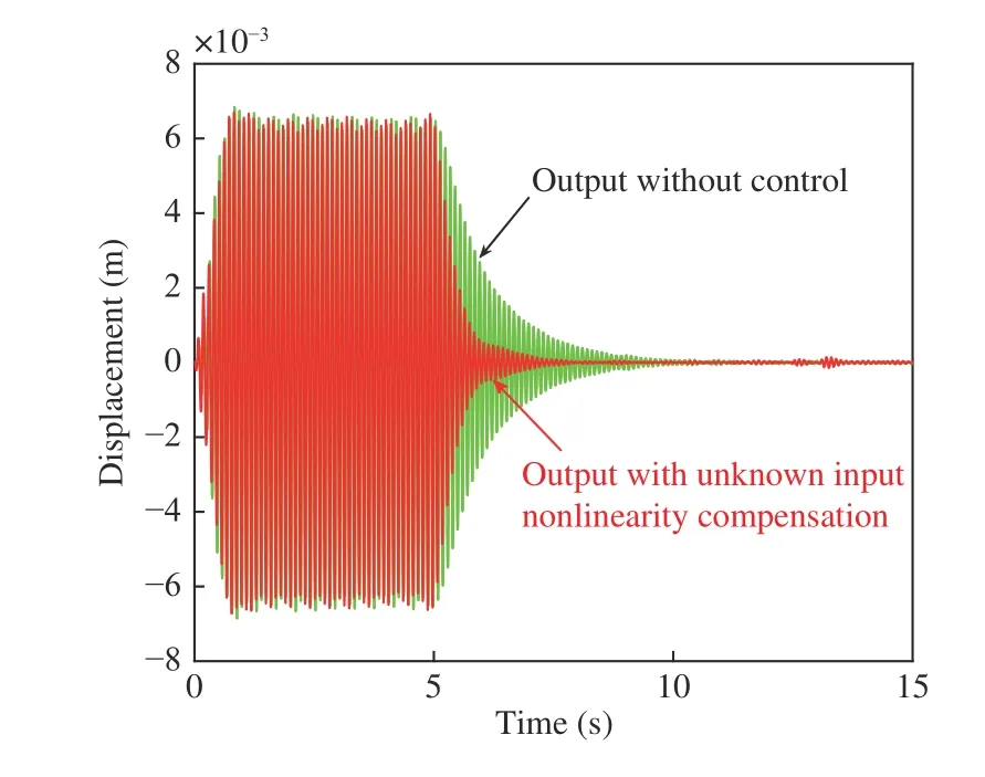
Fig. 14. Outputs of the system with (red line) unknown input nonlinearity compensation and without (green line) control.

Fig. 15. Corresponding control input in Fig. 14.
Appendix A Modeling of Flexible Plate
The controlled object is shown in Fig. 16. In Fig. 16,denotes piezoelectric actuators, andrepresent length of ϵ,directions, respectively. Wheredenote the distance from flexible plate to the center of the servomotor, andis an angle between the η -axis and ϵ-axis. Then the flexible plate is vibrated by the reciprocating movementof the servomotor. The activated piezoelectric actuators will induce moments in the flexible plate, and these moments can be described as following equation:

Fig. 16. Controlled object.
The equation of motion for the flexible plate that is considered piezoelectric actuators is represented as the following equation:

where parameters of the flexible plate are shown in Table IV.

TABLE IV Parameters of the Flexible Plate


Then we obtain
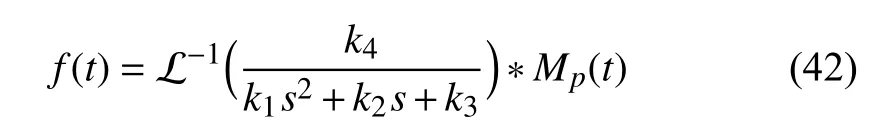
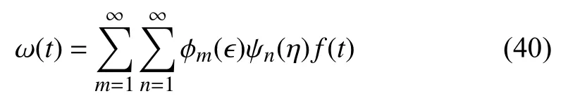
and (40) can be represented as
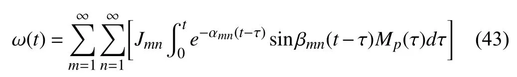
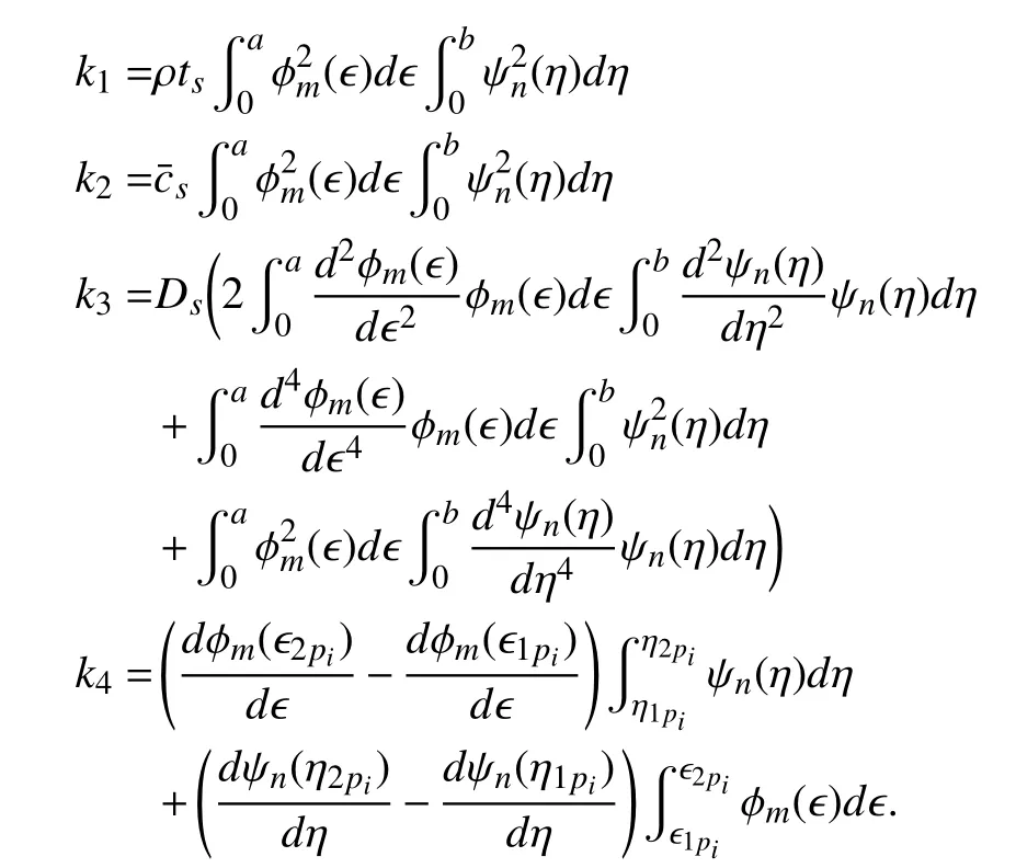
where

Appendix B Positions of Piezoelectric Actuators
In order to select the optimal position, finite element method(FEM) is used in this study. FEM is one of the numerical analysis method to obtain an approximate solution for esoteric differential equation numerically. Dividing the object which have a complicated shape in simple parts firstly, then all the equations established can be solved by combining the governing equation which approximates in their small portion.As a result, the overall behaviour of the system can be predicted. In this study, a coupled analysis tool ANSYS is used in FEM. ANSYS is a software that can be used to parse physical phenomena such as structure, vibration, electric heating, electromagnetic field, piezoelectric-acoustic and thermal fluid, dropping collision, even the coupled problems of a combination of them. Stress distribution and temperature distribution can be performed for a variety of purposes due to the flexibility of the base line. Control effect by the piezoelectric actuator is evaluated in the following:
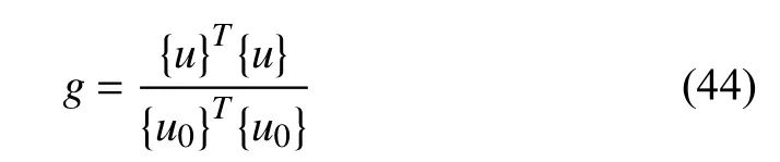
grepresents the ratio of front and rear control norm. Voltage also is taken into consideration, then the evaluation formulacan be expressed as
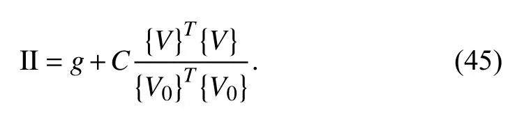
The second term on the right side of (45) is the ratio of reference voltageand actual voltageapplied to each actuator.have two parameters to be given for the control effect and actual voltage. Ifis big enough, voltage effect can be only in a smaller setting of, however, control effect will be more precisely. Control effect can be realized by largest settingwhenConsidering the smallest position obtained by (45), the optimal displacement of actuators can be determined by calculation in the analysis tool ANSYS [16].
 IEEE/CAA Journal of Automatica Sinica2020年2期
- IEEE/CAA Journal of Automatica Sinica的其它文章
- Artificial Intelligence Applications in the Development of Autonomous Vehicles: A Survey
- Data-Driven Based Fault Prognosis for Industrial Systems: A Concise Overview
- Review of Antiswing Control of Shipboard Cranes
- Research Progress of Parallel Control and Management
- Influence of Data Clouds Fusion From 3D Real-Time Vision System on Robotic Group Dead Reckoning in Unknown Terrain
- Effect of a Traffic Speed Based Cruise Control on an Electric Vehicle’s Performance and an Energy Consumption Model of an Electric Vehicle