环路剪切干涉术测量附面层密度场
2020-04-23 03:18蒲泓宇李大海
光电工程 2020年4期
蒲泓宇,李大海,罗 鹏,章 辰
环路剪切干涉术测量附面层密度场
蒲泓宇1,2,李大海1*,罗 鹏1,章 辰1
1四川大学电子信息学院,四川 成都 610065;2中国空气动力研究与发展中心高速所,四川 绵阳 621000
在附面层测量中,需对微小尺度的高速气流变化场进行瞬态测量。数字化的干涉测量方法能定量地解算出流场的密度场,是一种重要的应用。介绍了一种共路干涉的环路剪切干涉方法,对震动不敏感,无需参考面,适合附面层测量使用。采用基于空间位相调制的快速算法,配以脉冲激光器和同步控制系统,可实时地对扰流密度场进行定量测量。该系统采集分辨率200 pixels × 200 pixels,采集频率可达每秒1000帧以上。系统的波前重构方法经过计算机仿真,检测结果优于1/20。在0.6 m风洞对圆柱体尾部附面层进行测量试验,结果表明,在一定风速下,该系统能抑制振动干扰,显著地区分出圆柱体尾部扰流信号和振动噪声,具有良好的应用前景。
径向剪切干涉;密度场;流场;动态测量
1 引 言
“附面层”指紧贴飞行器表面的粘性力不可忽略的流动薄层[1],其厚度在风洞试验中仅为模型表面几个毫米,附面层湍流因为其对飞行器的直接影响受到了广泛关注。其呈现典型的微小尺度随机扰动特点,尺寸小,变化快,由于其理论模型尚不成熟,所以它的实验研究也就越发显得重要[2]。
当前的附面层流动显示方法有粒子示踪法、油流显示法、光学测量方法等,但他们都有各自的缺点。粒子示踪法为在空气中加入烟雾发生器,通过观测烟雾粒子在流场中的密度情况显示流动轨迹。这将会改变气体构成,烟雾粒子体积远大于气体分子,其流场是否与原流场一致在气动力学上存疑。油流显示技术则是附面层流动空气对壁面摩擦应力的反应,只能间接地从一个方面了解其状态。光学测量方法无接触,能直接反应密度差沿光路的积分,但其中的纹影、阴影法都只能显示,不能对密度场定量计算。
干涉测量基于相位差可无接触地定量解算出流场密度场。但传统的干涉测量方法基于时间位相调制,不能检测一个瞬态的变化场[3],且由于高速气流产生的振动影响,干涉图像易被干扰,解算困难,在附面层测量中不能适用[4]。
环路径向剪切干涉仪(Cyclic radial shearing interferometer,CRSI)作为一种高精密干涉计量技术不需要专门设置参考光路[5],采用共光路结构,路径相同,振动对其影响一致[6],因此其具有对振动不敏感的特点,适合在附面层测量中使用。利用基于空间位相调制的方法改进其结构,配合脉冲激光器和同步控制系统,对附面层密度场实现瞬态高精度的检测。分析其在高风速振动环境下的数据有效性,在一定马赫数以下的环境中显著区分出扰流信号和随机噪声,具有良好的应用前景。
2 国内外概况
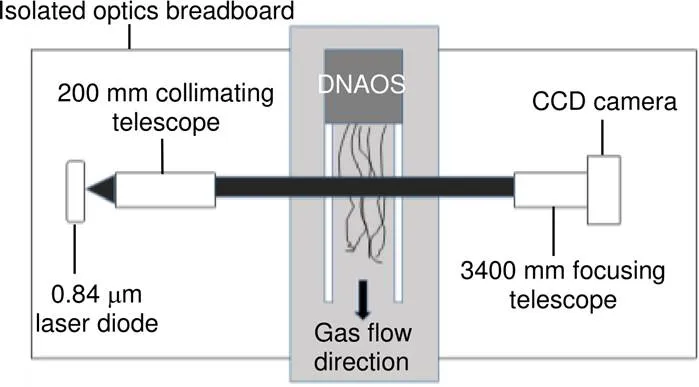
早在上世纪90年代,美军在阿拉巴马州即利用剪切干涉系统对超声速尾流剪切层进行了成像试验。如图1所示[7],但当时只是作为图像参考,并不能区分瞬态细节。2001年,Griffin等人提出空间移相剪切干涉仪,可以实现瞬态测量[8]。2018年,罗切斯特大学Guo等人利用径向剪切干涉仪实现了对时间极短的飞秒脉冲瞬态测量[9]。
在国内,浙江大学杨甬英教授及其课题组在2008年就提出利用空间位相调制的剪切干涉系统实现对高速流场的测量,并验证了其虽然采用共路干涉,但在静态环境下,与非共路干涉的ZYGO干涉仪精度差仅0.0043[10]。2016年,其课题组又进一步利用偏折型径向剪切干涉仪在实验室条件下实现了在部分遮挡下的瞬态实时测量[11]。2017年,中国科学院Gu等[12]设计了一种基于偏振相移原理的空间位相调制剪切干涉系统,抗干扰能力强,对振动有显著的抑制作用。
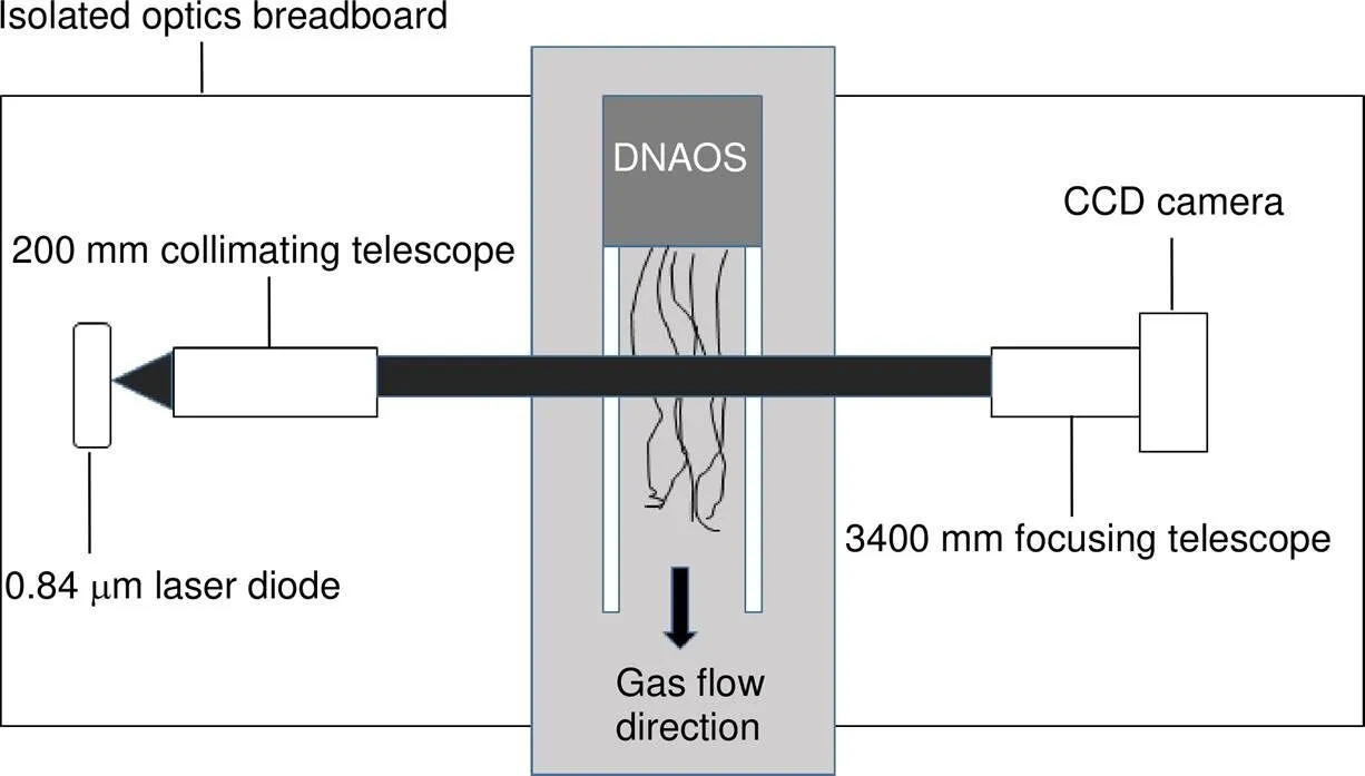
图1 剪切层气动光学效应测量原理图
3 测量原理
3.1 环路径向剪切干涉系统
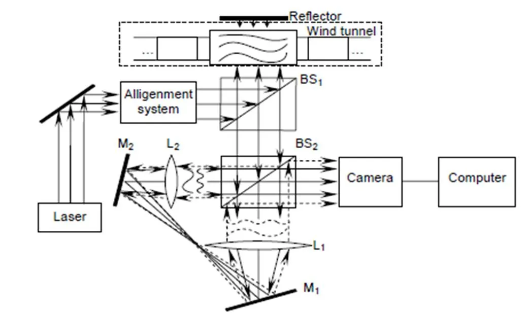
环路径向剪切干涉系统最早是由Murty于1964年提出,在此次风洞环境中,其在附面层测量中的工作原理如图2所示。

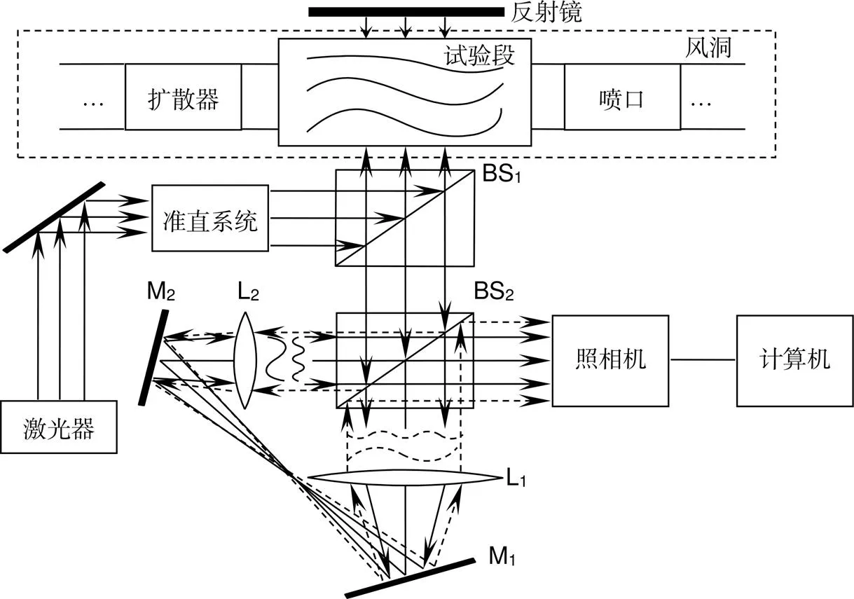
图2 环路径向剪切干涉测量风洞流场原理
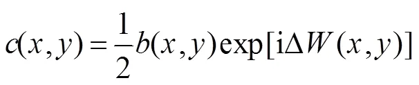
3.2 基于空间位相调制的密度场重建算法


其中:
对式(2)进行傅里叶变换,得到干涉条纹图的频谱分布可表示为

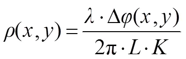
其中:是光源波长,是Gladstone-Dale系数,是光束穿过气流的路程。
4 系统设计
4.1 光学系统设计指标
为风速与音速的比值,即马赫数。若很小,则密度变化可以忽略,属不可压缩流动范畴,密度场测量意义不大;若较大,则密度变化较大,属可压缩流动。一般取=0.4为其边界,另因超音速流动振动较大,本次试验针对马赫数0.4~1.0亚音速进行设计。附面层尺寸普遍在10 mm以下,基于冗余设计,本次设计光斑尺寸20 mm。
1) 动态范围、测量精度
其附面层湍流强度为波动减少的速度与自由流速度的比值,有经验公式[21]:
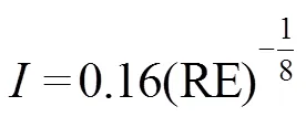
其中RE为雷诺数,随风速增大而增大,与湍流强度成反比,大多数湍流强度在该值以下,=0.4时该型风洞雷诺数最小为1.5´106,代入式(7),取得湍流强度为2.7%。流场密度与速度的关系满足克拉伯龙方程:
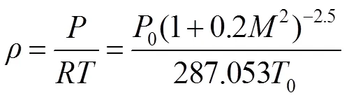
将各参数代入式(8)计算,湍流密度相对当前密度的波动为1.85´10-3kg/m3,代入式(6)得到光程差的动态范围为1575 nm。本装置光源波长为560 nm,湍流平均波动相位在2.8,即仪器测量动态范围需大于2.8,测量精度应小于其动态范围一个以上数量级,才认为有区分度,因此需在0.1以下。
2) 采样时间、分辨率
在现有粒子示踪法测量设备中,中国空气动力研究中心PIV技术采样时间在1 ms,分辨率64×64;国防科大NPLS技术,其采样时间1 ms,分辨率200×200。参照其设定,本设备设计采样时间1 ms,分辨率200×200。
4.2 同步采集系统设计
如图3所示,该采集系统以基于开普勒望远系统的环路径向剪切干涉仪为核心,包括了脉冲激光光源、环路剪切干涉系统部分、相机及数据处理系统。光束直径为20 mm,采样分辨率200×200。
同步控制器接收到中断信号时,就输出两路方波时序信号。一路输入脉冲激光器电源以触发脉冲激光,一路输入采集卡,触发相机的快门打开,从而使得激光器产生的脉冲激光与相机快门打开时间准确同步。
脉冲激光通过同步控制器配合相机进行拍摄,由于曝光时间短,可以摒除扰流在时间上积分的干扰,得到瞬态的图像数据。
4.3 数据处理系统设计及其仿真结果
软件处理流程如图4所示。
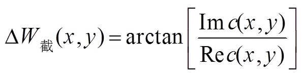
原始干涉条纹由缩小波前与扩大波前的相位差产生,经过傅里叶变换至频域,通过带通滤波器对正一级或负一级频谱进行数字加权滤波,将其附近的频谱信息提取出来,并将频谱移中以去掉载频0,进行傅里叶逆变换,利用式(5)提取得到截断相位,再经相位展开获得相位差波前的连续相位。
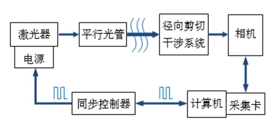
图3 同步采集系统控制图
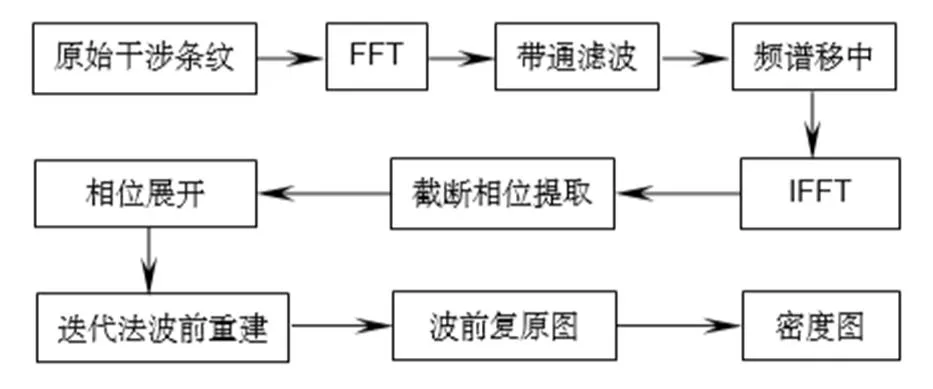
图4 数据处理流程图
为方便光路布置,本系统设计的径向剪切比为0.67,并不足够小,因此重叠区域的扩大光束不能简单地近似于平面波处理,此相位差波前还需要通过迭代法缩小径向剪切比以提高波前重建精度。迭代的约束条件为当前次求和结果与前+1次求和结果之间的差小于/1000,此时可认为扩大波前近似平面[12],其仿真结果如图5、图6所示。
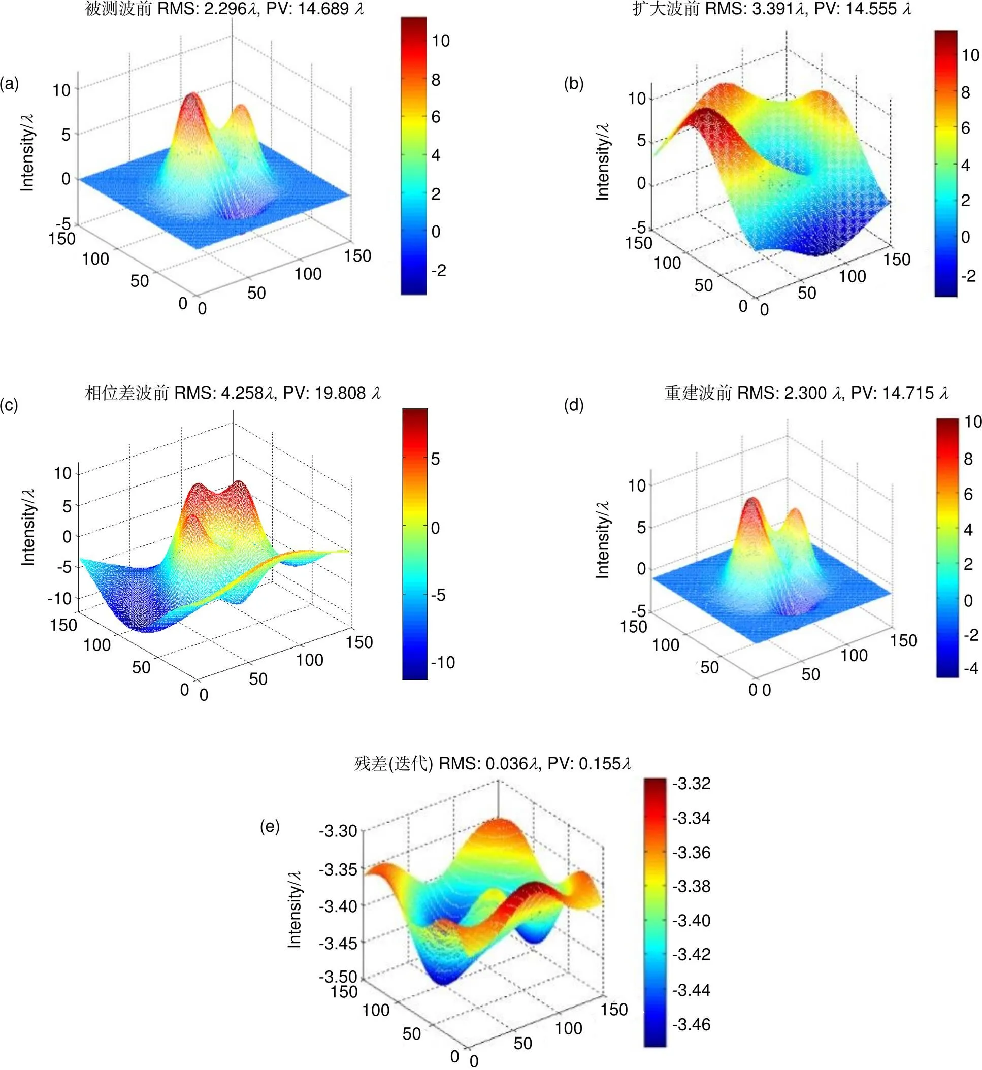
图5 第一类波前仿真。(a) 原始波前;(b) 扩大波前;(c) 相位差波前;(d) 重建波前;(e) 残差
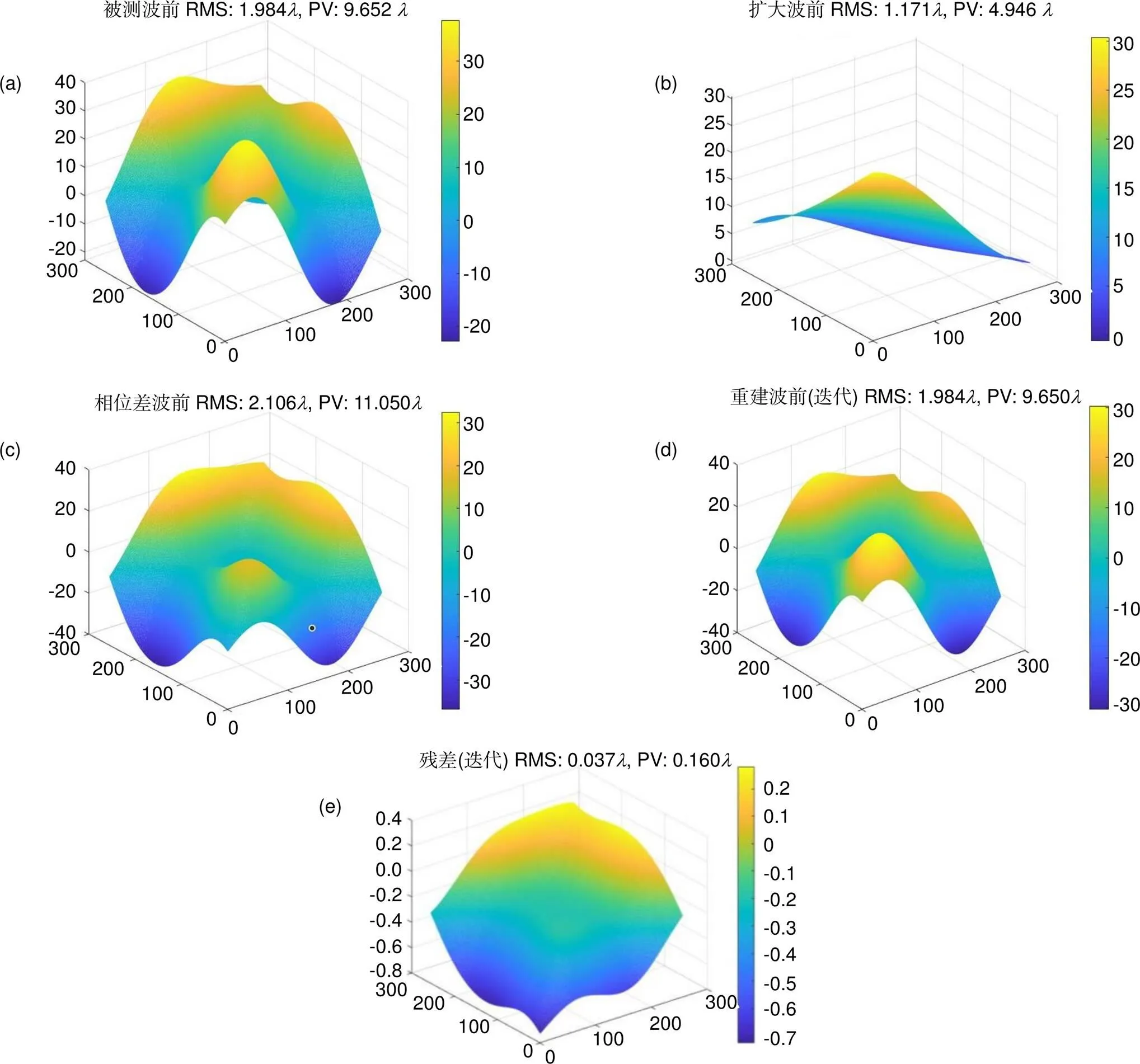
图6 第二类波前仿真。(a) 原始波前;(b) 扩大波前;(c) 相位差波前;(d) 重建波前;(e) 残差
5 实验及数据分析
系统在中国空气动力研究与发展中心0.6 m风洞进行了附面层测量的实验,该风洞是当前国内流场品质最好的亚跨超声速风洞之一,流场均匀性良好,可认为在无模型条件下,风洞流场密度值近似均匀。
在同一马赫数下,分别对空风洞和倾斜圆柱体侧后方附面层进行测量。光斑与圆柱体的相对位置如图7所示,测量区域边缘处距圆柱体1 mm,处于附面层影响范围内。
图8与图9分别展示了在马赫数0.4的条件下,在同一测量位置加装模型和不加装模型时10 s内连续测得的相对密度分布图,加装模型时测得的为附面层湍流,不加装模型时测得的是风洞自由流。可以直观地看到,有模型时测得图像中湍流黄色扰动较多,未加装模型时相位分布较为平滑,其波动为风洞振动给系统带来的扰动。附面层湍流叠加于该扰动之上,位置与尺度可分辨。
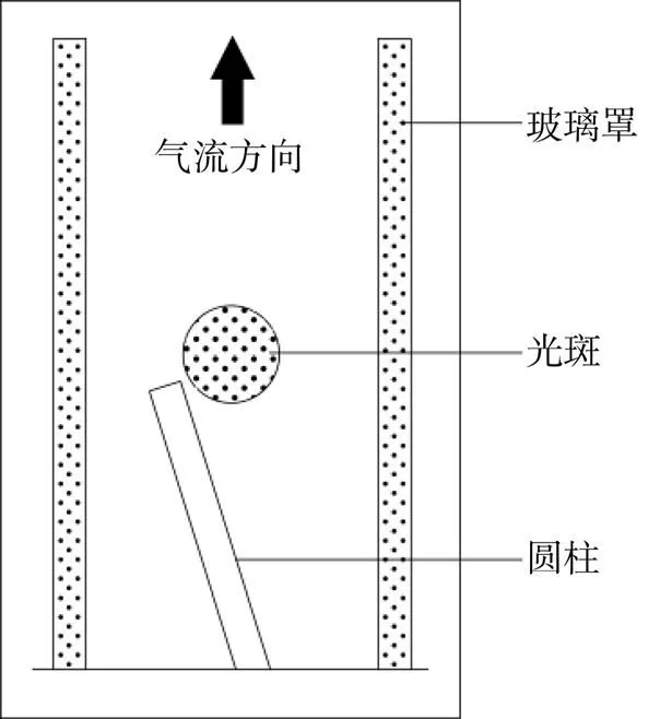
图7 测量区域
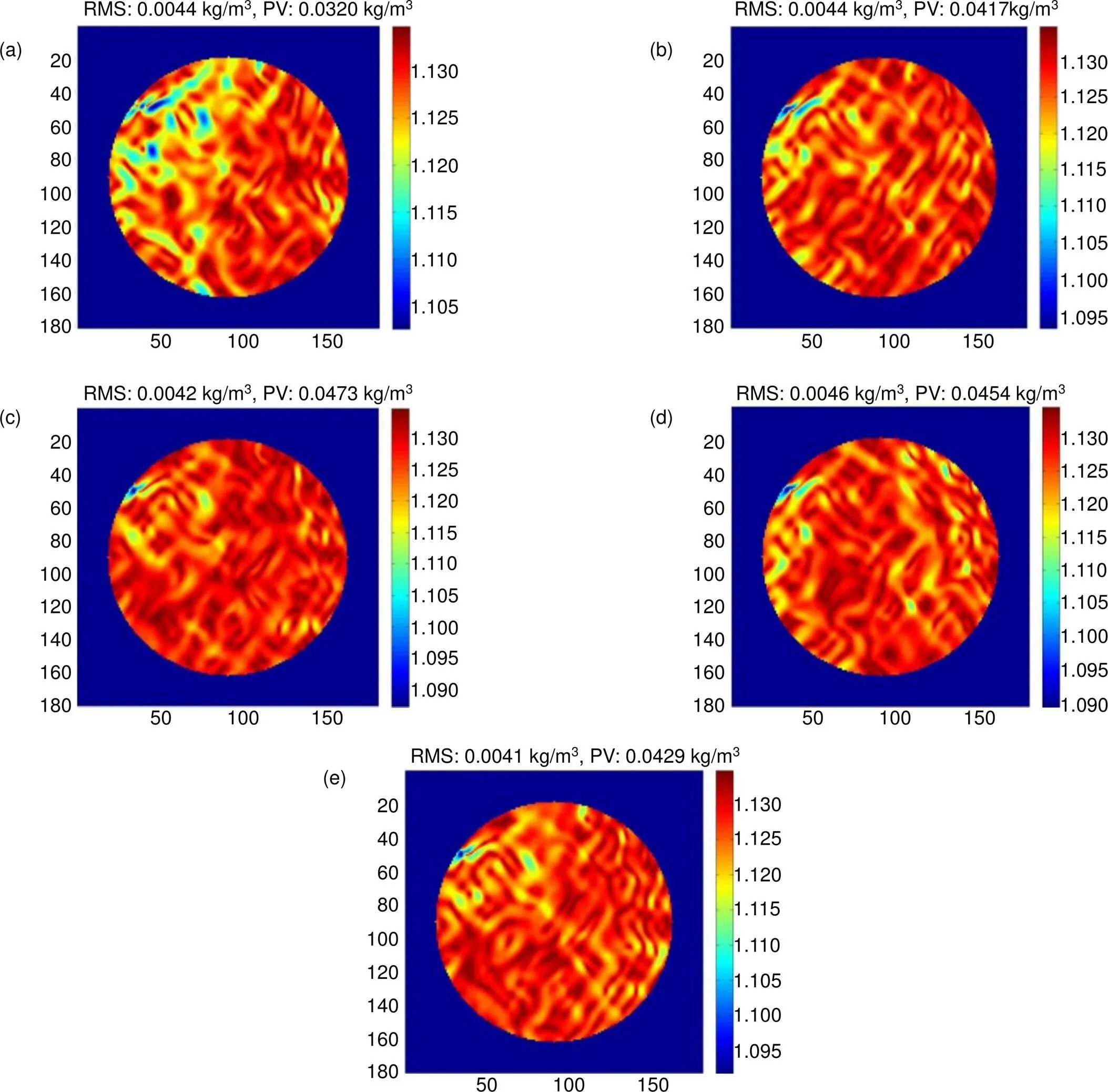
图8 有模型扰流时密度图(单位:kg/m3)。(a) 1.2 s;(b) 3.6 s;(c) 4.5 s;(d) 6.3 s;(e) 7.8 s
在同一马赫数时,比较在圆柱扰流状态下和空风洞状态下多幅图像相位分布图的RMS值,以其作为信噪比,如表1所示。
可见,随着马赫数增大,振动逐渐增大,系统抗振能力相应衰减,在低马赫数时扰流信号强度显著高于振动带来的背景噪声。
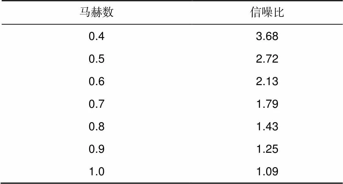
表1 多幅图像相位RMS比值对比
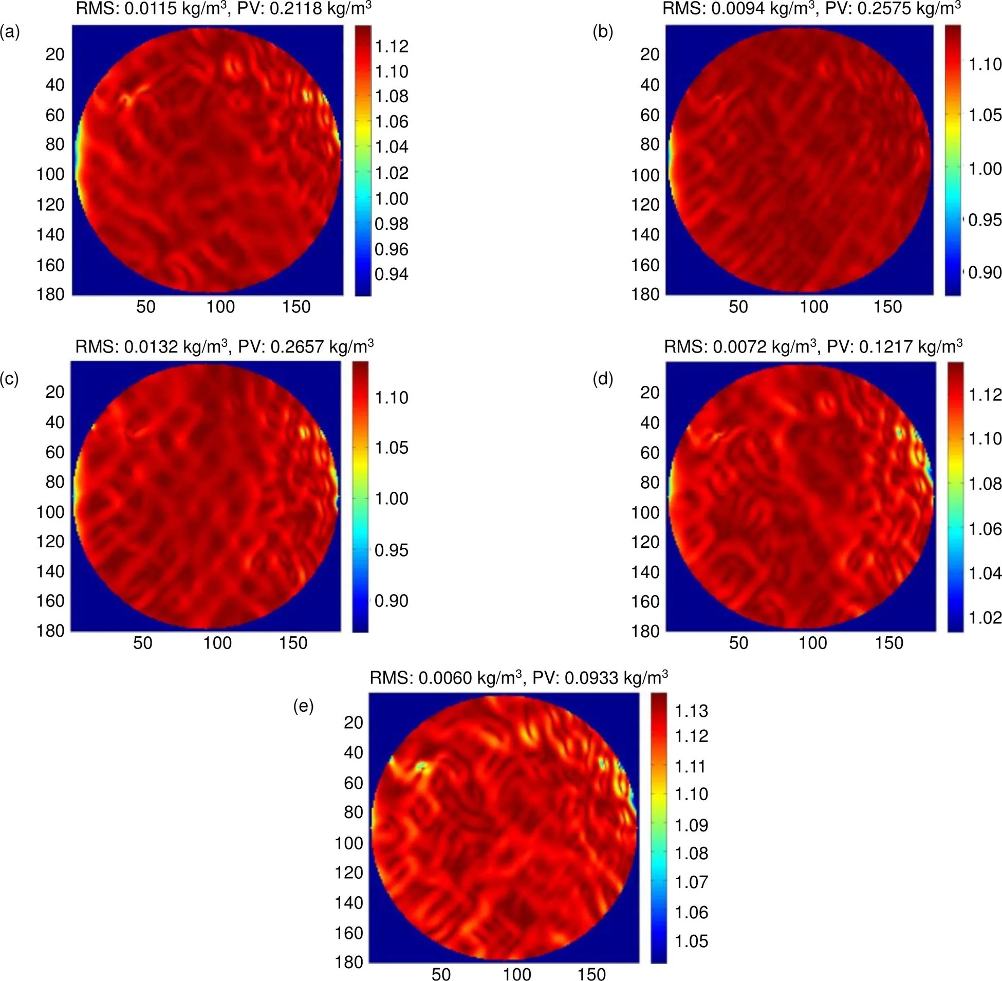
图9 空风洞时密度图(单位:kg/m3). (a) 1.3 s;(b) 3.4 s;(c) 4.7 s;(d) 6.9 s;(e) 7.7 s
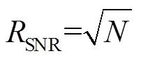
该噪声变化点在采样时间内随机分布,即为满足泊松分布的散斑噪声,信噪比(SNR)为

6 结 论
环路径向剪切干涉组合采用共光路结构,易于在附面层测量环境下布局使用,利用基于空间位相调制的快速算法,可以对附面层流场进行动态实时检测。该系统波前检测精度高,抗噪抗干扰性能良好。试验表明,0.7马赫数以下,可抑制气流振动干扰,显著区分出扰流与背景,在附面层测量这种实时性要求比较高的场合有广泛的应用前景。
此次实验为验证性实验,为方便光路调试,所有光学部件采用可调节式,如若能将其集成与固定化,并单设直接来自地基的支撑架,应能更好地抑制震动。
[1] Yu J Y. Flow control with the vortex induced by DBD plasma in boundary layer flow[D]. Harbin: Harbin University of Technology, 2017. 俞建阳. DBD等离子体诱导涡结构控制附面层流动研究[D]. 哈尔滨: 哈尔滨工业大学, 2017.
[2] Li Q, Jiang T, Chen S Y,. Measurement technique and application of boundary layer transition in shock tunnel[J]., 2019, 40(8): 122740.
李强, 江涛, 陈苏宇, 等. 激波风洞边界层转捩测量技术及应用[J]. 航空学报, 2019, 40(8): 122740.
[3] Lu X F, Zhang T X, Hong H Y. Image correction method with pixel deviation caused by aero-optics effects[J]., 2007, 36(5): 758–761.
卢晓芬, 张天序, 洪汉玉. 气动光学效应像素偏移图像校正方法研究[J]. 红外与激光工程, 2007, 36(5): 758–761.
[4] Yang F R, Chen L, Yan B,. Measurement of turbulence velocity fluctuations in transonic wind tunnel using Interferometric Rayleigh Scattering diagnostic technique[J]., 2018, 32(3): 82–86.
杨富荣, 陈力, 闫博, 等. 干涉瑞利散射测速技术在跨超声速风洞的湍流度测试应用研究[J]. 实验流体力学, 2018, 32(3): 82–86.
[5] Ling T, Liu D, Yang Y Y,. Off-axis cyclic radial shearing interferometer for measurement of centrally blocked transient wavefront[J]., 2013, 38(14): 2493–2495.
[6] Luo J J, Hou S X, Xu J,. Study of measuring laser beam wave-front based on cyclic radial shearing interferometer[C]//. Beijing: Chinese Society of Astronautics, Chinese Society of Aeronautics and Astronautics, China Ordnance Society, Chinese Optical Society, Chinese Institute of Electronics, 2010.
罗积军, 侯素霞, 徐军, 等. 环路径向剪切干涉测量激光束波前畸变的研究[C]//第九届全国光电技术学术交流会论文集. 北京: 中国宇航学会, 中国航空学会, 中国兵工学会, 中国光学学会, 中国电子学会, 2010.
[7] Couch L L, Kalin D A, McNeal T. Experimental investigation of image degradation created by a high-velocity flow field[J]., 1991, 1486: 417–423.
[8] Griffin D W. Phase-shifting shearing interferometer[J]., 2001, 26(3): 140–141.
[9] Lam B, Guo C L. Complete characterization of ultrashort optical pulses with a phase-shifting wedged reversal shearing interferometer[J]., 2018, 7: 30.
[10] Yang Y Y, Liu D, Wang D D,. Real-time interferometry with high speed and precision for transient flow field and its applications[J]., 2008, 37(5): 757–760.
杨甬英, 刘东, 王道档, 等. 动态变化场的高速高精度实时干涉检测[J]. 红外与激光工程, 2008, 37(5): 757–760.
[11] Ling T. Reconstruction of three-dimensional refractive index field based on multi-wave shearing interferometry and optical tomography[D]. Hangzhou: Zhejiang University, 2016.
凌曈. 基于多波前剪切干涉与光学层析技术三维折射率场重构研究[D]. 杭州: 浙江大学, 2016.
[12] Gu L Y, Liu L, Hu S Y,. Polarization phase-shifting lateral shearing interferometer with two polarization beam splitter plates[J]., 2017, 24(4): 600–604.
[13] Medhi B, Hegde G M, Gorthi S S. Improved quantitative visualization of hypervelocity flow through wavefront estimation based on shadow casting of sinusoidal gratings[J]., 2016, 55(22): 6060–6071.
[14] Zhang C. A study of polarization phase shifting radial shearing interferometry and dynamic measurement in flow field[D]. Chengdu: Sichuan University, 2018.
章辰. 偏振相移径向剪切干涉仪及流场动态测量研究[D]. 成都: 四川大学, 2018.
[15] Thornton D E, Spencer M F, Perram G P. Deep-turbulence wavefront sensing using digital holography in the on-axis phase shifting recording geometry with comparisons to the self-referencing interferometer[J]., 2019, 58(5): A179–A189.
[16] Tian C, Chen X F, Liu S C. Modal wavefront reconstruction in radial shearing interferometry with general aperture shapes[J]., 2016, 24(4): 3572–3583.
[17] Zhang C, Li D H, Li M M,. Wavefront reconstruction algorithm based on interpolation coefficients for radial shearing interferometry[J]., 2016, 10155: 1015539.
[18] Wang Z Y, Wang S, Yang P,. Multiple-wave radial shearing interferometer based on a Fresnel zone plate[J]., 2018, 26(26): 34928–34939.
[19] Padghan P P, Alti K M. Quantification of nanoscale deformations using electronic speckle pattern interferometer[J]., 2018, 107: 72–79.
[20] Dai F Z, Zheng Y Z, Bu Y,. Modal wavefront reconstruction based on Zernike polynomials for lateral shearing interferometry[J]., 2017, 56(1): 61–68.
[21] Sessa V, Xie Z T, Herring S. Turbulence and dispersion below and above the interface of the internal and the external boundary layers[J]., 2018, 182: 189–201.
Measurement of flow density field by cyclic radial shearing interferometer
Pu Hongyu1,2, Li Dahai1*, Luo Peng1, Zhang Chen1
1School of Electronics and Information, Sichuan University, Chengdu, Sichuan 610065, China;2High Speed Institute, China Aerodynamics Research and Development Center, Mianyang, Sichuan 621000, China
Principle diagram of cyclic radial shearing interferometry
Overview:"Boundary layer" refers to a thin flow layer with a non-negligible viscous force close to the aircraft surface. Its thickness is only a few millimeters of the model surface in the wind tunnel test. It shows typical characteristics of small scale random disturbance, small size and fast change.
The current methods of boundary layer flow display include particle tracer method, oil flow display method and optical measurement method, but they all have their own shortcomings. Particle tracer method is to add smoke generator into the air and show the flow track by observing the density of smoke particles in the flow field. As the size of the smoke particles is much larger than that of the gas molecules, this method will change the composition of the gas. Oil flow display technology is the reaction of the flowing air in the boundary layer to the friction stress on the wall surface. The optical measurement method has no contact and can directly reflect the integral of density difference along the optical path, but the schlieren and shadow methods can only display and cannot calculate the density field quantitatively.
Based on phase difference, the density field of flow field can be calculated quantitatively. However, the traditional interferometry method based on time phase modulation cannot detect a transient change field the interference image is easily interfered due to the influence of vibration generated by high-speed airflow, which is difficult to solve, so it cannot be applied in the boundary layer measurement.
This paper proposed a measurement system based on loop radial shear interference, with high wavefront detection accuracy, good anti-noise and anti-interference performance, and suitable for use in boundary layer measurement. The system adopts the fast transform method based on spatial phase modulation, which loads the information of shear wave surface onto the carrier, and an image can quickly recover the wavefront by using the fast Fourier transform method, avoiding the influence of dynamic changes of measured wavefront and realizing real-time dynamic detection. For the complex wavefront of the boundary layer, the iterative method is used to improve the wavefront reconstruction accuracy. The simulation results show that the residual root mean square (RMS) value is better than 1/20. This paper introduces the realization of hardware system and software process in detail. The principle of the algorithm is also presented. The experimental results in a 0.6 m wind tunnel show that the system can restrain the vibration interference and distinguish the disturbance signal and the vibration noise remarkably. The proposed method has broad application prospects in real-time boundary layer measuring.
Citation: Pu H Y, Li D H, Luo P,. Measurement of flow density field by cyclic radial shearing interferometer[J]., 2020,47(4): 190390
Measurement of flow density field by cyclic radial shearing interferometer
Pu Hongyu1,2, Li Dahai1*, Luo Peng1, Zhang Chen1
1School of Electronics and Information, Sichuan University, Chengdu, Sichuan 610065, China;2High Speed Institute, China Aerodynamics Research and Development Center, Mianyang, Sichuan 621000, China
Transient measurements of high-speed airflow field are needed in the measurement of boundary layer. Digital interferometry can measure flow field quantitatively to obtain density information, which is very necessary in flow field measurement. In this paper, a common-path shearing interferometry method is introduced. It is insensitive to vibration and does not need a reference plane. It is suitable for flow field measurement. A fast algorithm based on spatial phase modulation, coupled with a pulse laser and a synchronous control system, is used to measure the disturbance density field quantitatively in real time. The acquisition resolution of the system is 200 pixels × 200 pixels, and the acquisition frequency can reach more than 1000 frames per second. The wavefront reconstruction method of the system has been simulated by computer, and the detection result is better than 1/20. The experimental results in a 0.6 m wind tunnel show that the system can restrain the vibration interference and distinguish the disturbance signal and the vibration noise remarkably. It has good application prospects.
radial shear interferometry; density field; flow field; dynamic measurement
National Natural Science Foundation of China (11732016, 11402286)
* E-mail: lidahai@scu.edu.cn
TN247;TB82
A
蒲泓宇,李大海,罗鹏,等. 环路剪切干涉术测量附面层密度场[J]. 光电工程,2020,47(4): 190390
: Pu H Y, Li D H, Luo P,Measurement of flow density field by cyclic radial shearing interferometer[J]., 2020, 47(4): 190390
10.12086/oee.2020.190390
2019-07-08;
2019-11-04基金项目:国家自然科学基金资助项目(11732016,11402286)
蒲泓宇(1986-),男,硕士研究生,工程师,主要从事波前检测方面的研究。E-mail:115395674@qq.com
李大海(1968-),男,教授,博士生导师,主要从事光学信息处理、波前传感、三维立体显示等方面的研究。E-mail:lidahai@scu.edu.cn
版权所有©2020中国科学院光电技术研究所
猜你喜欢
军民两用技术与产品(2021年8期)2021-11-24
数学物理学报(2021年5期)2021-11-19
民用飞机设计与研究(2021年1期)2021-04-06
科学技术与工程(2020年30期)2020-12-04
小哥白尼(野生动物)(2020年3期)2020-07-27
数学大王·中高年级(2018年11期)2018-12-17
燃气涡轮试验与研究(2015年3期)2015-08-16
燃气涡轮试验与研究(2014年3期)2014-02-27
实验流体力学(2013年2期)2013-09-21
燃气涡轮试验与研究(2012年3期)2012-05-07