
Mesoscale fracture behavior of Longmaxi outcrop shale with different bedding angles:Experimental and numerical investigations
2020-04-17 13:48JinpingZuoJingfngLuRojinGhndrizJintoWngYnhongLiXioynZhngJunLiHongtoLi
Jinping Zuo ,Jingfng Lu ,Rojin Ghndriz ,Jinto Wng ,Ynhong Li ,Xioyn Zhng ,Jun Li ,Hongto Li
a School of Mechanics and Civil Engineering,China University of Mining and Technology,Beijing,100083,China
b State Key Laboratory of Coal Resources and Safe Mining,China University of Mining and Technology,Beijing,100083,China
c Department of Mechanical Engineering,University of Massachusetts,Dartmouth,02747,USA
Keywords:Longmaxi shale Three-point bending test Fracture toughness Fracture energy Crack propagation Anisotropic cohesive damage Extended finite element method(XFEM)
A B S T R A C T The mechanical properties and fracturing mechanism of shale containing beddings are critically important in shale gas exploitation and wellbore stability.To investigate the effects of shale bedding on crack behavior and fracturing mechanism,scanning electron microscope(SEM)with a loading system was employed to carry out three-point bending tests on Longmaxi outcrop shale.The crack initiation and propagation of Longmaxi shale were observed and recorded by taking photos during loading.The cracking paths were extracted to calculate the crack length through a MATLAB program.The peak load,fracture toughness and fracture energy all increase with the bedding angle from 0°to 90°.The crack length and energy were also found to increase with the bedding angle in the range of 0°-60°and then drop slightly.The fracturing mechanism of shale includes the main crack affected by the bedding angle and disturbed by randomly distributed particles.The main cracking path was accompanied by several microcrack branches which could form an interconnected crack system.When the main crack encounters larger sedimentary particles,it will deflect around the particles and then restore to the initial direction.A numerical technique using extended finite element method(XFEM)coupled with anisotropic cohesive damage criteria was developed,which is able to capture the dependence of crack propagations on bedding angle and sedimentary particles.This study sheds light on understanding and predicting mesoscale fracture behavior of shale with different bedding angles.
1. Introduction
High-quality,eco-friendly economic development in China puts huge demands on shale gas.The large-scale commercial development for shale gas in China was initiated in 2009.Following the USA and Canada,China has become the third country that has realized the industrial shale gas production(Dong et al.,2016).The shale gas production increased from 25 million m3in 2012 to more than 9 billion m3in 2017,showing a promising prospect of shale gas development in China(Ma et al.,2018).
Hydraulic fracturing is a key technology widely applied in shale gas exploitation and production. A fully developed fracture network caused by hydraulic fracturing provides a guarantee for increasing shale gas production.However,the formation mechanism of fracture network has not been well understood.The failure mechanism of shale is intricate,because the preexisting bedding acting as weak plane exerts complex impacts on mechanical properties of shale.It has been proved that Young’s modulus(Niandou et al.,1997;Ambrose,2014),Poisson’s ratio(Ambrose,2014),fracture toughness(Lee et al.,2015;Chandler et al.,2016;Luo et al.,2018),shear strength(Heng et al.,2015),compressive strength(Kovrizhnykh et al.,2017)and permeability(Yu et al.,2013)vary with the bedding angle,indicating that crack behaviors are strongly influenced by bedding plane.Evolution of fracture network has been investigated experimentally(Guo et al.,2014;Zhang et al.,2017a)and numerically(Kim and Moridis,2015;Zhang et al.,2017b).The bedding plane may be dominant in fracturing when shale is under certain stress conditions.For example,experimental results obtained by Guo et al.(2014)indicated that when the horizontal in situ stress difference is less than 9 MPa,hydraulic fracture can easily propagate along with the natural fractures,forming a fracture network.
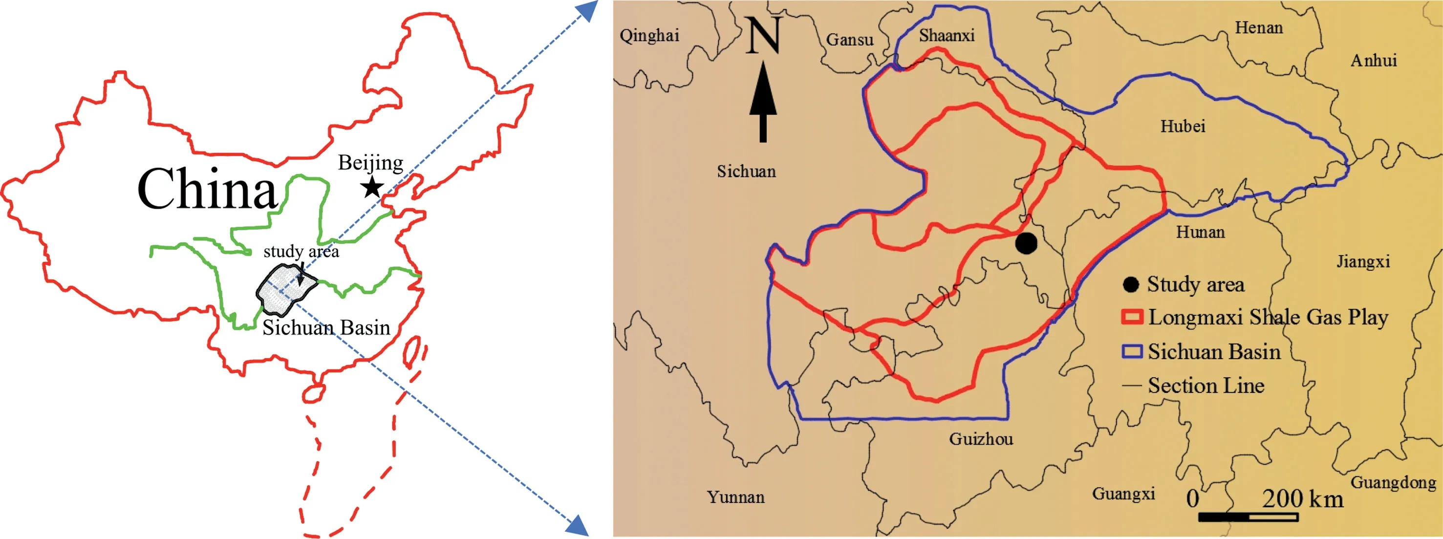
Fig.1.Distribution of lower Silurian Longmaxi shale gas layer in Sichuan Basin,China.
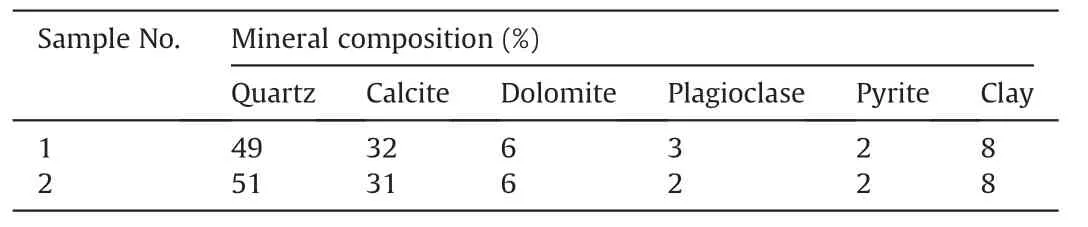
Table 1 X-ray diffraction results of Longmaxi shale.
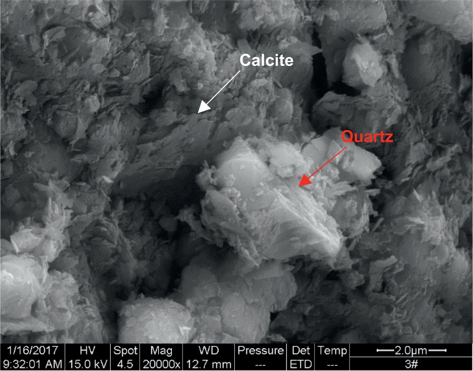
Fig.2.Microstructure and mineral composition of Longmaxi shale by SEM energy spectrum analysis.
To investigate the effects of bedding on crack propagation,a number of laboratory tests have been conducted, considering different bedding angles.By performing semicircular bend tests on Marcellus shale containing calcite-filled veins,Lee et al.(2015)found that as the approaching angle became more oblique to the induced fracture plane,the induced fractures were more likely to divert into the vein.Chandler et al.(2016)conducted the modified short rod tests on Mancos shale and found a tendency for deviation toward the bedding-parallel orientation for cracks propagating nonparallel to bedding.In situ observations on crack behaviors are expected to reveal the failure mechanism of rock,which shows both the local and global deformation.Morgan(2017)used digital image correlation(DIC)method to determine crack behaviors and found a significant influence of bedding plane on the cracking pattern of Opalinus shale.Taking in situ observation technique based on scanning electron microscope (SEM), the fracturing mechanism of marble(Zuo et al.,2015),basalt(Zuo et al.,2014a),siltstone(Zuo et al.,2014b),granite(Zuo et al.,2017)and sandstone(Zuo et al.,2010,2016)was investigated.So far,researches on the cracking process of shale at meso-scale are rather limited.Cui and Han(2018)observed the crack growth of Longmaxi shale using SEM and discussed the fracturing mechanism.However,they did not take the bedding angle into consideration.

Fig.3.(a)Longmaxi shale block with dimensions of 300 mm×300 mm×300 mm,and(b)Sampling angle.

Table 2 Physico-mechanical properties of Longmaxi shale.

Fig.4.Sizes of three-point bending specimen(unit:mm).
In this paper,three-point bending tests have been carried out on the Longmaxi outcrop shale,considering different angles between bedding plane and loading direction.The process of crack initiation and propagation was observed using SEM with a loading system.Mechanical properties,such as peak load,fracture toughness and fracture energy,were analyzed,with respect to the bedding angle.To model the cracking process of Longmaxi shale within different bedding angles, the extended finite element method (XFEM)coupled with an anisotropic cohesive zone model(CZM)was utilized in this study,which agreed well with the experimental observations. Besides, the effects of particle inclusion on crack behaviors were discussed through simulations of a single edge notch tension model.
2. Experimental methods
2.1. Sample preparation
Longmaxi shale gas field in Sichuan Basin,China has been successfully explored in recent years.The Longmaxi outcrop shale specimens used in this research are sampled from Pengshui County in Chongqing,China(Fig.1).Results of X-ray diffraction in Table 1 and SEM energy spectrum analysis in Fig.2 indicate that the main mineral constituents of Longmaxi shale are quartz and calcite cemented by clay contents,which account for about 50% and 30% ,respectively.The main component of clay is illite.
The outcrop shale block is ash black in color and its sizes are about 300 mm×300 mm×300 mm,as shown in Fig.3a.Physicomechanical properties, including density, uniaxial compressive strength(UCS),elastic modulus(E)and Poisson’s ratio(λ),were tested as per the International Society for Rock Mechanics(ISRM)suggested methods(Ulusay,2015)and are listed in Table 2.The specimen was prepared by cutting a 5-mm thick slice from a large shale block. A cuboid-shaped specimen was made into 25 mm×10 mm×5 mm(length×width×thickness)and the sizes of specimens are list in Table 2.Taking different directions of bedding plane into consideration,the angles between the long edge of the specimen and the bedding plane were set as 0°,30°,45°,60°and 90°,as shown in Fig.3b.A notch was set at the middle of the long edge of the specimen,which was about 4 mm long and 0.4 mm wide.We define θ as the angle between loading direction and bedding plane,as shown in Fig.4.The specimen was named as A°-B.For example,30°-1 denotes specimen group No.1 with θ=30°.

Fig.5.SEM with a loading system.

Fig.6.Typical cracking process of specimen 30°-3 and the corresponding load-displacement curve.
2.2. Experimental procedures
The experiments were conducted using SEM with a loading system,as shown in Fig.5.Loading tests were performed in the chamber of SEM,which made it possible to observe and record the cracking process during loading.To fix the specimen and avoid it falling from the loading table,a preload of 5 N was applied before loading test.The loading test was conducted in a displacementcontrolled mode at a rate of 10-4mm/s.The observation area was fixed in the vicinity of the preset notch tip.During the loading process,scanning was performed continuously and the corresponding load-displacement data were recorded automatically.Three SEM images could be taken per minute and each test took about 4 min.Therefore,8-9 SEM images were recorded during loading for each specimen.In each θ group,three specimens were tested.
3. Experimental results
3.1. Load-displacement curves
Fig.6 shows a typical process of crack initiation and propagation for specimen 30°-3.The specimen surface before loading is demonstrated in Fig.6a and no visible cracks are found.A small crack initiated at the notch tip when the load increased to 81.6 N(Fig.6b).The crack extended forward in the horizontal direction(Fig. 6c), as the loading proceeded. When the load reached 145.5 N, unstable fracture occurred suddenly and the main crack propagated quickly through the weak bedding plane(Fig.6d).The load upon crack initiation accounted for 56.1% of the peak load.
Fig.7a shows the load-displacement curves of the 45°group.The peak loads varied due to the heterogeneity of the Longmaxi shale.However,the curves in the range of 0-120 N matched well for specimens 45°-2 and 45°-3.When the peak load was reached,the load dropped abruptly,which indicated brittleness of the Longmaxi shale. The characteristic of brittleness was attributed to the low content of clay and high content of brittle mineral composition(Zou et al.,2010),such as quartz and calcite, which was beneficial to shale gas exploration and development.
Fig.7.Typical load-displacement curves and the peak loads of all specimens:(a)Load-displacement curves of shale specimens in 45° group; (b) Typical loaddisplacement curves in each test group;and(c)Variation of peak load with respect to different bedding angles.
Taking the load-displacement curve of the specimen with the median peak load in each test group, we plotted 5 loaddisplacement curves in Fig.7b.Specimen with a bedding angle of 90°showed the highest peak load of 168 N,while the specimen with a bedding angle of 0°had the lowest one of 149.2 N.The peak loads for specimens 30°-3,45°-2 and 60°-2 were slightly increased with increasing bedding angle. However, the displacements corresponding to the peak load for these three specimens were gradually increased.The displacements corresponding to the peak loads were 18.75 μm,22.4 μm and 25.61 μm,for specimens 30°-3,45°-2 and 60°-2,respectively.This was because it was more difficult for crack propagation in a larger angle θ,which needed more energy.When the bedding angle was small,the peak load became low,which is consistent with the result by Lee et al.(2015).
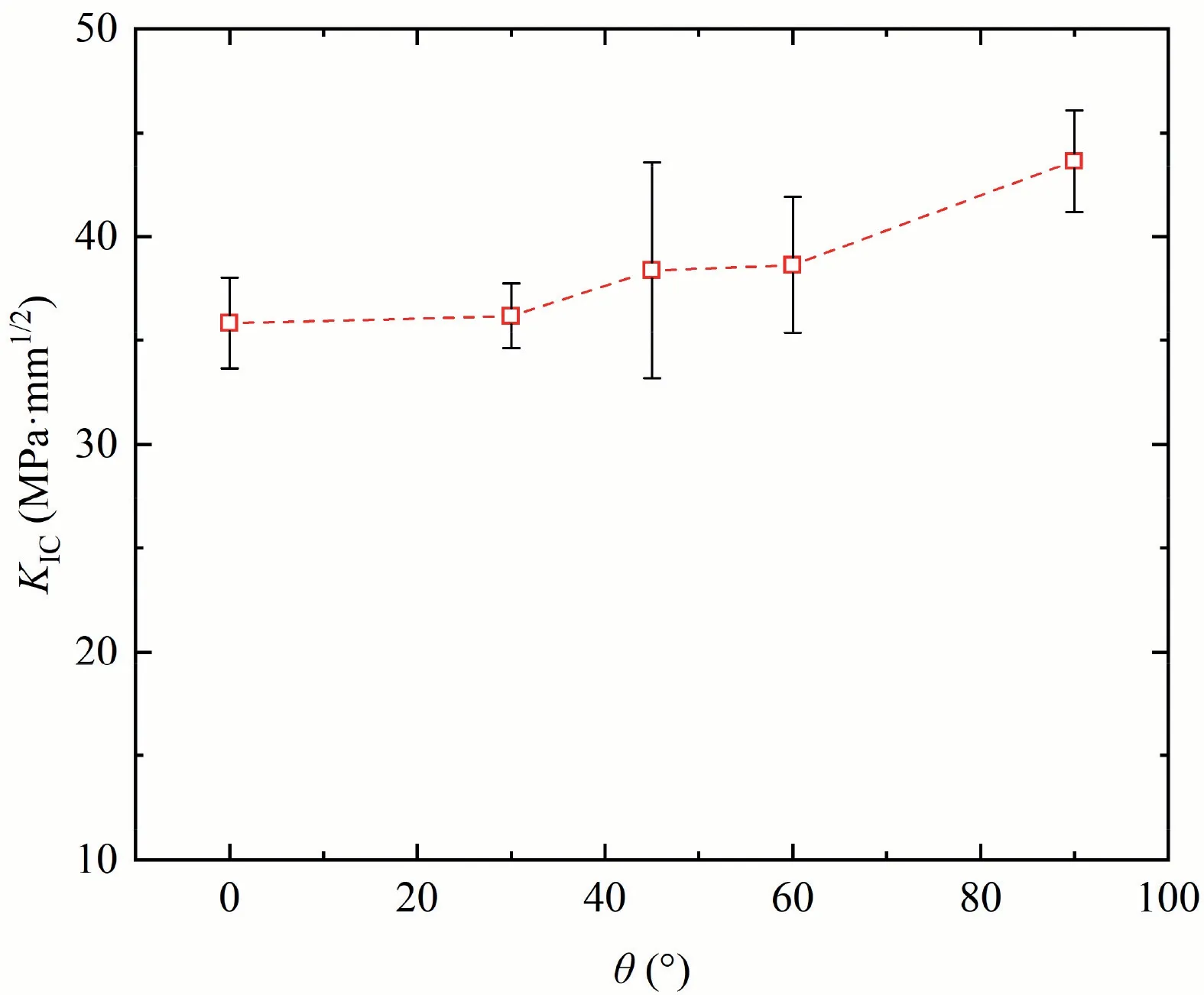
Fig.8.Fracture toughness corresponding to different bedding angles.
Fig.7c presents the variation of peak load for different θ values.The average peak load and standard deviation of peak load are listed in Table 2.Although the experimental results are relatively discrete, it is apparent that the peak load increases with θ approximately,as shown in Fig.7c.The average peak load in 0°group was approximately 80% of that in 90°group.Result of 45°group was the most discrete,with a standard deviation of 20.56 N,accounting for 13.6% of the corresponding average peak load.Considering the heterogeneity of rock materials and the small size of the specimen,we believed that the experimental results were reasonable.
3.2. Fracture toughness corresponding to different θ values
Stress intensity factor KIis an important index related to crack initiation and propagation.In the framework of fracture mechanics,the critical stress intensity factor is defined as the fracture toughness KIC.To discuss the effect of shale bedding on fracture toughness,linear elastic fracture mechanics was adopted to determine the mode I fracture toughness of Longmaxi shale.For simplicity,we considered the Longmaxi shale as a continuous,homogeneous and isotropic material.According to the handbook for stress analysis of crack(Tada et al.,2000),mode I fracture toughness for single edge notched three-point bending specimen could be determined by.
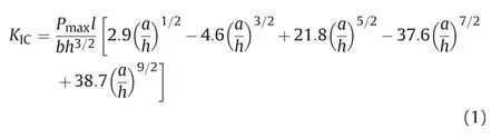
where Pmaxis the peak load; l is the effective bean span(l=20 mm);a is the length of the preset notch(a=4 mm);and b and h are the thickness and width of the specimen,respectively.

Fig.9.Measurement of crack length and its variation:(a)Merged SEM images and the cracking path extracted from SEM images;(b)Relationship between crack length and loading time;and(c)Relationship between crack length and bedding angle.
Fracture toughness KICcorresponding to different bedding angles is presented in Fig.8.Fracture toughness gradually increased with the bedding angle θ.Similar to the peak load,the fracture toughness in a single test group was discrete,due to the heterogeneity of Longmaxi shale.Discreteness of fracture toughness was slightly different from that of peak load,because the fracture toughness was determined by multiple factors,i.e.peak load,height and thickness of the specimen. The average fracture toughness had a minimum value at the angle of 0°and it reached a maximum value at the angle of 90°,which is in line with the research on Mancos shale by Chandler et al.(2016).The variation of KICindicated that fracturing was more likely to occur,which was proved by the laboratory observations.When the prefabricated notch was parallel to the bedding plane,the crack grew rapidly along the bedding plane.When the notch was perpendicular to the bedding plane,the crack would propagate through the bedding plane.This could be observed from different crack propagation patterns with several inflections in crack propagation paths.The changes of KICwith bedding angle should be taken into consideration and it is very important for effective hydraulic fracturing and stability of shale gas shaft.
3.3. Crack length
When loading was completed,the cracking path was recorded by taking several overlapped SEM images at a magnification of×100.The crack is black on SEM images,as shown in Fig.9a.Using the image processing toolbox in MATLAB(MathWorks,2014),we extracted the main cracking path by threshold-based segmentation technique(Gonzalez and Woods,2018).The extracted main cracking path was shown in Fig.9a.By counting the pixels of the cracking path and the scale bar which was 100 μm on SEM images,we obtained the crack length a.Fig.9b shows the crack length of specimen 30°-3 during loading,with respect to loading time.The scale bar in the SEM image was 100 μm long,represented by 50 pixels.Therefore,the accuracy of the method was 2 μm/pixel,which was precise enough to calculate the crack length.The crack length was close to 0 mm until the loading increased to crack initial load,and then it increased significantly.The crack velocity was about 0.017 mm/s.
Fig. 9c shows the relationship between crack length and bedding angle.Although the crack lengths in the same bedding angle group were scattered,the average crack length gradually increased in the range of 0°-60°,and then decreased when the bedding angle increased from 60°to 90°.The main cracks generally propagated through the bedding plane for the notch having angles of 30°,45°and 60°with respect to the bedding plane.The main cracks propagated along a horizontal path for a specimen with bedding angles of 0°(the notch is parallel to bedding plane)and 90°(the notch is perpendicular to bedding plane).
3.4. Fracture energy
The total energy W required to induce rock failure is represented by the area below the load-displacement curve for a single specimen,which represents the work done by the applied load P(Hillerborg,1985):

Fig.10.Variations of(a)W and(b)GF with respect to bedding angle.
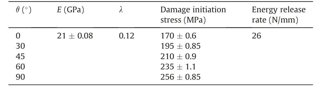
Table 3 Material parameters used in the numerical model.

where δfis the central deflection of the specimen when final rupture occurs.The fracture energy GFis defined as the energy required to create a unit area of fracture surface(Guo and Gilbert,2000):

Fig.11.Schematic diagram of the bilinear traction-separation law.The maximum traction Tmax states the damage initiation criterion,and Gc expresses the critical energy release rate for damage evolution and is equal to the total area of the triangle.

Fig.12.Comparisons between experimental and numerical results:(a)Inclined beddings,and(b)Vertical and horizontal beddings.


Fig.13.Contour plot of maximum principal stress(in MPa)showing crack propagation in 60°bedding angle model at peak load.
where Aligis the area of ligament,determined by crack length a and the thickness of specimen.
Fig.10a shows the total energy W for different test groups.The energy W increased by 48.7% from 1.94×10⁻³J in 0°group to 2.89×10⁻³J in 60°group and then it decreased slightly to 2.85×10⁻³J.Variation of fracture energy GFwith respect to the bedding angle is shown in Fig.10b,which is different from that of energy W.The fracture energy GFbarely changed in the range of 0°-30°and 60°-90°,which were approximately 74 J/m2and 90 J/m2,respectively,because the trends of energy W and the crack length were similar.The fracture energy GFincreased by 22% from 30°case to 60°case.The trend of fracture energy GFwas different from that of the energy W,because the crack length slightly decreased,which resulted in a decreasing fracture surface.
4. Numerical modeling of shale specimen with different bedding angles
4.1. Model formulation
The finite element models of single edge notch bending(SENB)specimens were created in the commercial software ABAQUS.For computational efficiency,the two-dimensional(2D)plane stress elements(CPS4)were used in the finite element model with displacement-controlled boundary conditions.A 4 mm pre-crack was inserted to the mid-bottom long edge of the 25 mm×10 mm(length×width)full-size model.The beam span was 20 mm long.Five bedding orientation fracture models with regard to the crack propagation direction were studied,including the vertically bedding,horizontally bedding,and obliquely bedding SENB models(θ=30°,45°and 60°).The XFEM coupled with anisotropic CZM was developed to capture fracture of shale with different bedding angles.
The XFEM technique adopts the partition-of-unity method and expands the piecewise polynomial function space from conventional finite element method into extra“enrichment functions”to model crack propagation,which has been implemented within ABAQUS.It is capable of resolving arbitrary displacement discontinuities due to cracking,without knowing a priori cracking path in the context of bedding orientations.The method also permits a crack to be located inside a finite element.As a result,it can readily handle an evolving crack plane and solution-dependent crack propagation direction without remeshing during simulations.
The material behaviors are assumed isotropic linear elastic before fracture,with the elastic modulus and Poisson’s ratio given in Table 3.To model fracture behaviors,an anisotropic CZM was developed to characterize the separation of fracture surfaces ruled by an irreversible traction-separation cohesive law under different bedding angles.The bilinear traction-separation law is adopted in this study(Fig.11),which has been used widely to model brittle fracture(Dahi Taleghani et al.,2018;Yang et al.,2019):

where K denotes the slope of the initial elastic stiffness,δfrepresents the separation at complete rupture,and D is a damage variable to indicate the degradation of material stiffness.
The anisotropic CZM was developed to capture the effects of bedding angles.Specifically,two damage initiation criteria were implemented through the user subroutine UDMGINI in ABAQUS(Li et al.,2018;Ghandriz et al.,2020).A material orientation was defined to reflect the bedding orientation in the local x-direction of each finite element.Anisotropic cohesive damage initiation and evolution criteria were then utilized to model fracture along with the local bedding orientations (weak planes). To resolve the possible cases of off-axis crack propagation,the maximum principal stress (MAXPS) criterion was also proposed. The failure criteria for weak plane and the MAXPS are defined below:
Failure criterion 1(for the weak plane):

Failure criterion 2(for MAXPS):

where σijdenotes the stress component in local material orientations;σpis the MAXPS;Twi(i=I,II and III)is the maximum strength in the three fracture modes of the weak plane;Tpis the maximum value for MAXPS;and〈〉is the Macaulay bracket operator used to avoid the compressive loading effects,defined as

where σnis the cohesive traction in the normal(mode I)direction.
In this study,for simplicity,all the maximum strengths(Twi)were presumed the same as Tw.
4.2. Results of numerical models with different bedding angles
Determination of material parameters is important for accurate model predictions.The CZM parameters for the cohesive law were calibrated from experimental data at different bedding angles,which are summarized in Table 3.Fig.12 demonstrates the comparisons between the numerical and experimental results.Overall,the numerical predictions agreed well with the experimental results,which validated the numerical models in capturing shale fracture under different bedding angles.

Fig.14.The cracking paths for shale specimens with different bedding angles:(a)Specimen 0°-3,(b)Specimen 30°-3,(c)Specimen 45°-3,(d)Specimen 60°-3,and(e)Specimen 90°-1.
Fig.13 shows the MAXPS contour plots for 60°bedding angle model at the peak load.The crack kinking influenced by the bedding angles was observed with more widespread stress distributions.It should be noted that the numerical model did not take the porosity and the microstructure into consideration but used anisotropic CZM to capture the effects of local bedding angles.Indeed,Table 3 shows that all the material properties(including energy release rate)are the same for models with different bedding angles except the damage initiation stress.A more refined model based on local porosity and microstructures could possibly improve the accuracy and capture the variations in damage initiation stress,which will be considered in the future.
5. Failure process and fracturing mechanism of longmaxi shale

Fig.15.Different intergranular fracture modes of shale specimen 60°-1.
Fig.14 shows the typical SEM images of cracking patterns for specimens with different bedding planes.Cracking paths in all test groups consisted of main crack and several microcracks along the weak bedding plane.The main crack of specimen 0°-3(Fig.14a)propagated in a small angle of 9°from the preset notch.With the increasing bedding angle,the angle between the main crack and the horizontal notch gradually increased from 19°to 56°.It was interesting that inflection points could be observed on the surfaces of specimens with the bedding angles of 45°and 90°(Fig.14 c and e).The main crack might propagate at a certain angle with the horizontal notch(or the bedding plane),but there were some inflection points when the angle between notch and bedding plane was different.From the local enlarged image in Fig.14,it could be found that there were a few microcracks near the main crack.These microcracks were in different directions due to the different scales of bedding and shale structure.Microcracks can form an interconnected pore system in shale(Ma et al.,2016),which is helpful to increase the production of shale gas.Generally,micro-fractures in rocks can be summarized into three categories: intergranular fracture,transgranular fracture,and coupled intergranular and transgranular fracture(Zuo et al.,2017).In this context,as shown in Fig.15a,most of the fractures were intergranular.When the crack met large sedimentary particles,it grew in the direction oblique to the original cracking path,dominated by the particles.But the main crack still propagated along the original path until the specimen failed(Fig.15b).
The differences between macro-fracture parameters of Longmaxi shale reflected the diversity of fracturing mechanism.The fracturing mechanism of Longmaxi shale with different bedding angles was analyzed.The peak load,fracture toughness and fracture energy generally increased with the increase in bedding angle θ,but the crack length and energy W gradually increased with the bedding angle ranging from 0°to 60°,and then dropped slightly within the bedding angle of 60°-90°.The angle between the preset notch and the cracking path increased with bedding angle,characterized by the inflection points in Fig.14.Therefore,it can be conclusive that the peak load increases with the increasing bedding angle.

Fig.16.Crack initiation position with different curvatures at the tip of notch.
The orientation of the main crack varied with the bedding angle,resulting in changes in crack length(Fig.9c).The difference in the location of bedding planes resulted in a variety of cracking path,which exerted great effects on cracking patterns.Fig.16 shows the notch tips after failure at a magnification of×150.Crack initiated at the position with a larger radius of curvature due to the effects of stress concentration and also in the weak cementation between quartz and calcite grains,according to the principle of minimum energy dissipation(Zhou et al.,1997).
6. Analysis of effect of sedimentary particle
To investigate the effect of large sedimentary particles on crack behaviors,a single edge notch tension model with single-particle inclusion was created in ABAQUS. No bedding plane wasconsidered in the numerical model since it merely focused on the influence of particle.The 2D plane stress elements(CPS4)were used for computational efficiency and only the MAXPS criterion was used.The mechanical and fracture properties of shale(matrix)and particle(inclusion),as well as their interfaces,are listed in Table 4.
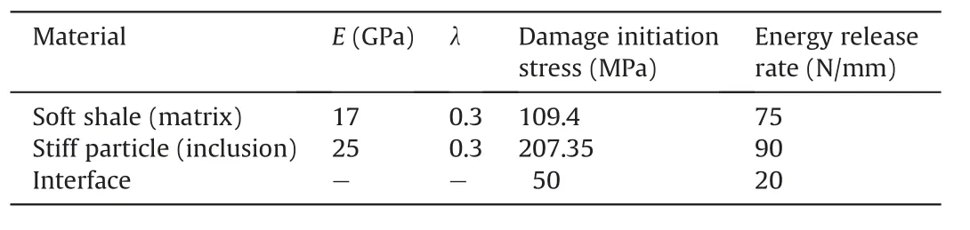
Table 4 Material parameters for the soft shale(matrix),stiff particle(inclusion),and interface properties.

Fig.17.Crack propagation in shale with a single sedimentary particle:(a)-(e)PHILSM contour plots showing the cracking process,and(f)Experimental result.

Fig.18.MAXPS contour plots for fracture simulations in shale(a)With a single stiff particle,and(b)With no particles.

Fig.19.Simulation results for shale with and without stiff particle.
The cracking process was illustrated in PHILSM contour plots at different simulation stages and compared with the SEM image,as shown in Fig.17.The PHILSM variable is the signed distance function of the crack surface for better visualization of the cracking path.The numerical model predicted crack deflection around the sedimentary particle and restoration to pre-crack direction after passing the particle,which was similar to the observation in the laboratory test.It should be noted that the interface between shale and particle played a significant role,where a much weaker fracture property(in Table 4)was selected to guide the crack propagation along with the shale-particle interface. This is also consistent with the physical reality that the interface is usually weak and prone to crack growth.The effect of sedimentary particle was further studied by comparing the results of the shale model with and without stiff particle.Fig.18 shows the MAXPS contour plots for both cases.There were more stress concentrations around the particle. The load-displacement curves were plotted and compared in Fig.19.It was found that the existence of particle significantly increased the macroscopic peak load as well as the fracture toughness.This can be explained by the crack deflections which consume more fracture energy.Overall,the numerical study facilitates our understanding of the effects of bedding angles and sedimentary particles on crack propagation and macroscopic fracture response.
7. Conclusions
This paper experimentally and numerically studied fracture characteristics of the outcrop shale sampled from Longmaxi,Chongqing,China.The cracking process of Longmaxi shale was observed using SEM with a loading system,and variations of the mechanical parameters of Longmaxi shale were analyzed with respect to the bedding angle.The XFEM coupled with anisotropic CZM was developed to simulate the cracking process,which agreed well with the experimental results.Besides,the effect of particle inclusion on crack behavior was studied numerically using a single edge notch tension model.The findings are summarized as follows:
(1)As the anisotropy of shale and the number of weak bedding planes within specimen varied,the experimental results of shale with different bedding angles are scattered,while the general tendency could be observed through the average values.The peak load,fracture toughness and fracture energy of shale gradually increased with the bedding angle until the crack length and the energy reached a maximum at an angle of 60°,after which they slightly decreased.
(2)The main cracking path accompanied by several microcrack branches could form an interconnected crack system.The bedding plane had a significant effect on the fracture pattern of Longmaxi shale.Cracks propagated along weak cementation positions and bedding planes.When the crack encountered large sedimentary grain,it tended to propagate around the grain and branch at the weak bedding plane.Therefore,the effects of bedding should be considered in the design of hydraulic fracturing in shale gas extraction.
(3)An anisotropic CZM coupled with XFEM was developed and validated to capture cracking of shale with different bedding angles and large sedimentary particles.A feature of the model was that both the anisotropic damage along bedding directions (weak planes) and the MAXPS failure were considered to determine the crack propagation.The effect of sedimentary particles was also studied numerically and it showed a good consistency with experimental findings.Both the peak load and fracture toughness increased due to the crack deflections around sedimentary particles.
Declaration of Competing Interest
The authors wish to confirm that there are no known conflicts of interest associated with this publication and there has been no significant financial support for this work that could have influenced its outcome.
Acknowledgments
This study was financially supported by National Natural Science Foundation of China(grant No.41877257),Beijing Outstanding Young Scientist Program(Grant No.BJJWZYJH01201911413037),Shaanxi Coal Group Key Project(Grant No.2018SMHKJA-J-03)and Yueqi outstanding scholar Award Program by China University of Mining and Technology(Beijing),China.
 Journal of Rock Mechanics and Geotechnical Engineering2020年2期
- Journal of Rock Mechanics and Geotechnical Engineering的其它文章
- Sugarcane press mud modification of expansive soil stabilized at optimum lime content:Strength,mineralogy and microstructural investigation
- Dynamic compression characteristics of layered rock mass of significant strength changes in adjacent layers
- Reliability analysis of earth dams using direct coupling
- Centrifuge model test and numerical interpretation of seismic responses of a partially submerged deposit slope
- Anisotropic surface roughness and shear behaviors of rough-walled plaster joints under constant normal load and constant normal stiffness conditions
- Determination of full-scale pore size distribution of Gaomiaozi bentonite and its permeability prediction