Shaped charge penetration into high-and ultrahigh-strength Steel-Fiber reactive powder concrete targets
Qing-qing Xio ,Zheng-xing Hung ,*,Xudong Zu ,Xin Ji ,Qi-feng Zhu ,Wei Ci
a School of Mechanical Engineering,Nanjing University of Science and Technology,Xiaolingwei 200,Nanjing,210094,China
b China South Industries Group Corporation,Chongqing,400039,China
Keywords:Shaped charge Reactive powder concrete target Penetration Radial drift velocity Gap effects
ABSTRACT Experiments on shaped charge penetration into high and ultrahigh strength steel-fiber reactive powder concrete(RPC)targets were performed in this paper.Results show that the variation of penetration depth and crater diameter with concrete strength is different from that of shaped charge penetration into normal strength concrete(NSC).The crater diameter of RPC is smaller than that of NSC penetrated by the shaped charge.The jet particles are strongly disturbed and hardly reach the crater bottom because they pass through the narrow channel formed by jet penetration into the RPC.The effects of radial drift velocity and gap effects of jet particles for a shaped charge penetration into RPC target are discussed.Moreover,a theoretical model is presented to describe the penetration of shaped charge into RPC target.As the concrete strength increases,the penetration resistance increases and the entrance crater diameter decreases.Given the drift velocity and narrow crater channel,the low-velocity jet particles can hardly reach the crater bottom to increase the penetration depth.Moreover,the narrow channel has a stronger interference to the jet particles with increasing concrete strength;hence,the gap effects must be considered.The drift velocity and gap effects,which are the same as penetration resistance,also have significant effects during the process of shaped charge penetration into ultrahigh-strength concrete.The crater profiles are calculated through a theoretical model,and the results are in good agreement with the experiments.©2020 China Ordnance Society.Production and hosting by Elsevier B.V.on behalf of KeAi Communications Co.This is an open access article under the CCBY-NC-ND license(http://creativecommons.org/licenses/by-nc-nd/4.0/).
1.Introduction
Concrete is the most commonly used construction material.In recent years,a significant growing trend in the utilization of concrete has occurred because of its superior performance over conventional materials[1].With the development of concrete technology,high-performance concrete(HPC)and ultrahighperformance concrete have been widely used in the construction of high-rise buildings,bridges,highways,airport runways,largespan buildings,offshore buildings,and structural repairs[2-6].Meanwhile,the high-and ultrahigh-strength concrete which possess great resistance to impact loading have also been used in military protection engineering to improve antiballistic ability and enhance the protective properties of structures.
The ballistic and protective performance of normal-strength concrete(NSC)under impulsive loading,such as blast loading[7-10],projectile impact[11-14],and shaped charge penetration[15-20],have been widely investigated in the last decades.The HPC,which is of higher strength and better durability and has been widely used in various structures,has recently attracted considerable interest owing to its performance under impulsive loading.Ngo[21]investigated the blast resistance of ultrahigh strength concrete(UHSC)panels made of reactive powder concrete(RPC)against an explosion of 5 t hexoline(equivalent to 6 t of TNT)at the standoff distances of 30 m and 40 m.The RPC panels performed extremely well,whereas the panel made of NSC was breached;results revealed that RPC can also be a very effective material for blast resistance.Yi[22]evaluated experimentally the blastresistant capacity of reinforced UHSC and RPC panels under blast loading.The results indicated that the ultrahigh compressive strengths of UHSC and RPC conferred greater resistance to blast loading than that of NSC.Remennikov[23]analyzed the breach diameters of NSC and HSC panels subjected to contact charge detonations.The breach diameter for HSCpanel is smaller than that produced for NSC panel with the same explosive charge mass.Sovj'ak[24]compared the resistances of ultrahigh-performance fiber-reinforced concrete(UHPFRC),conventional fiber reinforced concrete(FRC),and NSC subjected to the deformable projectile impact.That study revealed that UHPFRC has considerably better resistance to projectile impact,and that containing 2%of fibers by volume has optimal resistance.Zhang[25,26]found that the compressive strength and size and strength(hardness)of the coarse aggregate affect the projectile impact resistance of HSC.Meanwhile,Zhang[25]reported that the penetration depth of projectile impact decreases with an increase in the compressive strength when below a certain level,and further increases in the compressive strength does not have a significant effect on the penetration depth.The high-strength fiber-reinforced concrete with a compressive strength of~100 MPa appears to be most efficient in the protection against projectile impact.Liu[27]observed that steel fibers incorporated into UHPC targets can provide higher shear strength and toughness,which improved the impact resistance regarding depth of penetration(DOP)against the projectile penetration.
Given its high strength,high toughness,excellent ductility,and good energy absorption,HSC has been confirmed to have better resistance than NSC subjected to blast and projectile.The shaped charge jet,which generally considers that the penetration depth is less affected by the target strength,can be effective against HSC target.How ever,the diameter of the crater generated by shaped charge jet penetration is very sensitive to the target strength[15].This is not good for tandem warhead,which requires a large diameter for the second stage to pass through.Resnyansky[28-30]studied the protection performance of UHPC compared with that of plain concrete subjected to the shaped charge jet,and found that the UHPC demonstrated advanced protective characteristics compared with the plain concrete.Meanwhile,Resnyansky[28]indicated that penetration is possible for HSC subjected to the advanced shaped charge design.Esteban[31]compared the penetration depths of NSC and UHPC by shaped charge jets,and found that the UHPC does not provide a significant reduction in crater diameters and depths.Hence,the use of UHPC to protect structures against shaped charge attacks is not recommended because UHPC has a higher cost than NSC.Zhu[32]indicated that the penetration depth of shaped charge jet decreases exponentially as the compressive strengths of HSC and UHSC increase at the beginning,and then approximates the limit when the compressive strength approaches 200 MPa.The cavity diameters are not affected by the increasing strength grade.
In the present paper,a total of 12 RPC targets with 4 strength grades,namely,C100,C200,C300,and C400,were prepared,and 8 targets were selected in experiments.A precise shaped charge was used to penetrate the RPC targets at the same standoff.The penetration depth is significantly reduced first and then gradually decreased as the uniaxial compressive strength of RPC increased.How ever,the crater diameter gradually decreased at the entrance and was almost similar to that of the crater bottom with increasing RPC strength.For the authors,these are unexpected results.Thus,the radial drift velocity and gap effects of jet particles were considered during the process of shaped charge jet penetration into HSC.Moreover,the crater profile of the shaped charge jet into HSC was not only affected by the concrete strength but also by the minimum efficient jet velocity and the penetration capability of the jet particles.
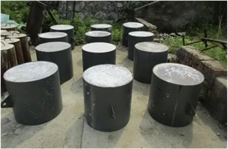
Fig.1.RPC targets.
2.Experimental setup
2.1.Target preparation
The high-and ultrahigh-strength steel-fiber RPC targets with four strength grades,namely,C100,C200,C300,and C400,with steel fiber volumetric ratios of 0%,2%,4%,and 6%,respectively,were prepared.Three targets were processed for each type of reactive powder concrete.Therefore,a total of 12 RPC targets were manufactured(Fig.1).
A steel casing with wall thickness of 6 mm was designed to fill uncured concrete.The casing had an internal diameter of 600 mm and internal height of 600 mm.The material,mix proportions,and manufacturing methods of RPCs are described in a previous work[32].Moreover,three specimens,which were used to test uniaxial compressive strength were made under the same conditions as each target (Fig. 2). The size of each specimen is 160 mm×40 mm×40 mm.The quasi-static three points bending tests performed firstly to obtain the flexural strength.Then,the two pieces of specimen after being broken were used for the uniaxial compression tests to obtain the compressive strength.Finally,eight RPC targets were used in the experiments.The density ρtand uniaxial compressive strength fcof the eight RPC targets are listed in Table 1.
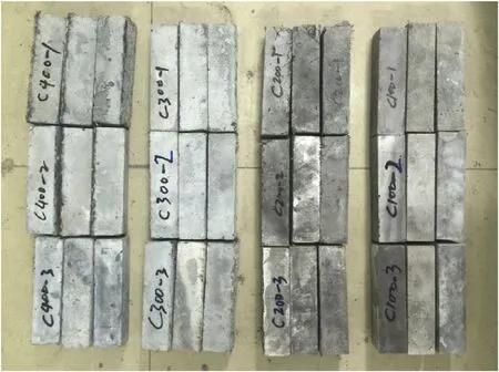
Fig.2.Specimens of RPC targets.

Table 1 Density and uniaxial compressive strength of the RPC targets.
2.2.Shaped charge
A precise shaped charge mentioned in Ref.[33]was used in the experiments.Oxygen-free,high-conductivity copper with purity of 99.99%was used as liner material,and the explosive is JH-2(95%RDX and 5%TNT)with a density of 1.713 g/cm3.A sketch of the shaped charge is shown in Fig.3.The charge has a base diameter of 56 mm and height of 73.3 mm.The conical liner has a cone angle of 60°,wall thickness of 1 mm,and height of 42 mm.
The simulation of the shaped charge jet formation was performed using AUTODYN-2D finite-difference Eulerian code,and the simulation method was verified according to Refs.[15,16].Moreover,the X-ray experiment was performed to determine the parameters of the shaped charge jet.The details of simulation and Xray experiment are published in Ref.[33].Based on the comparison between the experiment and the simulation,the jet parameters,including length,velocity,and diameter,are shown in Fig.4.
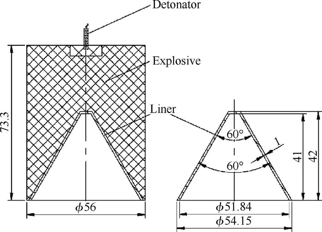
Fig.3.Geometry of shaped charge used in experiments.
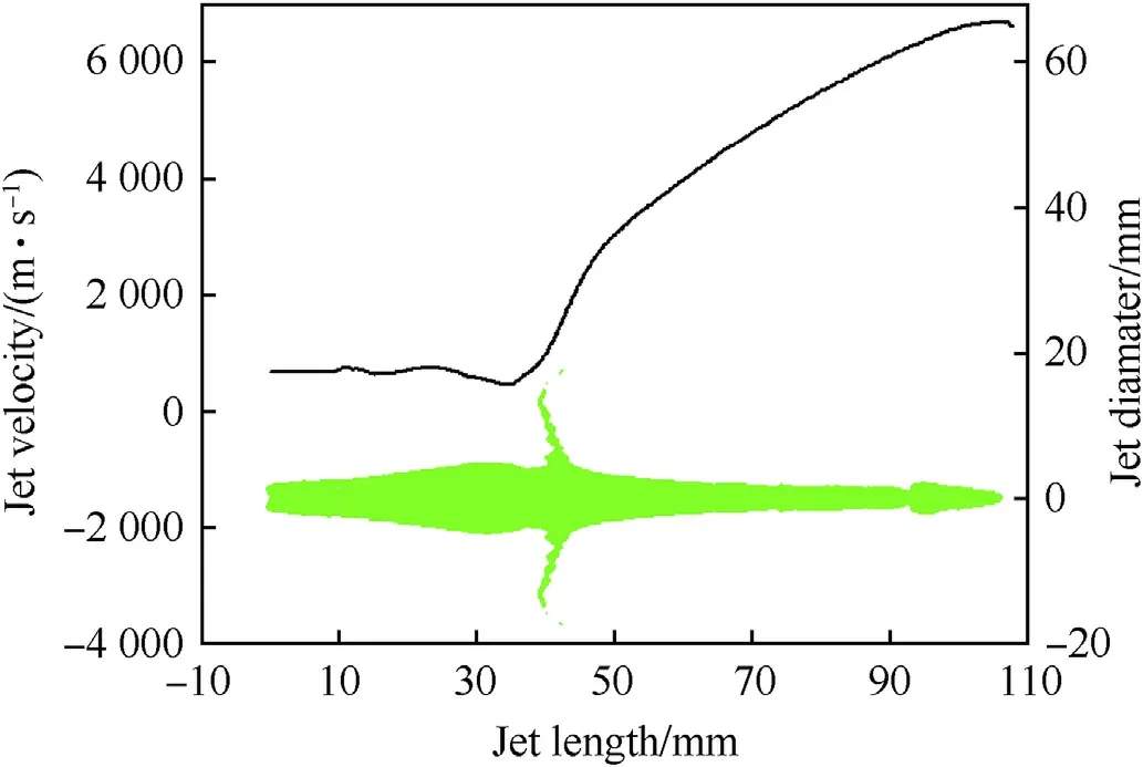
Fig.4.Parameters for the shaped charge jet.
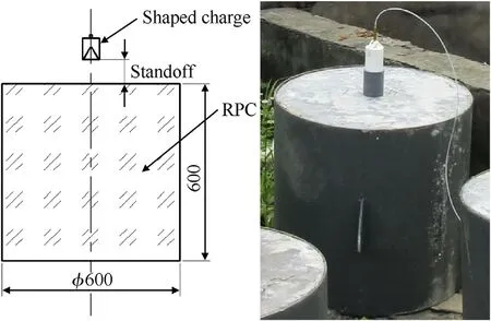
Fig.5.Test device of shaped charge penetration into RPC Targets.
2.3.Experimental setup
The experiments on the precision shaped charges penetrating into RPC targets were performed.A PVC cylinder casing was placed between the charge and the target to ensure that the stand-off(distance between the bottom of the shaped charge and the surface of the target)was 80 mm.The experimental device is shown in Fig.5.
2.4.Experimental results
The eight RPC targets of C100-1,C100-3,C200-2,C200-3,C300-1,C300-3,C400-1,and C400-2 were selected for the penetration depth tests.Moreover,in order to observe the crater profile accurately,the target of each test was drilled along the cross section of the penetration hole,and the concrete core was removed.Fig.6 shows the crater profiles of C100-1,C100-3,C200-2,C200-3,C300-1,C300-3,C400-1,and C400-2 penetrated by shaped charges.
The variation in the penetration depth with uniaxial compressive strength of the RPC targets is illustrated in Fig.7.The penetration depth is significantly reduced as the uniaxial compressive strength of RPC increases from 100.78 MPa to 185.22 MPa.Then,the penetration depth is almost unchanged when the uniaxial compressive strength of RPC increases from 248.36 MPa to 339.07 MPa.The penetration resistance changes little when the uniaxial compressive strength is greater than 200 MPa.
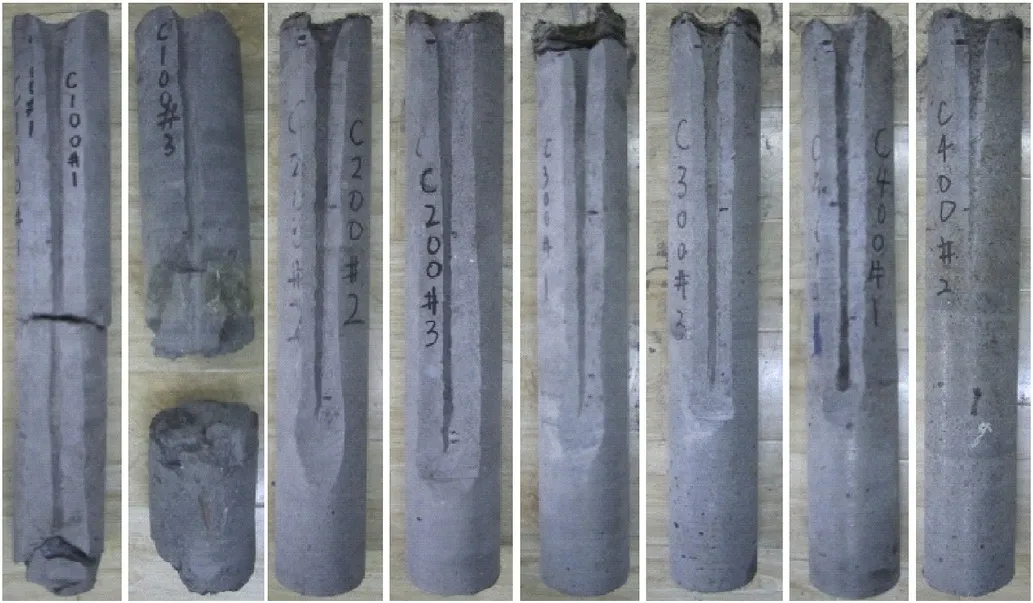
Fig.6.Concrete core removed from RPC target after penetration.
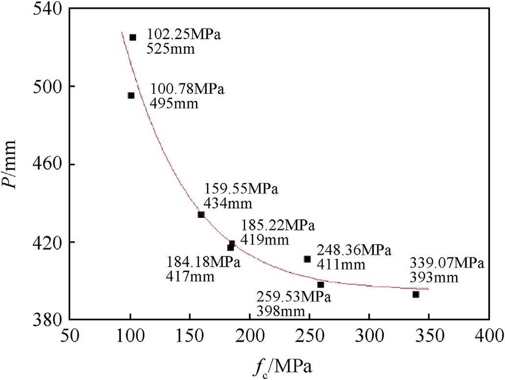
Fig.7.Variation in the penetration depth with uniaxial compressive strength of the RPC targets.
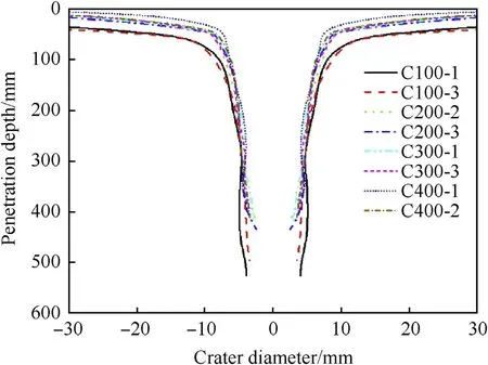
Fig.8.Crater profiles formed by shaped charge penetration into RPC targets with different strengths.
The comparison of the crater profiles formed by the shaped charge penetration into RPC targets with different strengths is illustrated in Fig.8.Obviously,the entrance crater diameter gradually increased with decreasing RPC strength.Surprisingly,the difference in crater diameter gradually decreased with increasing penetration depth for RPCs with different strengths.The diameter of the crater bottom is nearly the same.In other words,the effect of RPC strength on the crater diameter decreases as the jet velocity decreases.How ever,as the jet velocity decreases,the effect of target strength on the penetration and radial crater grow th velocities is even more significant.
A more reasonable explanation is that the diameter of the crater generated by jet penetration decreases with increasing RPC strength,and the low-velocity jet particles can easily impact the crater wall and hardly reach the crater bottom to increase the penetration depth because the jet has a consistently low drift velocity after formation[33-35].Thus,the velocity of the jet particle that finally penetrates into the crater bottom increases with increasing RPC strength.The increase of the minimum efficient jet velocity indicates the reduction of the jet effective length during penetration for UHSC.Moreover,the jet particles are strongly disturbed as they pass through the narrow channel formed by jet penetration into RPC,and the penetration capability of the jet particles that can reach the crater bottom will be greatly reduced.Therefore,as the strength of the RPC target increases,the entrance crater diameter gradually decreases,whereas the minimum efficient jet velocity affecting the diameter of the crater bottom increases;the diameter of the crater bottom remains nearly constant.Moreover,the penetration depth is not only affected by the RPC strength but also by the minimum efficient jet velocity.The radial drift velocity and gap effects of jet particles should be considered during the shaped charge jet penetration into UHSC.
3.Theory
3.1.Radial drift velocity and gap effects
Many researchers found that the jets have a lower radial drift velocity after formation.The drift velocity leads to slightly different trajectory of each particle.The jet particle with a low drift velocity impacts crater wall with ease.Furthermore,the jet particle cannot reach the crater bottom to increase depth because the crater diameter generated by the jet is quite small.Segletes[34]confirmed that jet curvature is the major cause of nonideal jet penetration.He measured the drift velocity of particle jets using Xray radiographs and show ed that the drift velocity increases with increasing jet velocity.Held[35]found that machining accuracy and jet breakup result in the drift velocity.Moreover,the gap distance between jet particles also plays an important role in penetration depth,as well as tumbling and dispersion of jet particles.Chou and Flis[36]considered the influence of the gap distance between jet particles on penetration depth.The actual penetration depth of particulate jet reduces with increasing gap.Hancock[37]regarded the drift velocity and gap effects to present a simple empirical mode.Xiao[33]presented an analytical model to describe the radial drift velocity and gap effects of jet particles.The stand-off curve of shaped charge was calculated by using the model.
During jet formation,machining inaccuracy generates a drift velocity.Moreover,the process of jet breakup is not entirely ductile.Meanwhile,shear and distortion,which cause jet particles to generate a drift velocity,occur during breakup.Thus,the radial drift velocity of particle jets can be described as

where vdis the radial drift velocity of jet particles,vCdis the drift velocity caused by machining inaccuracy,and vBdis the drift velocity caused by breakup.Dimensional analysis method was used to study the effects of axial velocity vj,jet diameter dB,and strain rate ˙εBduring breakup on radial drift velocity[33].The drift velocity caused by machining inaccuracy and breakup is given by

where C1is a constant associated with machining inaccuracy,C2is a constant associated with shaped charge structure,tBis the breakup time of jet particle,and tois the time of virtual origin.The radial drift velocity of particulate jet is given by

Ignoring the transverse movement before fracture,the radial drift distance of a given jet segment at time t can be expressed as

If the jet particle is out of crater profile,then this phenomenon means

where Dcis the crater diameter.The particle will not reach the crater bottom to increase the penetration depth.On the contrary,the penetration of the particle increases the depth.
The penetration depth of particulate jet decreases with the gap distance between increasing jet particles.In the present study,dimensional analysis was also used.Then,the penetration depth of a jet particle,which is related to the relative drift position,relative gap distance,and the properties of the jet and the target,can be obtained as[33].

When δ*rand g*are close to zero,the particulate jet is similar to a continuous jet,and the penetration depth of the jet particle is equal to that of a continuous jet.The jet particle is similar to a single rod when δ*ris close to zero and g*is sufficiently large,and the penetration depth is obtained as

where ξ is the relatively decreased value of penetration depth between the single rod and the continuous jet.Moreover,if the jet particles are strongly disturbed as they pass through the narrow channel formed by jet penetration into UHSC,the value of ξ increases.Moreover,steel fibers in the RPC targets can increase the value of ξ.Thus,the penetration capability of disturbed jet particles decreases.
3.2.Axial penetration and radial crater growth
In order to determine whether or not the jet particles have an impact on the crater wall,the crater profile generated by the shaped charge jet penetration is necessary.The crater profile prediction,which is also applied to calculate the stand-off curve of shaped charge jet into steel target[33],is discussed in Ref.[15].
When the axial penetration velocity is greater than the sound velocity,a stationary shock is formed in front of the jet/target interface.The axial penetration equation is given by

Meanwhile,the final crater diameter equation is given by

As the jet erodes during penetration,jet velocity and penetration velocity decrease.The axial penetration equation when the axial penetration velocity is lower than the sound velocity becomes

and the final crater diameter equation becomes

Moreover,the propagation and attenuation of compaction wave generated by the shaped charge penetration of the target is discussed in detail in Ref.[19].The penetration resistance is considered as the dynamic yield strength of the target.As discussed in Refs.[15,16],the target resistance parameter Rtis obtained from the penetration data using the fitting crater diameter.
4.Calculation and analysis
The radial drift velocity and the gap effects of the precision shaped charge used in experiments were confirmed by the standoff curve of jet penetration into the steel target[33].The values of C1and C2in Eq.(3)are given as 0 and 0.24,respectively.The values of N,ξ,and η in Eq.(5)are given as 1.5,0.2,and 2,respectively.Given the absence of strain hardening in the concrete,thepenetration capability of jet particles into the lower-strength concrete should be higher than that of the penetration of jet particles into steel target.As the strength of the concrete increases,the interaction between the jet particles and the UHSC residue becomes more intense due to the decrease in the crater diameter.This means that the value of ξ should be less than 0.2 when the charge penetrates the lower-strength RPC target and greater than 0.2 when the charge penetrates the higher-strength RPC target.

Table 2 Summary of the shaped charge jet and RPC targets.
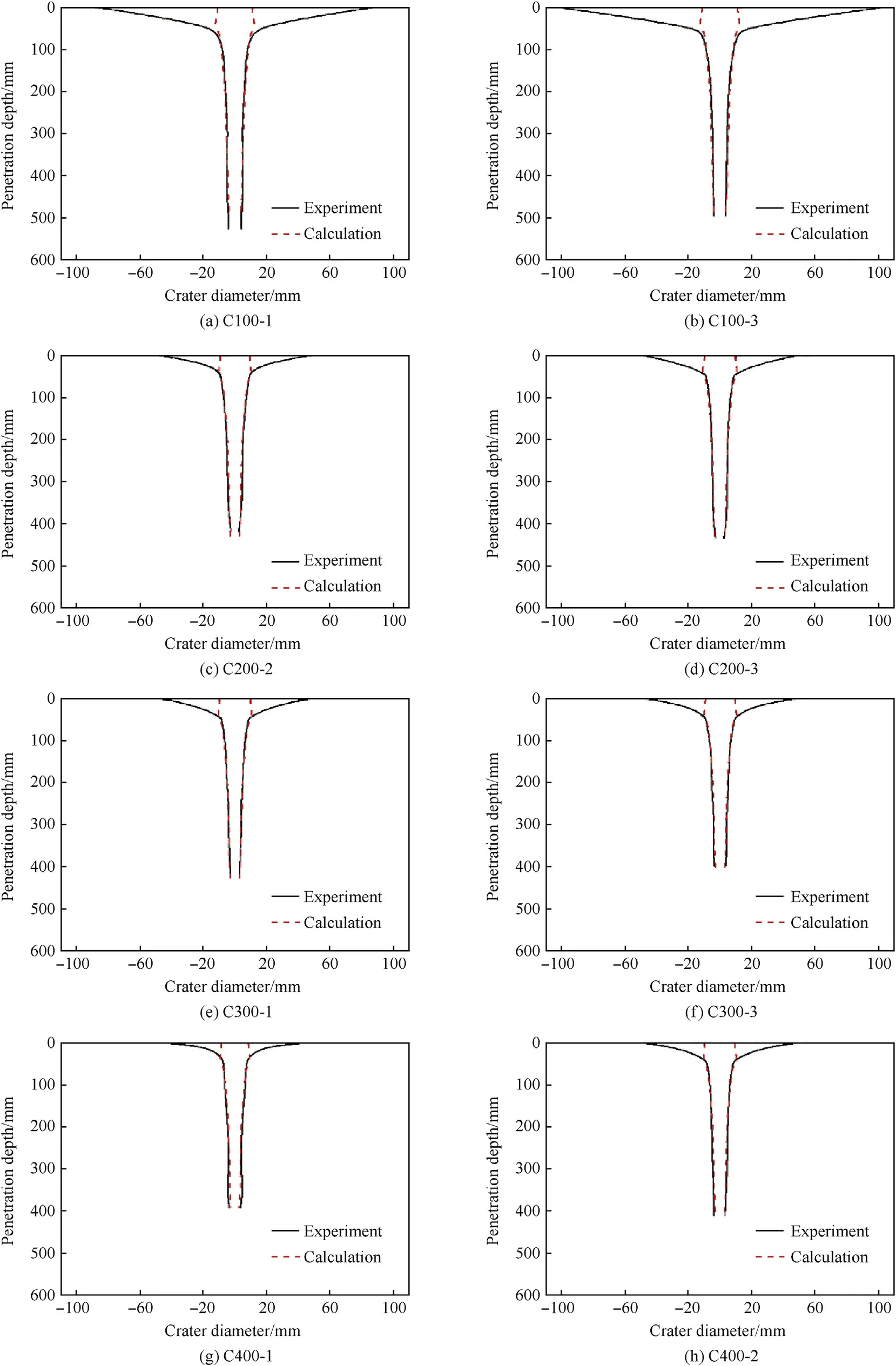
Fig.9.Comparison of the crater profiles between calculations and experimental.
Meanwhile,the density and uniaxial compressive strength of each RPC target are tested in Section 2.1.The C0and λ values for the RPC target are determined basing on Ref.[38]and are discussed in detail in Ref.[32].Moreover,the penetration resistance Rtcan be obtained by fitting the crater profile[15,16,19,33].Table 2 summarizes the parameters of the shaped charge jet and RPC targets.The minimum efficient jet velocity vm,as well as penetration depth from calculations Pcand experiments Pe,are also listed in Table 2.The details of the calculation method,including the determination of the jet fracture time,are shown in Refs.[15,19,33].The jet breakup time is given by Ref.[39].

with

where cbis a constant for identical materials.D0is the jet diameter,and 1/t*is the jet velocity gradient.
Moreover,the comparison of the crater profiles is illustrated in Fig.9.The calculation results of penetration depth and crater diameter are in good agreement with the experimental results.The penetration resistance is approximately 2 times that of the uniaxial compressive strength of the RPCs when it is less than 185.22 MPa.When the uniaxial compressive strength is greater than 185.22 MPa,the penetration resistance is approximately 1.5-1.6 times that of the uniaxial compressive strength of the RPCs.Moreover,the value of ξ is approximately 0.1 for C100 RPCs.As the strength and the volumetric ratio of the steel fiber of RPC increase,the value of ξ increases to 0.3 for C200,C300,and C400 RPCs.This finding indicates that the penetration capabilities of disturbed jet particles penetrating the C200,C300,and C400 RPCs are less than that of the disturbed jet particles penetrating the C100 RPCs.Under the effect of the radial drift velocity,the minimum efficient jet velocity increases as the RPC strength increases due to the decrease of the entrance crater diameter.Therefore,the diameter of the crater bottom is nearly the same because the jet impact velocity is higher for the higher strength RPCs at the crater bottom.
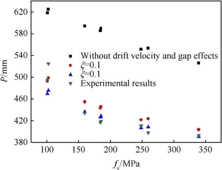
Fig.10.Comparison of penetration depth under different conditions with the experimental results.
The penetration depth without drift velocity and gap effects,ξ=0.1,ξ=0.3,and experimental results was compared,as shown in Fig.10.As can be seen,the penetration depth is significantly higher than the experimental result without considering drift velocity and gap effects.The radial drift velocity and the gap effects should be considered during the shaped charge jet penetration into UHSC.
5.Conclusions
The experiments of shaped charge jet penetration into high and ultrahigh strength steel-fiber RPC targets show that the entrance crater diameter gradually increased,while the crater bottom diameter is almost the same as the RPC strength decreased.Moreover,the penetration depth initially decreased,and then is almost unchanged with the increasing RPC strength.
In order to explain the experimental phenomenon,the radial drift velocity and the gap effects were considered during the shaped charge jet penetration into RPCs.As the strength of the concrete increases,the diameter of the crater generated by shaped charge jet penetration into the concrete decreases,especially the HSC and UHSC.The low-velocity jet particles can hardly reach the crater bottom to increase the penetration depth due to the drift velocity and narrow crater channel.The diameter of the crater bottom is almost the same because the minimum efficient jet velocity is higher for the higher-strength RPCs.Moreover,the penetration capability of the disturbed jet particles is affected by the interaction between the jet particles and the UHSC residue.
Acknowledgment
This work was supported by the Natural Science Foundation of China through Grant No.11702144.
- Defence Technology的其它文章
- A review of dual-spin projectile stability
- A new look on the electric spark sensitivity of nitramines
- Damage assessment of the target area of the island/reef under the attack of missile warhead
- Physical and damping properties of kenaf fibre filled natural rubber/thermoplastic polyurethane composites
- Effect of transverse compression on the residual tensile strength of ultrahigh molecular weight polyethylene(Dyneema®SK-76)yarns
- Design of infrared camouflage cloak for underground silos

