Effect of transverse compression on the residual tensile strength of ultrahigh molecular weight polyethylene(Dyneema®SK-76)yarns
Karan Shah ,Subramani Sockalingam ,*
a McNAIR Center for Aerospace Innovation and Research,University of South Carolina,SC,USA
b Department of Mechanical Engineering,University of South Carolina,SC,USA
Keywords:Polymer fibers Compression Tensile strength
ABSTRACT Ballistic impact induces complex stress states on fiber-based armor systems.During impact fibers undergo multiaxial loading which includes axial tension,axial compression,transverse compression,and transverse shear.Transverse compression induced by the projectile leads to permanent deformation and fibrillation of fibers resulting in degradation of material tensile strength.Previous work(Sockalingam et al.Textile Res.J2018)has shown a reduction of 20%in the tensile strength of Dyneema®SK76 single fibers subjected to 77%nominal transverse compressive strains.Experimental investigation of quasistatic transverse compression on Dyneema®SK-76 yarns,unconstrained in the lateral direction,indicate an average of 4%reduction in tensile strength of yarns compressed to 77%nominal strains.In this work we use finite element modeling techniques to understand the difference in residual tensile strength between single fibers and yarns observed in laterally unconstrained transverse compression experiments.Finite element study of the transverse compression response of single fibers and yarns indicate that local strains developed in fibers within the yarn are much lower than the local strains developed in single fibers subjected to a given nominal strain and may explain the less reduction in strength observed in yarns.©2020 China Ordnance Society.Production and hosting by Elsevier B.V.on behalf of KeAi Communications Co.This is an open access article under the CCBY-NC-ND license(http://creativecommons.org/licenses/by-nc-nd/4.0/).
1.Introduction
Ultrahigh molecular weight polyethylene(UHMWPE)is a linear flexible polymer of C2H4molecules.When C2H4molecules are drawn using a gel-spun process,they result in a highly crystalline and oriented chain of molecules along the fiber direction.As compared to a melt crystallized block of the same molecules that results in an entangled spaghetti type molecular structure,the gel spinning and drawing process results in a long chain of parallel molecules in a crystal lattice.Such a crystal structure enables UHMPWE fibers to offer a combination of low density,high strength and high stiffness,making them suitable for armor systems.UHMWPE fibers are used in the form of textile fabrics and composites in ballistic applications[[1,2]].Ballistic impact on these fiber-based systems results in complex loading of fibers and yarns at high strain rates[3-6].Fibers and yarns are loaded in different deformation modes including axial tension,axial compression,transverse shear, and transverse compression. Transverse compression induced by the projectile causes permanent deformation and fibrillation of fibers[7-9]near the region of impact.This causes degradation of material tensile strength eventually leading to failure.Axial tensile fiber properties are key contributors to the ballistic performance[10].Thus,it is important to understand the influence of multiaxial loading on fiber tensile strength.
Previous studies on the effect of transverse compression on tensile strength have focused on single fibers.Experiments on Kevlar®KM2 single fibers by Sockalingam et al.[11]show a decrease in tensile strength with an increase in the amount of applied transverse compression.Sockalingam et al.also experimentally investigated the quasi-static and high strain rate transverse compression response of Dyneema®SK-76 single fibers[7,9].Their results show a non-linear stress-strain response of Dyneema®SK-76 fibers in transverse compression at both low and high strain rates.A recent study by Golovin and Phoenix[12]reports a reduction of about 44%and 25%in the tensile strength of Dyneema®SK-76 single fibers that are transversely compressed by hand method and machine roll method respectively.Experimental results from a study by Thomaset al.[[13,14]]show a 20%reduction in the Q-Stensile strength of Dyneema®SK-76 fibers compressed at average nominal strains of 77%.

There are limited investigations in literature on the transverse compression response of individual yarns as compared to single fibers.In our earlier work,we have experimentally studied the effect of quasi-static transverse compression on Dyneema®SK-76 yarns[15].A brief summary of the experimental procedure and results are presented in the next section.In this study,we extend our previous work using finite element modeling techniques to better understand the influence of transverse compression on Dyneema®SK-76 yarns.We aim to understand the differences in the residual tensile strength of yarns and single fibers observed in our experiments.We model the transverse compression response of single fibers and yarns at both quasi-static and high strain rates to investigate the true stress-strains developed in single fibers and yarns during transverse compression.Finally,we make comparisons between simulation and experimental results to understand the differences in transverse compression response of yarns and single fibers.
2.Experimental observations
This section summarizes the experimental results of transverse compression of Dyneema®SK-76 single fibers and yarns.We first report the results from literature for Dyneema®SK-76 single fibers followed by experimental results from our previous work[15].The influence of transverse compression on the residual tensile strength of single fibers and yarns is measured using two experiments.First,the single fibers or yarns are compressed in the transverse direction.Then the compressed single fibers or yarns are pulled in axial tension to measure the residual tensile strength.
Thomas et al.[13]have studied the influence of transverse compression on single fiber at high strain rates.Their results indicate a 20%reduction in the tensile strength of single fibers compressed to 77%average nominal strains.For tensile experiments,nominal stress and nominal strain is defined as follows:

where F is the applied load,A is the original cross-sectional area,u is the displacement and l is the original gage length of a single fiber or yarn.
For transverse compression experiments,nominal stress and nominal strain is defined as:


where f is the compressive load per unit length and where t is the original thickness of a single fiber or yarn.
Fig.1 shows the schematic for the single fiber experiments[8]and Fig.2 presents the experimental results as a comparison between the uncompressed and compressed tensile strength of single fibers[13].
The effect of transverse compression on yarns was studied using a similar methodology as single fibers.A detailed explanation of the procedure and the results can be found in our previous work[15].We only present a brief summary of the procedure and the results here.As described before,individual yarns were first compressed in quasi-static compression and then pulled in quasi-static axial tension.All experiments were performed on a Instron single column tester,Model 5944.Untwisted yarns of length 254 mm(10 inches)were compressed to a maximum load of 1800 Nat a displacement rate of 0.6 mm/min.The length of yarn under compression was 46.0 mm.Yarns were compressed to average nominal strains of 77%single fiber experiments.The compressed yarns were then pulled in quasi-static tension according to the ASTM standard D7269-07[16].A 2 k N load cell and a displacement rate of 127 mm/min(5 inches/min)is used for tension testing of yarns.Microscope images of yarns captured after compression show regions of compression dispersed across the yarn(marked by red circles)as shown in Fig.3.This suggests that fibers within the yarn undergo non-uniform loading.Fig.4(a)shows the results of fitting a two-parameter statistical Weibull model to the tension test results of compressed and uncompressed specimens.The cumulative distribution function for two-parameter Weibull analysis is given in Eq.(5)and Table 1 gives the Weibull shape and scale parameters.

where F(σ)is the cumulative probability of failure,σ is the tensile strength of the yarn,m is the shape parameter,σ0is the scale parameter.The Weibull plot in Fig.4(a)displays a shift in the curve of the compressed sample to left indicating a reduced tensile strength.Table 1 presents the Weibull fitting parameters for both curves.
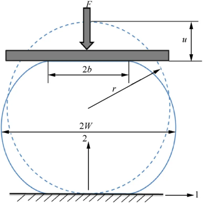
Fig.1.Schematic of single fiber transverse compression experiment[8,13].
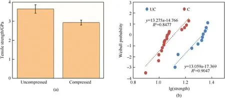
Fig.2.Single fiber HSRTC experimental results(a)Average tensile strength with 95% confidence interval(b)Weibull plot for fiber strength[13].

Fig.3.Microscope image of a compressed yarn.The red circles show regions of compression dispersed across the yarn.
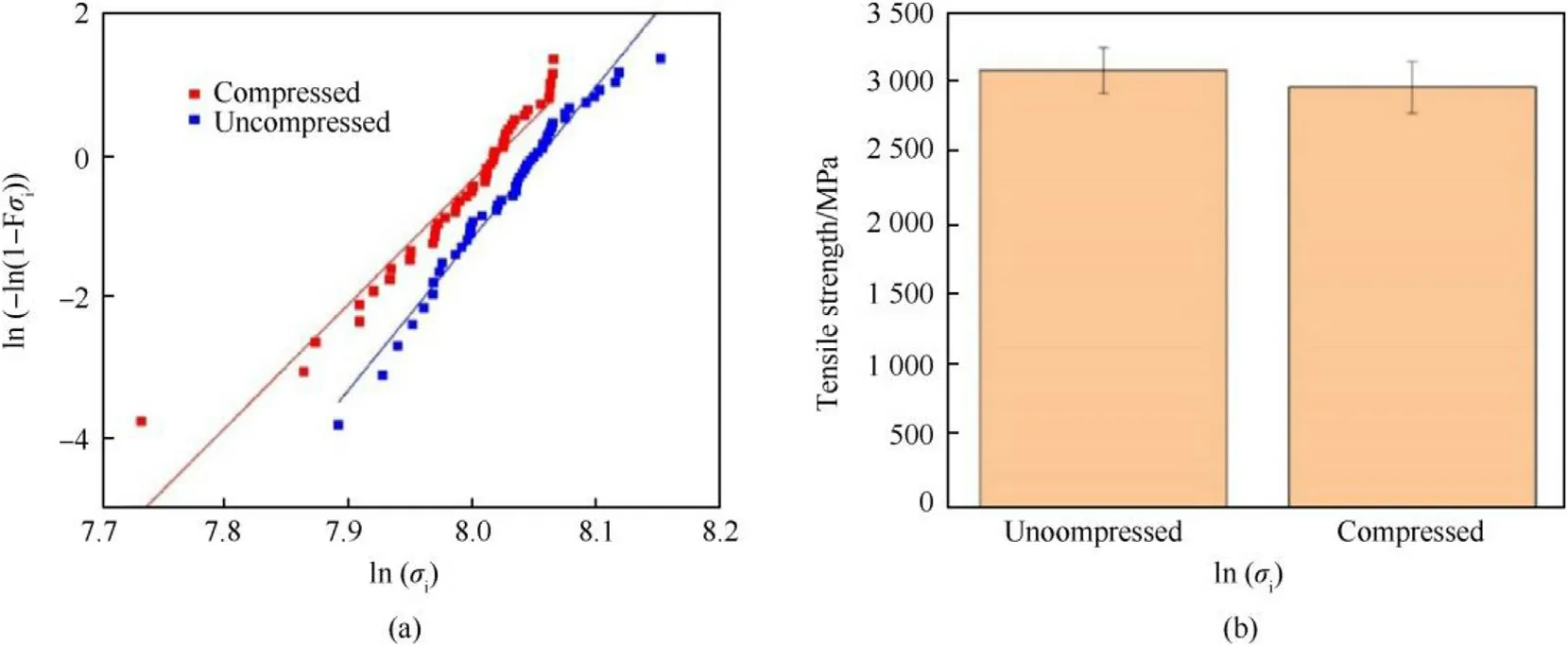
Fig.4.(a)Yarn Weibull plot,(b)Mean tensile strength of yarn samples with standard deviations.

Table 1 Weibull model parameters.
Weibull modulus is an indicator of variability in the data.A lower Weibull modulus indicates a higher variability in the modelled data quantity.For an example,the compressed sample in this study shows a lower Weibull modulus compared to the baseline(uncompressed)sample,thus indicating a wider spread in its strength.It should be noted here that the modulus of the baseline yarns found through experiments in this study is lower than the results published in the literature[2]for Dyneema®SK-75 yarns(m=31.2 at 40 twists per meter).This is likely due to the untwisted yarns tested in this work.
A comparison of the mean tensile strength between the compressed and uncompressed samples at 95% confidence interval is shown in Fig.4(b).There is only a small decrease of 3.9% in the tensile strength of compressed yarns compared to single fibers which show a 20%reduction in their tensile strength on transverse compression.Finite element modeling is required to understand this difference in behavior seen between single fibers and yarns by studying the local stress strains developed during transverse compression.Our aim is to use finite element simulations to investigate how the local strains(true strains)vary in the fibers within the yarn when it is transversely compressed to same nominal strains(u/t)as in experiments.The local or true strains of fibers are obtained directly from the commercial code LS-DYNA.LS-DYNA outputs tensorial(true)instantaneous strains and is accurate for large displacements.In the following sections,we first discuss the finite element simulation of transverse compression of single fibers,follow ed by yarns and compare the simulation results to the experimental results.
3.Single fiber transverse compression response(SFTCR)
A Dyneema®SK-76 single fiber is approximately circular[7]with an average diameter of 17.0μm and a density of 0.980 g/cm3.Ayarn of Dyneema®SK-76 is comprised of 780 such single fibers.The transverse compression response of single fibers and yarns at both quasi-static and high strain rate is studied using a 2-D plane strain FE model.The fibers are modelled using non-linear inelastic material properties presented in Table 2.These properties are derived from the experimental and modeling study by Sockalingam et al.[9]which reports a nonlinear inelastic behavior of Dyneema®SK-76 single fiber under transverse compression.All simulations are performed using the commercial FE code LS-DYNA.The following sections explain the modeling and simulation results of SFTCR and YTCR.
A previous study by Sockalingam et al.has shown that 300 finite elements are required to accurately capture the transverse compression response of Dyneema®SK-76 fiber[7].Fig.5 shows the quarter symmetric fiber model constructed using 300 2-D plane strain elements(element formulation 13 in LS-DYNA).A 2-D single surface contact is used to define the contact between the fiber and the rigid platens with a friction coefficient of 0.2.The upper platen compresses the fiber at velocity of 1.0μm/s.A nonlinear inelastic behavior is assumed for the fiber with material properties given in Table 2 and platens are assumed as rigid bodies.
After wandering about for several days until he was weary and hungry, he at last succeeded in finding a way out of the forest, and soon came to a wide and rapid river, which he followed, hoping to find some means of crossing it, and it happened that as the sun rose the next morning he saw something of a dazzling whiteness moored76 out in the middle of the stream
3.1.Single fiber quasi-static transverse compression
Fig.6 shows the simulated stress-strain response.The stressstrain response is non-linear inelastic as was observed in experiments[7].Fig.7 shows the true compressive strain contours developed in the fiber at 50%and 77%applied nominal strains.It can be observed from Fig.7 that the region near the center of the fiber develops high compressive strains and the strains reduce in magnitude away from the center.Fig.7 shows that the local true compressive strains developed in the fiber are significantly higher than the applied nominal strains of 50%and 77%.At an applied nominal strain of 77%the maximum true strain developed in the fiber is approximately 1.5 times higher,i.e.150%.These strain levels are significant enough to cause permanent deformation and fibrillation of fibers as explained in the next section.
3.2.Single fiber high strain rate transverse compression
As mentioned earlier,the transverse compression response of Dyneema®SK-76 fiber is non-linear inelastic.Sockalingam et al.in their study[9]have characterized this fiber stress-strain response into three distinct zones.
The second row in Table 2 presents the material properties applied to the fiber for high strain rate transverse compression.We consider the same finite element model as described above for HSR transverse compression of Dyneema®SK-76 single fiber with the only modification to the velocity for the upper platen.The velocity of the upper-platen is set to 1.1 m/s same as experiments.
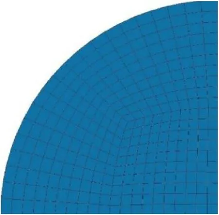
Fig.5.SFTCR quarter-symmetric FE model.
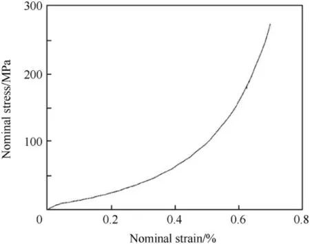
Fig.6.SFTCR predicted nominal stress nominal strain curve.
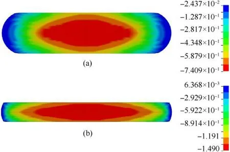
Fig.7.True compressive strain at(a)50%and(b)77%applied nominal strain from single fiber Q-S compression model.

Table 2 Non-linear inelastic properties of Dyneema®SK-76 fiber[9].
Fig.8 shows the simulated fiber nominal stress-nominal strain response.The stress-strain response is non-linear inelastic with a very small elastic limit as was also observed in experiments[9].Nominal stress for an applied nominal strain of 77%is twice as high for high strain rate compression(Fig.8)compared to quasi-static compression of single fiber.Fig.9 shows the strain distribution from the simulation at an applied nominal strain of 77%.The maximum true compressive strains developed in the fiber are approximately 1.5 times to 2 times higher than the applied nominal strain.This result is similar to the result observed for the quasistatic compression response of the fiber.Comparing Figs.9 and 7(b),we can see that the true strain distribution across the fiber is similar for both the quasi-static and high strain rate compression at 77% applied nominal strains.Dyneema®SK-76 fibers have weaker inter-fibrillar interactions compared to Kevlar fibers which possess hydrogen bonding to influence off-axis stability.At high nominal strains,fibrillation is the dominant mode of deformation in Dyneema®SK-76 fibers as reported by McDaniel et al.[7].Their results show that fibrillation begins at small loads and nominal strains in Dyneema®SK-76 fibers and leads to the breakage of fibril network into micro fibrils with significant void formation and permanent deformation.Therefore,the reduction in the tensile strength seen in experiments[13]can be attributed to fibrillation triggered by the high level of true strains developed during transverse compression.In the next section,we use SFTCR as a basis to study the transverse compression response of a yarn composed of 780 single fibers.
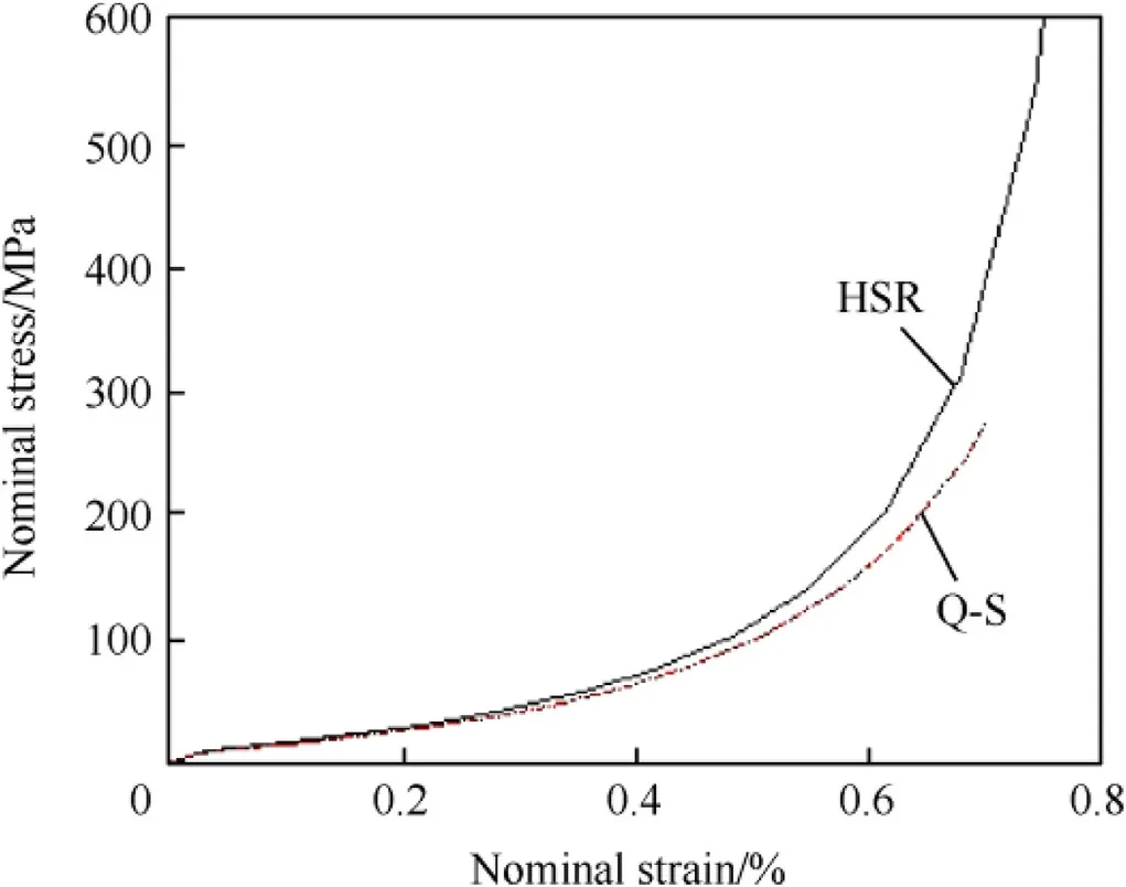
Fig.8.Single fiber HSRTC predicted nominal stress-nominal strain curve.

Fig.9.True compressive strain at applied nominal strain of 77%from single fiber HSR compression model.
4.Yarn transverse compression response(YTCR)
In this section,we model the transverse compression response of yarns to gain a better understanding of the local stress strain behavior of fibers within the yarn.
4.1.Finite element model of yarn
We consider a 2-D plane strain FE model of yarn at fiber-scale similar to the model considered by Sockalingam et al.for Kevlar KM2 fibers[17].A yarn of Dyneema®SK-76 consists of 780 single fibers.The cross-section of the yarn can be approximated as an ellipse with major and minor axis as 0.6 mm and 0.193 mm respectively.Cross-section images of Dyneema®composite laminates depict an approximately hexagonally close packing of fibers[18,19].Fig.10 shows the 2-D FE model of a yarn consisting of fibers arranged in a hexagonal closed packing.Each fiber has a circular cross-section of diameter 17.0μm and is modelled using 84 2-D plane strain elements for computational efficiency.A 2-D single surface contact with a friction coeffecient of 0.2 is defined to account for the inter-fiber interactions and the interactions between fibers and platen.The upper platen compresses the yarn at a displacement rate of 0.6 mm/min same as experiments[15].The yarn is unconstrained in the lateral direction and is free to spread.The fibers are modelled using the same non-linear inelastic material model and properties as for SFTCR.Platens are assumed as rigid body materials.
4.1.1.Yarn quasi-static transverse compression
Fig.11 shows the predicted force vs.displacement curve and nominal stress vs.nominal strain response of the yarn model compared to experiments.The experimental curve in Fig.11 represents an average of stress-strain curves produced from yarn transverse compression experiments[15].Overall,the predicted stress strain response of the yarn model is stiffer than the experimental curve.This may be due to the assumption of a hexagonally closed packed structure(maximum fiber volume fraction 0.907)for fibers in the FE model.Factors such as fiber entanglements,actual fiber packing etc.is not accounted by the FE model considered in this study.How ever,the predicted model curve and the experimental curve both show little to no increase in force until a platen displacement of 0.073 mm or 38%nominal strain.This is due to significant spreading and spatial rearrangement of the fibers as can be seen from Fig.12(a)and Fig.12(b).

Fig.10.Yarn transverse compression response FE model.
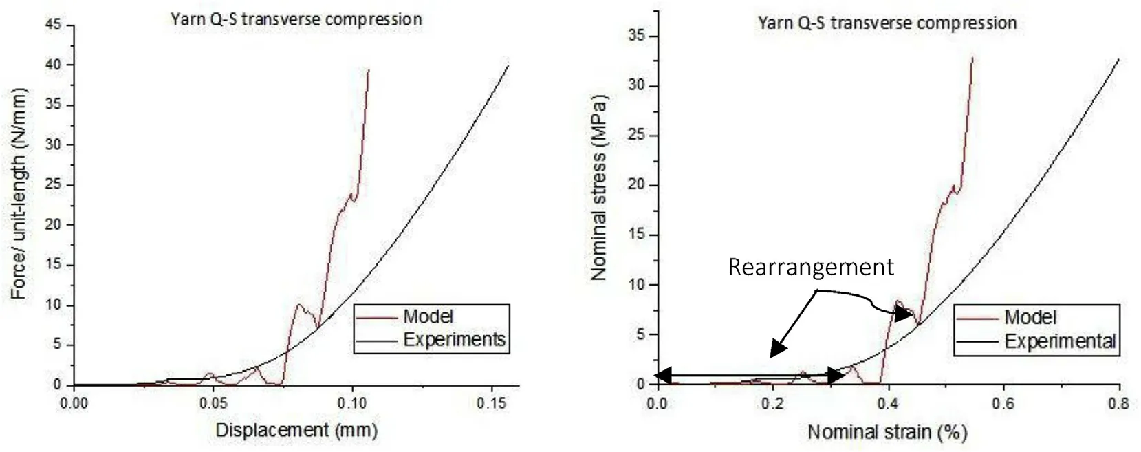
Fig.11.(a)Force versus displacement and(b)Stress versus strain comparison between predicted response from yarn model and experiments.
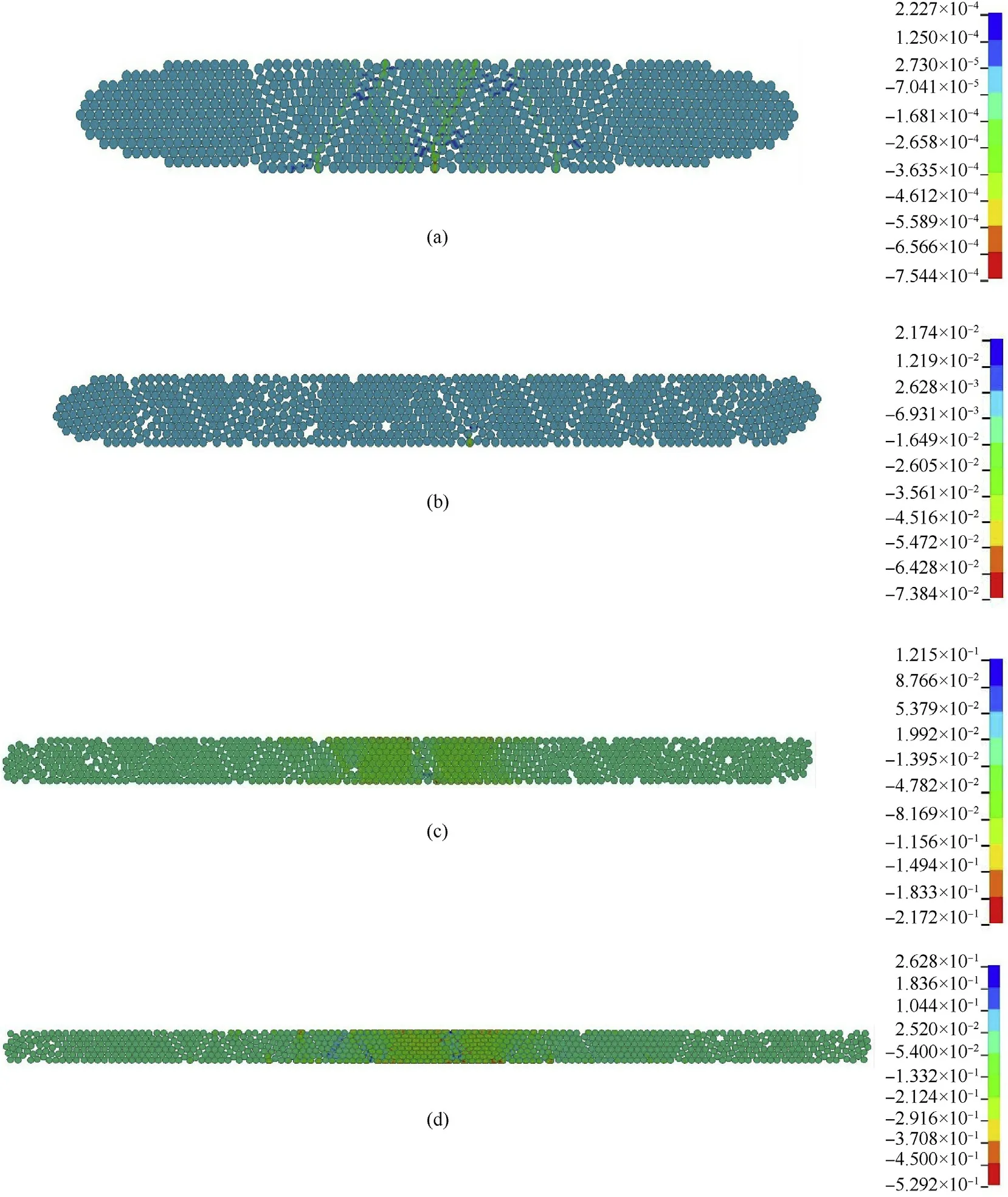
Fig.12.True compressive strain contours at(a)10%,(b)30%,(c)45%,(d)55%applied nominal strain from yarn Q-S compression model.
On further loading,both the experimental and the model curve show an increase in load or nominal stress.How ever,unlike the experimental response the predicted response exhibits another drop-in force at nominal strain of 45%.This is attributed to further spreading and rearrangement of fibers within the yarn due to a low surface friction coefficient between them.Further loading results in an increased deformation of fibers as shown by the rapid increase in force or stresses in Fig.11(b).The steeper rise in force or stress observed in the predicted response compared to the experiments after a nominal strain of 45%is due to the assumed hexagonal close packing of the fibers in the model.The actual packing and volume of fraction of fibers within the yarn is less than 90.7%as approximated by a hexagonally closed pack structure.The actual microstructure induce lower stresses for a given applied nominal strain in experiments compared to the model.
This understanding is reinforced by observing the yarn response and true compressive strains in Fig.12.At 10%applied nominal strain the fibers have displaced from their original position and show no deformation.At 55%applied nominal strains the fibers have spread significantly and have rearranged themselves within the yarn cross-section.Fibers near the center of the yarn crosssection are loaded in compression compared to fibers near the edges which show little or no deformation.It should be noted that at 55%applied nominal strain a large proportion of the fibers within the yarn show true strains only between 20%and 30%.
Transverse compression experiments on unidirectional Dyneema®laminate in the literature[18]also shows an increase in the spreading of fibers with increase in applied nominal strains.The lower reduction in the tensile strength of Dyneema®SK-76 yarns as compared to single fibers may be attributed to fiber spreading and non-uniform fiber loading during compression as seen from the simulation results in Fig.12.
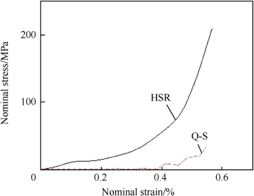
Fig.13.Yarn HSR transverse compression predicted nominal stress-nominal strain curve.
4.1.2.Yarn high strain rate transverse compression
We consider the same FE model described above for yarn HSR transverse compression with the only modification to the velocity for the upper platen as 10.0 m/s and using an explicit dynamic solver.The fibers assume non-linear inelastic behavior with high strain rate properties presented in the second row of Table 2.Platens assume elastic behavior.
Fig.13 shows the predicted nominal stress vs.nominal strain response of the yarn HSR transverse compression model.Nominal stresses are approximately six times larger for the yarn HSR compression model compared to the quasi-static model.Fig.14 shows the strain contours at approximately 55%applied nominal strain.This represents the last stable state that we were able to obtain from the model.
As observed from Fig.14 the higher strains are developed in fibers near the center of the yarn and strains within the fibers reduce going away from the center.True strains developed in fibers varies from approximately 74%-118%in the center of the yarn and reduces to applied nominal strain of 55%laterally away from the center.However,a large proportion of the fibers located away from the center and towards the yarn edges show true strains of 10%or lower compared to the applied nominal strain of 55%.Compared to the quasi-static yarn results(Fig.12),greater deformation is seen in the center of the yarn as shown by the higher strain levels in Fig.14.This may be because at high strain rates the fibers within the yarn do not have sufficient time to spread and rearrange themselves on loading.
On comparing the predicted nominal stress-nominal strain results from the single fiber model(Figs.6 and 8)and the yarn model(Figs.11 and 13)we can see that the nominal stresses developed in single fibers are approximately three times higher than those developed in yarns for an applied nominal strain of 55%.Furthermore,true compressive strains developed in single fiber(Figs.7 and 9)are significantly higher than the applied nominal strain whereas for yarns(Figs.12 and 14)a higher proportion of fibers show true strains below the applied nominal strain.The true strains observed in single fibers are high enough to cause fibrillation and permanent deformation of fibers.Fibrillation breaks down the fibril network and results in the reorientation of micro fibrils.This off-axis reorientation weakens the ability of fibril structure to carry axial loading and may likely be the reason for higher reduction in tensile strength of compressed single fibers.Transverse compression response of yarns involves significant spreading and rearrangement of fibers which is not present in the response of single fibers.The average true strains for fibers in the yarn are not significant enough to cause fibrillation of fibers within the yarn and may be the reason for a lower reduction in tensile strength of yarns as observed in experiments.How ever,it must be noted that the yarn model discussed in this study is simplistic and does not account for factors like,fiber entanglements,actual fiber packing etc.which may also contribute towards the lower tensile strength reduction observed in transverse compression experiments.It should also be noted here that yarns in a woven fabric would be constrained by the adjacent orthogonal interlacing yarns and the yarns in a composite would be constrained by the surrounding matrix resin resulting in different boundary conditions than what is considered in this study.

Fig.14.True compressive strain contours at 55%nominal strain from yarn HSR compression model.
5.Conclusions
This work presents the effect of laterally unconstrained quasistatic transverse compression on the residual tensile strength of Dyneema®SK-76 single yarns.Experimental results show that there is only a small decrease of about 4%in the tensile strength of compressed yarns at an applied average nominal strain of 77%compared to single fibers which show a 20%reduction in tensile strength.A finite element study of the transverse compression response of single fibers and yarns indicate that true strains developed in single fibers are higher than the applied nominal strain whereas a large proportion of fibers within the yarns develop true strain below the applied nominal strain.True strains developed in single fibers are 1.5-2 times higher than the applied nominal strain and are significant enough to cause fibrillation and permanent deformation of fiber.On the other hand,yarns demonstrate significant spreading and rearrangement of fibers on transverse compression.This may be the reason for the lower strains observed in yarns as compared to single fiber for the same applied nominal strain.It can also explain the lower degradation in tensile strength of yarns compared to single fibers as seen in experiments.Future areas of work is to focus on yarn high strain rate transverse compression and multi-axial loading experiments to better understand yarn failure.
Acknowledgments
Dyneema®SK-76 yarns used in this work was provided by DSM Dyneema®and is acknowledged.The useful discussions provided by Drs.Ulrich Heisserer,Harm van der Werff and Mark Hazard of DSM Dyneema®is gratefully acknowledged.The authors KSand SS acknow ledges the startup funding provided by the University of South Carolina.
- Defence Technology的其它文章
- A review of dual-spin projectile stability
- A new look on the electric spark sensitivity of nitramines
- Damage assessment of the target area of the island/reef under the attack of missile warhead
- Physical and damping properties of kenaf fibre filled natural rubber/thermoplastic polyurethane composites
- Design of infrared camouflage cloak for underground silos
- Interface defeat studies of long-rod projectile impacting on ceramic targets

