Polyurea coating for foamed concrete panel:An efficient way to resist explosion
Yi-shun Chen ,Bo Wng ,Bei Zhng ,Qing Zheng ,Jin-nn Zhou ,Feng-nin Jin ,Hu-lin Fn ,c,*
a State Key Laboratory for Disaster Prevention&Mitigation of Explosion&Impact,Army Engineering University of PLA,Nanjing 210007,China
b Research Center of Lightweight Structures and Intelligent Manufacturing,State Key Laboratory of Mechanics and Control of Mechanical Structures,Nanjing University of Aeronautics and Astronautics,Nanjing 210016,China
c State Key Laboratory of Disaster Reduction in Civil Engineering,Tongji University,Shanghai 200092,China
Keywords:Autoclaved aerated concrete Polyurea Explosion Failure
ABSTRACT Autoclaved aerated concrete(AAC)panels have ultra-light weight,excellent thermal insulation and energy absorption,so it is an ideal building material for protective structures.To improve the blast resistance of the AAC panels,three schemes are applied to strengthen the AAC panels through spraying 4 mm thick polyurea coating from top,bottom and double-sides.In three-point bending tests,the polyurea-coated AAC panels have much higher ultimate loads than the un-coated panels,but slightly lower than those strengthened by the carbon fiber reinforced plastics(CFRPs).Close-in explosion experiments reveal the dynamic strengthening effect of the polyurea coating.Critical scaled distances of the strengthened AAC panels are acquired,which are valuable for the engineering application of the AAC panels in the extreme loading conditions.Polyurea coatings efficiently enhance the blast resistance of the bottom and double-sided polyurea-coated AAC panels.It is interesting that the polyurea-coated AAC panels have much more excellent blast resistance than the CFRP reinforced AAC panels,although the latter have better static mechanical properties.©2020 China Ordnance Society.Production and hosting by Elsevier B.V.on behalf of KeAi Communications Co.This is an open access article under the CCBY-NC-ND license(http://creativecommons.org/licenses/by-nc-nd/4.0/).
1.Introduction
Nowadays,blast resistant ability of constructions has been widely concerned due to growing terrorist attacks.Autoclaved aerated concrete(AAC)is a kind of lightweight,multi-functional and environment-friendly building material[1-3].How ever,AAC panels usually have low impact or blast resistance and must be strengthened under explosion[4,5].Fiber reinforced plastics(FRPs)have been used to strengthen the AAC panels[6-10],which can also reduce secondary injury through restricting spalling and fragments produced by the explosion.Wang et al.[11]applied carbon fiber reinforced plastics(CFRPs)to retro fit the AAC panels.
Polyurea is a new type of elastic polymer.Compared with the CFRP,it has advantages of high construction efficiency,firm cohesiveness with concrete and good environmental adaptability.Researchers found that the polyurea also displayed excellent protective performance in impact and explosion.Parniani and Toutanji[12]investigated fatigue performance of RC beams retrofitted by polyurea coating.Toutanji et al.[13]applied polyurea coating to high-performance organic cementitious materials.Through experiments,Ha et al.[14]studied strengthening effect of hybrid CFRP-PU on RC panels under blast loading.
Spraying polyurea material on aerated concrete block wall can effectively improve the anti-explosion performance[15].Under explosion,the polyurea layer can reduce the structural flexure,and turn the global collapse of unreinforced wall into local damage and cracks in the walls.How ever,increasing the thickness of the polyurea coating does not seem to contribute significantly to further reduction of the displacement when compared to the thinner coating[16].It is also noticed that a polyurea coating on the nonblast-facing face tends to be more effective in terms of displacement control[16].
In this paper,the AAC panels were strengthened by polyurea coatings,and the dynamic strengthening effects were investigated by close-in explosion tests and compared with those of the CFRP strengthened panels.
The AAC panels used in this research are produced by Nanjing Asahi New Building Materials Co.,Ltd.,with density of 525 kg/m3.The cellular structure,with pore diameter smaller than 1 mm,is shown in Fig.1(a).The AAC is brittle and its physical and mechanical properties are listed in Table 1.The polyurea has quite large deformation and its modulus increases with the strain,as shown in Fig.1(b).Combination of these two materials could create structures with excellent energy absorption.
In this research, each AAC panel is 1200 mm×600 mm×100 mm,with weight of about 50 kg.These panels are reinforced by double-layer steel rebars,and each layer contains 9 steel rebars with diameter of 5 mm,as shown in Fig.2.The physical and mechanical properties of the polyurea are listed in Table 2.
The polyurea is sprayed onto the surface of the foamed concrete panel layer by layer.The spraying thickness of each layer is about 0.3 mm.After spraying one layer,the sprayed mass of the polyurea can be read from the machine.The polyurea coating for the foamed concrete panels is 4 mm thick,which will be controlled from the total mass of the sprayed polyurea.
In this research,three kinds of polyurea-coated AACpanels are designed:(a)top coating,(b)bottom coating and(c)double-sided coating,as shown in Fig.3.CFRP strengthened AAC panels are also tested for comparison,as shown in Fig.4.
2.Quasi-static three-point bending testing
Quasi-static three-point bending test is carried out on MTS(material testing system)machine at a loading rate of 1.2 mm/min,with span of 1000 mm.The load-displacement curves and failure modes of the un-strengthened,the CFRP strengthened and the bottom polyurea-coated AAC panels are as shown in Fig.5.
Through the flexure curve,the flexural rigidity,B,of the panel can be calculated by

where F,δ,and l denote the applied force,the mid-span flexure and the span,respectively.For the three panels,the flexural rigidities are 55 k N·m2,109 k N·m2and 96 k N·m2,respectively.It is clear that the strengthened AAC panels have much greater rigidity.As the CFRP is stiffer than the polyurea coating,the CFRP strengthened panel has the greatest rigidity.The peak loads of the three panels are 10.65 k N,19.32 k N and 16.78 k N,respectively.Therefore,both the CFRP and the polyurea coating can enhance the load capacity of the AAC panels,but the improvement from the CFRP is a little better.For the un-strengthened AAC panel,the crack appears suddenly in the shear zone,extends obliquely and penetrates the panel from the support to the mid-span,leading to brittle shear failure.The CFRP strengthened and the bottom polyurea-coated AAC panels fail suddenly due to bending-shearing crack,which initiates at the lower surface and then extends diagonally across the mid-span cross section.
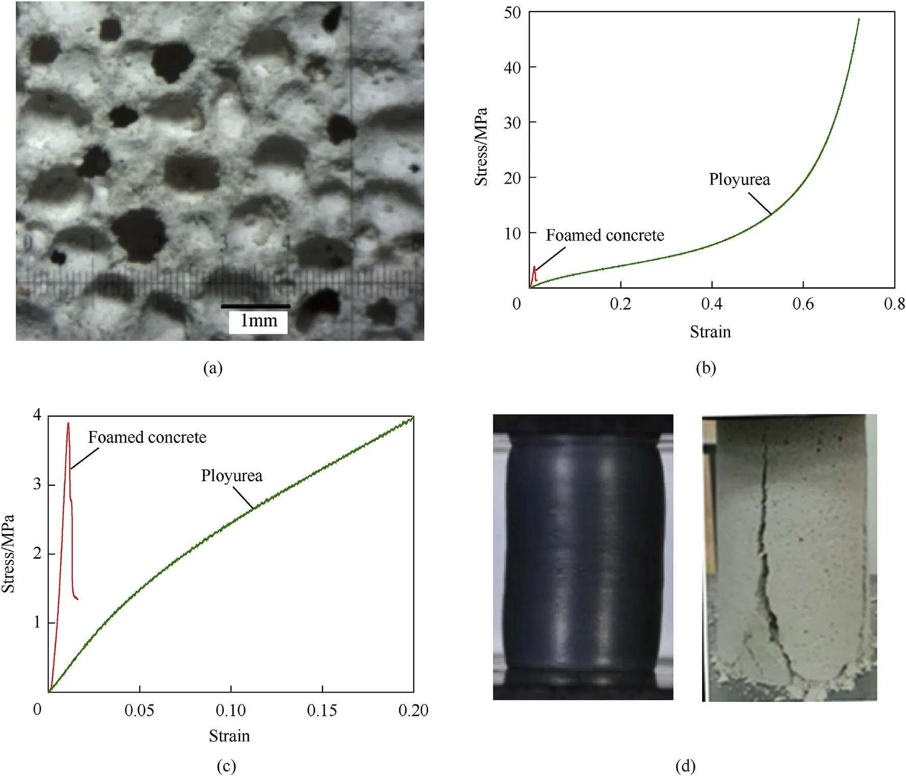
Fig.1.Structure and mechanical properties of AAC:(a)cellular structure,(b)complete and(c)initial compression curves and(d)failure mode compared with polyurea.

Table 1 Physical and mechanical properties of AAC.
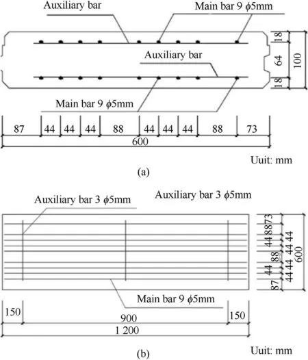
Fig.2.Reinforcements of the AAC panels:(a)cross section and(b)top view[11].
3.Blast responses of AAC panels
3.1.Experimental schemes
Seven explosion experiments are performed to investigate the dynamic properties of the polyurea-coated AAC panels under various scaled distances,as listed in Table 3.As shown in Fig.6,the panel is placed on a steel frame with dimensions of 1150 mm×1100 mm×500 mm and constrained by steel rollers.The span of the panel is 1000 mm.The charge is suspended above the central of the panel with standoff distance of 0.8 m with mass varying from 0.1 kg to 0.3 kg.The corresponding scaled distance ranges from 1.195 m/kg1/3to 1.723 m/kg1/3.The reflected wave pressure on the plate surface is measured by the pressure sensor at the mid-span and 1/4 of the width away from the side.The free field pressure is measured by the PCB free field pressure sensor,which is 3 m away from the charge horizontally.The mid-span flexure is measured by a Linear Variable Displacement Transducer(LVDT),whose maximum range is 100 mm with 10 k Hz sampling rate.The strain of the polyurea coating is measured by three strain gauges at the bottom of the panel,w hose maximum range is 10000με.
3.2.Pressure analysis
The pressure curves measured by the PCB free field pressure sensor and the pressure sensor on the AAC panel with scaled distances of 1.723 m/kg1/3,1.368 m/kg1/3and 1.195 m/kg1/3are displayed in Fig.7.
To compare the difference between the experimental and calculated values[17],the experimental error is evaluated and listed in Table 4,where Piand Prrepresent the peak pressures of the free field and the reflection,and can be calculated by Ref.[17].

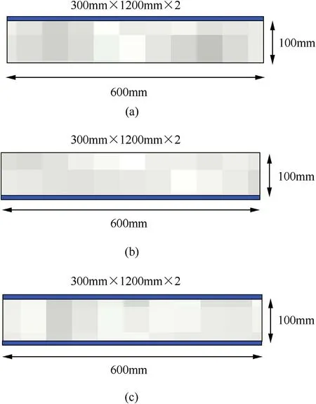
Fig.3.Schematic diagrams for the polyurea strengthened methods of(a)top coating,(b)bottom coating and(c)double-sided coating.
where C is the weight of TNT,h is the distance from the measure point to the TNT.
The reflected peak pressure Pr,is determined by

where the reflective coefficient,r,can be determined by the incident peak pressure Piand the incident angle α through Fig.8.The experimental errors of Pimeasured by PCB are relatively small.The errors of the reflected pressures measured by the pressure sensors on the surface of the panel are also acceptable.Information about the measured pressures is limited.As the calculation is consistent with the experiment,the detailed distribution of the reflected pressure can be calculated by Eq.(1)and Eq.(2).
3.3.Blast-resistant ability
Three explosion experiments with scaled distances of 1.723 m/kg1/3,1.368 m/kg1/3and 1.195 m/kg1/3are carried out on the bottom polyurea-coated AAC panels(B-1,B-2 and B-3)respectively,as shown in Fig.9.
There is no damage found in B-1 after explosion,as shown in Fig.9(a),and its permanent deflection is zero,which means the panel has no plastic deformation during explosion.For B-2 panel,small cracks appear on its upper surface,with directions parallel to the long side of the panel,as shown in Fig.9(b).Seen from displacement-time curve,B-2 has no permanent deformation either,indicating that the explosion causes no destructive damage to the panel,and the polyurea on the lower surface plays an important role in strengthening.The damage of B-3 in explosion has showed obvious characteristics of bending-shear failure,with transverse cracks perpendicular to the long side on the upper surface,as shown in Fig.9(c).From the flexure curve,the permanent deflection is 2.71 mm,which means that B-3 has been severely damaged.How ever,scattered fragments are hardly seen after destruction,indicating that bottom polyurea coating can effectively control the splashing of the fragments.
Tw o explosions with scaled distances of 1.368 m/kg1/3and 1.195 m/kg1/3are conducted on the double-sided polyurea-coated AAC panels(D-1 and D-2),as shown in Fig.10.There was no damage found in D-1 after explosion.Bending-shearing coupling failure occurs in D-2.No cracks are observed on the upper and lower surfaces of D-2,but there are some slanting cracks on the side.The flexure curve shows that it produces permanent deflection of 5.28 mm and overall destruction has occurred.
Two explosions with scaled distances of 1.723 m/kg1/3and 1.368 m/kg1/3are performed on the top-polyurea-coated AAC panels(T-1 and T-2),as shown in Fig.11.No cracks are observed on the surface of T-1,but its permanent deflection is 1.03 mm,indicating the panel has been damaged inside.A slanting crack appears on the side of T-2 with obvious characteristics of bending-shearing coupling failure.With much more severe damage than T-1,T-2 has a permanent deflection of 4.32 mm.
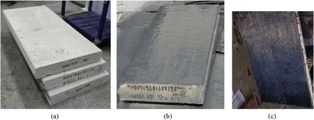
Fig.4.(a)Un-coated,(b)polyurea-coated,and(c)CFRPstrengthened AAC panels.
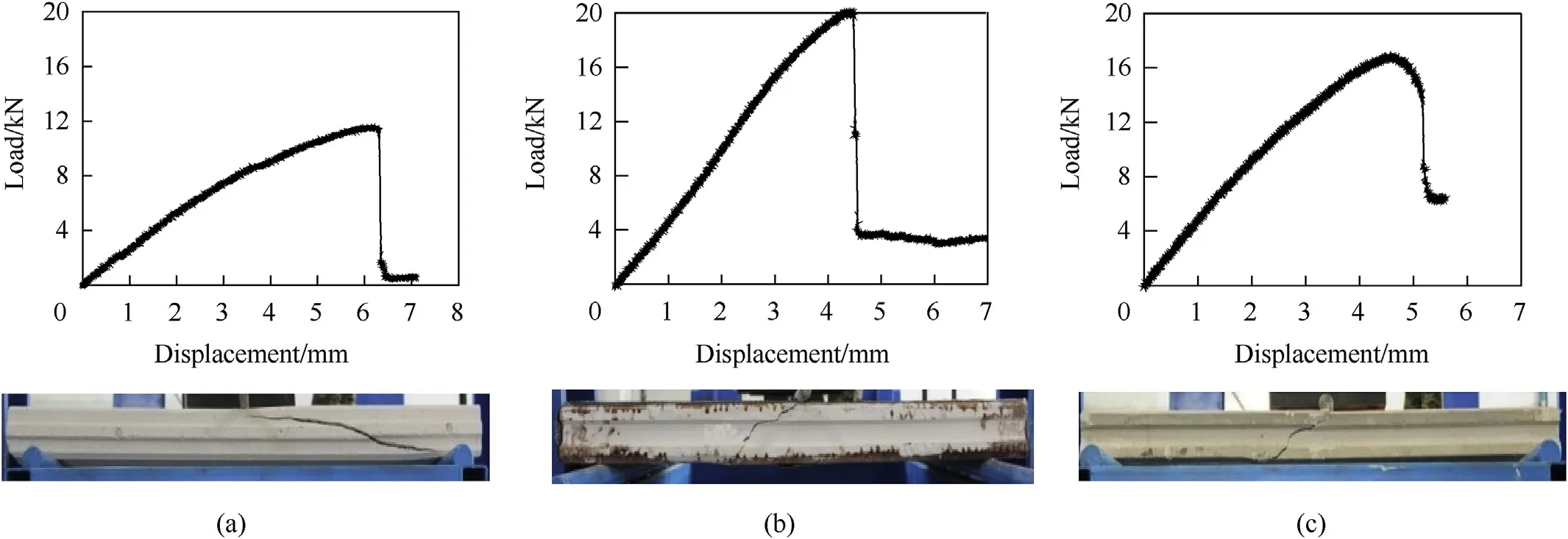
Fig.5.Failure modes and load-displacement curves of(a)un-strengthened AAC panel,(b)unidirectional CFRP strengthened AAC panel[11]and(c)bottom polyurea-coated AAC panel.

Table 3 Explosion schemes.
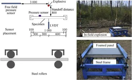
Fig.6.Explosion experiment setup(Unit:mm).
Failure styles of the bottom,the double-sided and the top polyurea-coated and the CFRP reinforced AAC panels[11]with scaled distance of 1.368 m/kg1/3are compared,as shown in Fig.9(b),10(a),11(b)and Fig.12.It can be seen that the damage degree of the polyurea-coated AAC panels is much smaller,and that of the CFRP reinforced AAC panels[11]under scaled distance of 1.368 m/kg1/3is comparable to that of the double-sided polyureacoated AAC panel under scaled distance of 1.195 m/kg1/3.
3.4.Deflection analysis
Table 5 and Table 6 list the maximum deflection and permanent deflection of the panels.In general,with the decrease of the scaled distance,the maximum deflection of the polyurea-coated AAC panels increases.The magnitude of the permanent deflection indicates the damage degree of the panels.

Table 4 Pressure error analysis.
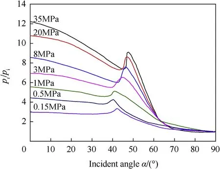
Fig.8.The reflective coefficient[17].
Figs.9(a)and Fig.10(a)show the response curves of the undamaged panels,w hose permanent deflections are zero.The curves include narrow troughs and wide peaks,caused by the forced downward vibration of the shock wave and the free vibration of the panel,respectively.For undamaged panels,the amplitudes of the wave peak and trough have little differences.Fig.9(c)and Fig.10(b)show the response curves of the damaged panels.They have much greater maximum and permanent deflections.The amplitude of the wave peak is obviously smaller than that of the trough for the seriously damaged panels.These panels have irreversible permanent deflections.
3.5.Strain analysis
The charge is suspended above the central of the panel.The strains are larger at the mid-span and smaller on the sides,and increase with decrease of the scaled distance.Fig.13 shows the strain gauge positions and strain-time curves of B-1,which is undamaged in explosion.All these curves have a sharp wave and decay rapidly out of the blast duration.The maximum strain at the central point is larger than 0.01 and finally decays to zero,indicating that there is almost no residual and plastic deformation.
4.Structural damage evaluations
4.1.Damage evaluation method
To evaluate the damage of the panel,a structural damage factor,D is defined by Ref.[11].

where PIand PDare the ultimate loads of the panel before and after explosion.The structural damage factor can also be defined by

where BIand BDare the bending rigidities of the panel before and after explosion.
4.2.Residual flexural performance and damage evaluation
The undamaged bottom polyurea-coated AAC panel under 1.368 m/kg1/3is bended to obtain its residual load capacity.Wang et al.[11]revealed the load capacities of un-strengthened AAC panels and CFRP strengthened AAC panels before and after explosion.The test results of bottom polyurea-coated AAC panels are compared with them.Fig.14 shows the flexural curves and failure modes of un-strengthened,CFRP strengthened and bottom polyurea-coated AAC panels after explosion.The structural damage is evaluated by Eq.(3)and listed in Table 7.The original load capacity of the bottom polyurea-coated AAC panel is 16.78 k N,higher than that of the un-strengthened AAC panel,10.65 k N,but lower than that of the unidirectional CFRP strengthened AAC panel,19.32 k N.How ever,the residual load capacity of the bottom polyurea-coated AAC panel is the highest.Therefore,the structural damage factor of the bottom polyurea-coated AAC panel is smaller than that of the CFRP strengthened AACpanel,indicating that the former has better blast-resistant ability.
According to the flexural curves,the residual bending rigidity of the CFRP strengthened panel is 38.8 k N·m2,while that of the polyurea-coated AAC panel is 72.1 k N·m2.The exploded panels become much more flexible.The structural damage can also be evaluated by Eq.(4),as listed in Table 8.The structural damage factor of the bottom polyurea-coated panel is much smaller than that of the CFRP strengthened panel even from the perspective of deformation,indicating that the polyurea-coated panel has better blastresistance.This result is consistent with the residual load capacity.
4.3.Critical scaled distance
According to seven groups of explosion experiments,critical scaled distances of polyurea-coated AAC panels with different strengthened methods are listed in Table 9.
When the scaled distance is less than the critical value,the AAC panel will produce serious damage after the explosion;otherwise,the AAC panel will continue to work safely after the explosion.Therefore,its critical value has great importance in engineering applications of AAC panel under extreme loading conditions.The critical scaled distance of un-strengthened AAC panes is 1.723-1.506 m/kg1/3,while that of CFRP strengthened AAC panel[11]is reduced to 1.506-1.368 m/kg1/3,indicating an improvement in blast resistance.The critical scaled distance of top polyureacoated AAC panels is 1.723-1.368 m/kg1/3.Compared with AAC panels,top polyurea coating enhances the blast ability of AAC panels,but the strengthening effect is not ideal.Bottom polyureacoated and double-sided polyurea-coated AAC panels have the same scaled distance of 1.368-1.195 m/kg1/3,even much smaller than that of CFRP strengthen AAC panels,indicating that bottom polyurea coating and double-sided polyurea coating are more efficient in strengthening than CFRP strengthening technique and can bear more intense blast loading,as shown in Fig.15.
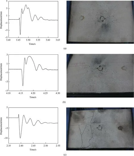
Fig.9.Failure styles and flexure curves of AAC panels:(a)B-1,(b)B-2 and(c)B-3.
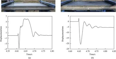
Fig.10.Failure styles and flexure curves of AAC panels:(a)D-1,(b)D-2.
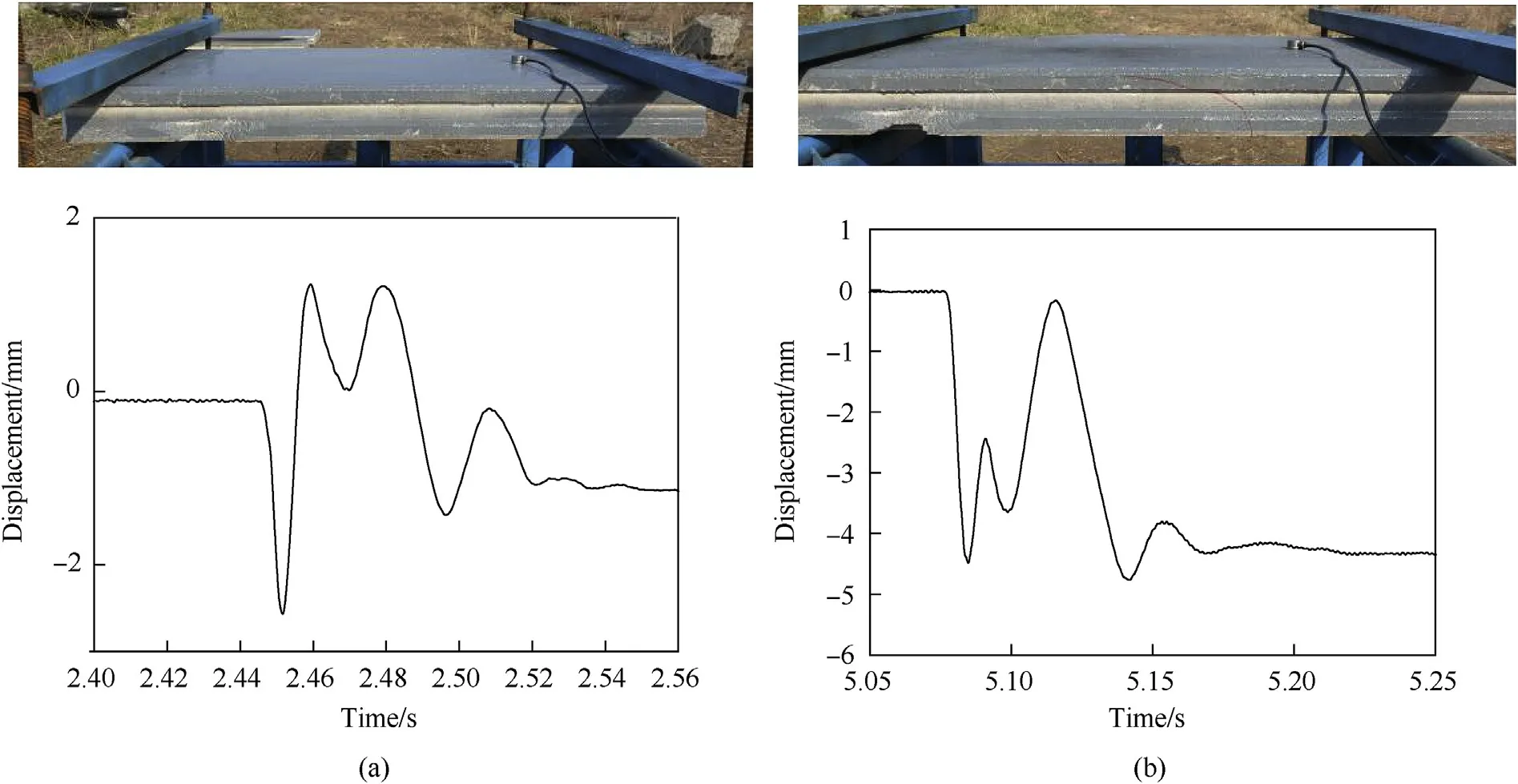
Fig.11.Failure styles and flexure curves of AAC panels:(a)T-1,(b)T-2.
5.Discussions
Restricted by the low strength of the AAC,strength of the strengthening material CFRP cannot be fully utilized,and the panel will fail at AAC shear or tensile failure,or debonding.Therefore,polyurea coated AAC panels have better dynamic performance than CFRP strengthened AAC panels.The advantages of polyurea in dynamic strengthening can be explained in the following aspects.
Firstly,the adhesive strength between the polyurea and the AAC is much stronger.Debonding occurs in blast-loaded CFRP strengthened AAC panels,reducing its strengthening effect.However,in polyurea coated AAC panels,the debonding is not observed and cracks usually form and develop in the AAC.

Fig.12.Failure style of CFRP reinforced AAC panel[11]under explosion with scaled distance of 1.368 m/kg1/3.
Secondly,the equivalent static load,Ps,is always applied toevaluate the blast resistance of beams.

Table 5 Displacements of polyurea-coated AAC panels.

Table 6 Displacements of CFRP strengthened AAC panels[11].
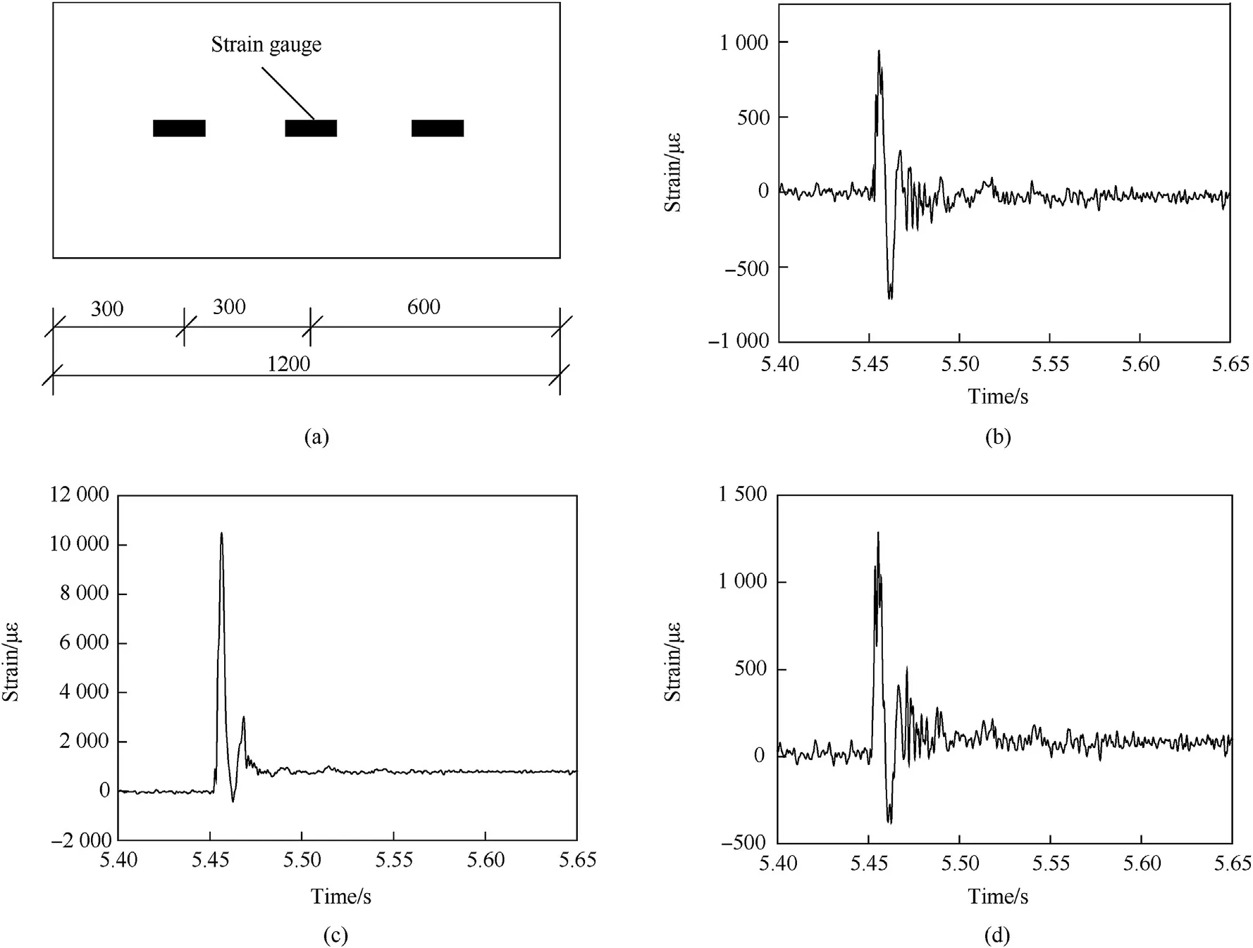
Fig.13.Strain gauges position(a)and strain-time curves of(b)left strain,(c)middle strain and(d)right strain.
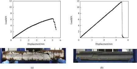
Fig.14.Quasi-static flexural curves and failure modes of(a)CFRP strengthened AAC panel UCRAP-2[11]and(b)bottom polyurea-coated AAC panel B-2 after explosion.

Table 7 Structural damage evaluation through residual load capacity.

Table 8 Structural damage evaluation through residual bending rigidity.

Table 9 Critical scaled distances of AAC panels with different strengthened methods.

where Pmis the uniform peak pressure,P0is the maximum peak pressure of the shock wave,κ is a distribution factor of blast wave,and k is the dynamic coefficient.For ordinary chemistry explosion,the shock duration,T,is usually within 1 ms.The pressure contour on the panel is shown in Fig.16,where the peak pressure is calculated by CONWEP.The distribution factor is also suggested in Table 10.
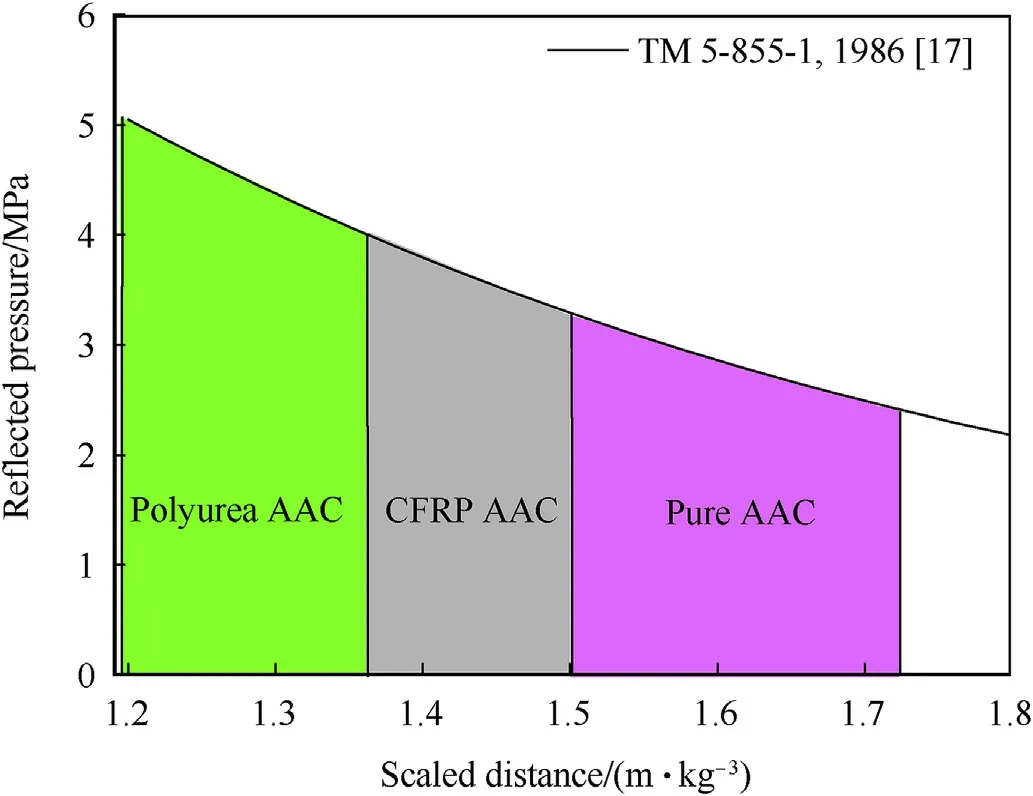
Fig.15.Peak pressure sustained by AAC panels with different strengthening scheme.
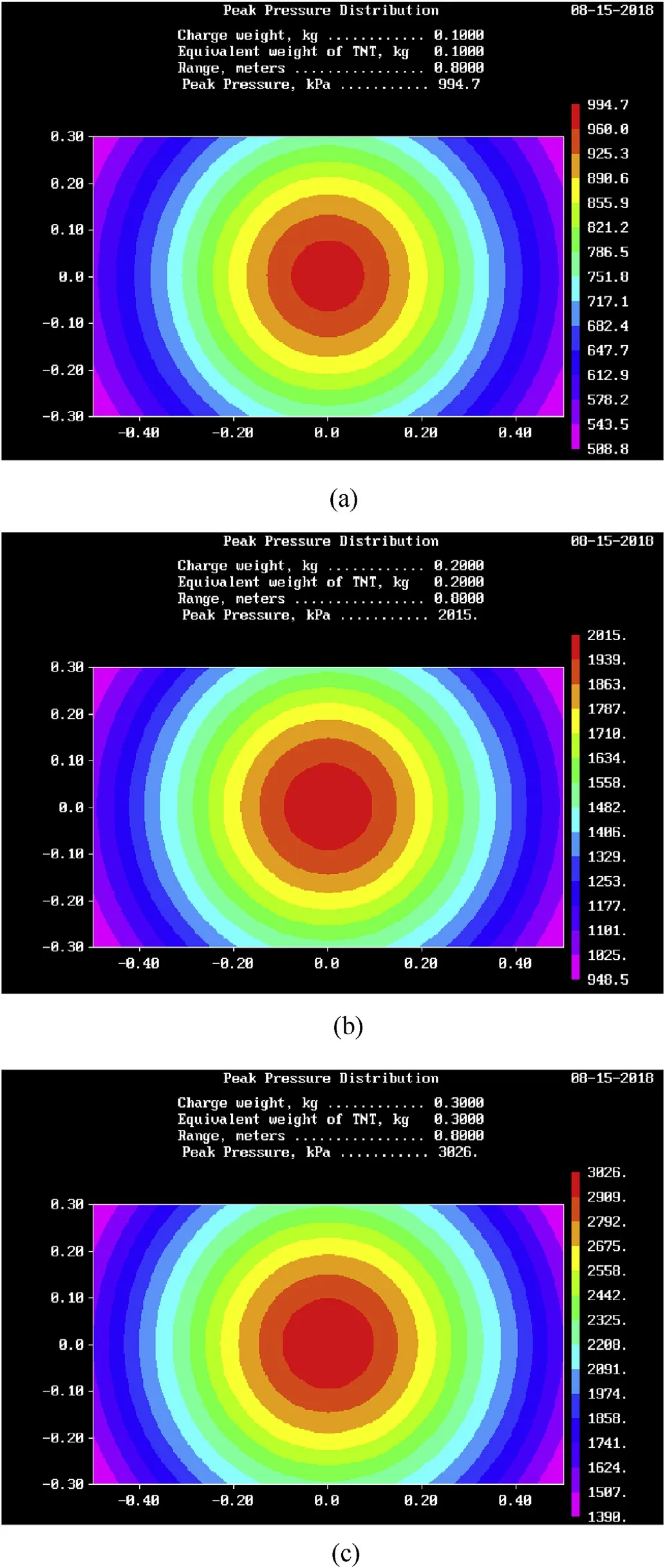
Fig.16.Peak reflective pressures on the front surface of the panel under explosion with scaled distance of(a)1.723 m/kg1/3,(b)1.368 m/kg1/3 and(c)1.195 m/kg1/3.

Table 10 Constants of blast wave calculated by CONWEP.
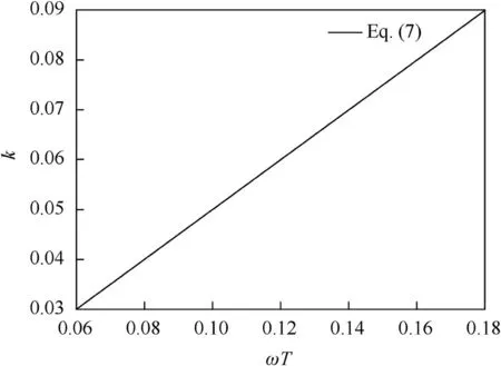
Fig.17.Dynamic coefficient varying with ω T.
The dynamic coefficient is related to ω T as

where T is the blast wave duration,and ω is the fundamental frequency of the structure and given by Ref.[17].

where l is the span,m is the mass per unit length,B is the bending rigidity and Ω=9.87 for simply-supported beam.As shown in Fig.17,when ωT is large enough,the dynamic load acts as quasistatic load and the dynamic coefficient tends to 1.0.When ωT is small,the dynamic load acts as a pulse and the dynamic coefficient is very small,even smaller than 0.1.
The flexural rigidities of the three panels are different,inducing different ω.Smaller k is acquired from smaller ω T according to Eq.(7).The dynamic coefficient is smaller than 0.1,as listed in Table 11 and compared in Fig.18(a).With smaller elastic modulus than the AAC,polyurea coating has little influence to the flexural rigidity of the AAC panel,while CFRP layer can obviously enhance the rigidity,thus improving the fundamental frequency of the panel and leading to much larger dynamic coefficient k.Therefore,although the equivalent static load-bearing capacity of the CFRP strengthenedAAC panel is much better,as shown in Fig.18(b),its anti-blast ability is poorer than that of the polyurea-coated panel,w hose dynamic coefficient is much smaller.
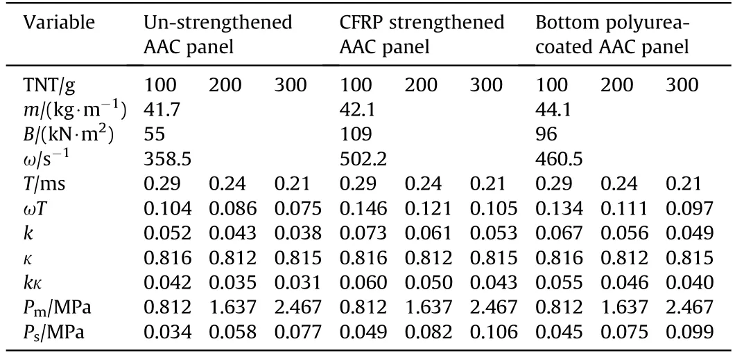
Table 11 Dynamic coefficients and equivalent static loads.
The mid-span deflection of the blast-loaded panels can be predicted by

where b is the width of the panel.The predictions are compared with the tested data in Fig.18(c).The tested deflection of the polyurea-coated panel under scaled distance of 1.368 m/kg1/3,3.91 mm,has great difference with the theoretical prediction,which is most likely caused by measurement mistakes.Other errors of the predictions for the polyurea-coated panels are acceptable.The prediction results are a little smaller,which may be induced by the underestimated bending rigidity got from the flexure curves.
6.Conclusions
By analyzing the results of close-in explosion experiments and quasi-static three-point bending tests,the following conclusions can be reached:
1)The polyurea coating efficiently enhances the mechanical properties of the AAC panels.The original load capacity of the bottom polyurea-coated AAC panel is higher than that of the unstrengthened AAC panel,but lower than that of the unidirectional CFRP strengthened AAC panel.
2)The blast-resistant ability of the top polyurea-coated AAC panel is not obviously enhanced,weaker than the bottom and doubleside polyurea-coated AAC panels.
3)Compared with the bottom polyurea-coated AAC panel,the blast-resistant ability of the double-side polyurea-coated AAC panel is not enhanced obviously.Therefore,the blast-resistant ability of the polyurea-coated AAC panel mainly depends on the bottom coating.
4)Critical scaled distances of the polyurea-coated AAC panels with different strengthened methods have been acquired.These data are of great importance for promoting engineering applications of the AAC panel in extreme loading conditions.
5)From the perspective of structural damage factors and critical scaled distances,the blast-resistant ability of the bottom and double-sided polyurea-coated AAC panels are stronger than that of the CFRP strengthened AAC panel.Excellent adhesion and ductility make polyurea coating an alternative to existed strengthening techniques in protective structures against explosion.
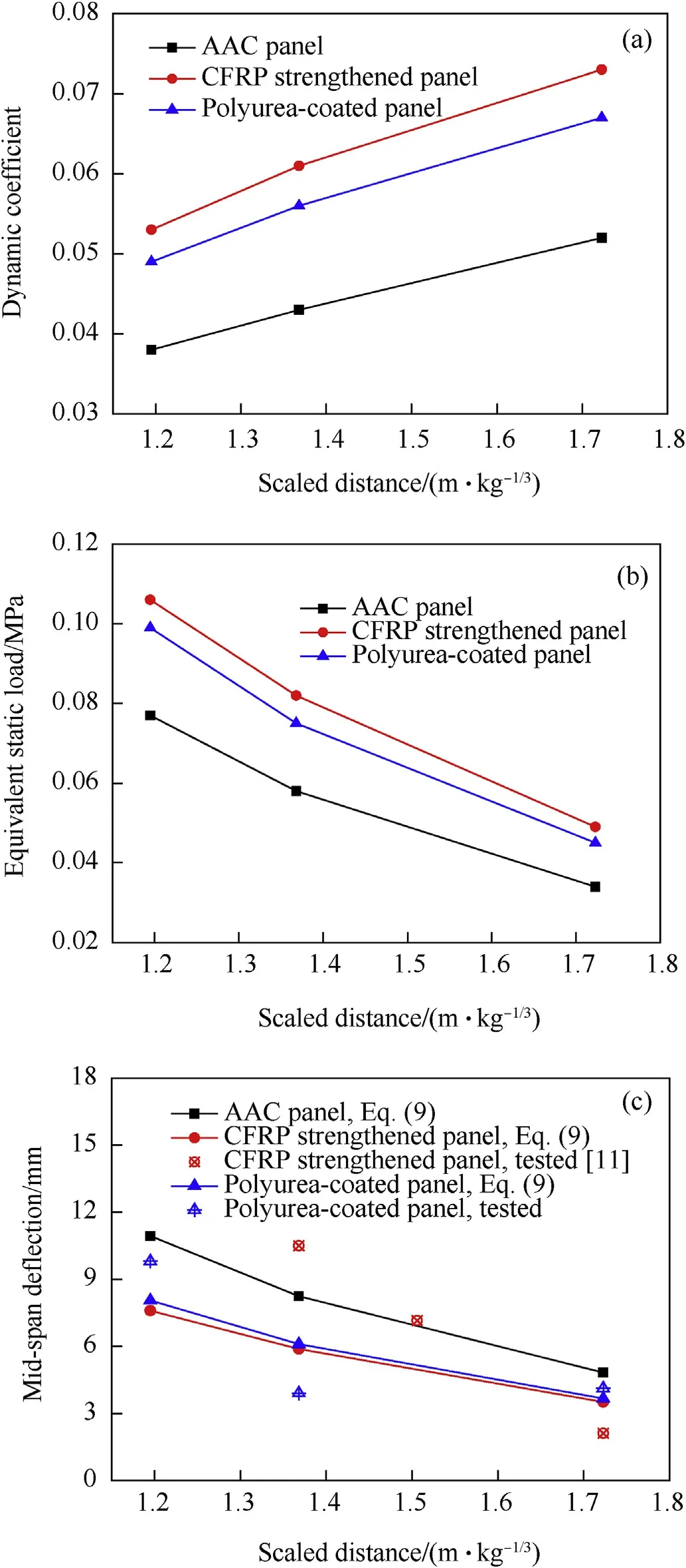
Fig.18.(a)Dynamic coefficients and(b)equivalent static loads of AAC panels and(c)predicted mid-span deflections by equivalent static load method.
Acknowledgments
Supports from the National Natural Science Foundation of China(11672130,51508567,51478465,and 51308544),the State Key Laboratory of Mechanics and Control of Mechanical Structures(MCMS-0217G03)and the State Key Laboratory for Disaster Reduction in Civil Engineering(SLDRCE16-01)are gratefully acknowledged.
- Defence Technology的其它文章
- A review of dual-spin projectile stability
- A new look on the electric spark sensitivity of nitramines
- Damage assessment of the target area of the island/reef under the attack of missile warhead
- Physical and damping properties of kenaf fibre filled natural rubber/thermoplastic polyurethane composites
- Effect of transverse compression on the residual tensile strength of ultrahigh molecular weight polyethylene(Dyneema®SK-76)yarns
- Design of infrared camouflage cloak for underground silos

