New Precursors Derived Activated Carbon and Graphene for Aqueous Supercapacitors with Unequal Electrode Capacitances
Yao Chen , George Zheng Chen
1 The State Key Laboratory of Refractories and Metallurgy, College of Materials and Metallurgy, Wuhan University of Science and Technology, Wuhan 430081, P. R. China.
2 Department of Chemical and Environmental Engineering, Faculty of Science and Engineering, University of Nottingham Ningbo China, Ningbo 315100, Zhejiang Province, P. R. China.
3 Department of Chemical and Environmental Engineering, Faculty of Engineering, University of Nottingham, Nottingham NG2 7RD, UK.
Abstract: Carbon materials can offer various micro- and nanostructures as well as bulk and surface functionalities; hence,they remain the most popular for manufacturing supercapacitors.This article critically reviews recent developments in the preparation of carbon materials from new precursors for supercapacitors. Typical examples are activated carbon (AC) and graphene, which can be prepared from various conventional and new precursors such as biomass, polymers, graphite oxide, CH4, and even CO2 via innovative processes to achieve low-cost and/or high specific capacitance. Specifically, when producing AC from natural biomasses or synthetic polymers, either new, spent, or waste,popular activation agents, such as KOH and ZnCl2, are often used to process the ACs derived from these new precursors while the respective activation mechanisms always attract interest. The traditional two-step calcination process at high temperatures is widely employed to achieve high performance, with or without retaining the morphology of the precursors.The three-step calcination, including a post-vacuum treatment, is also the preferred choice in many cases, but it can increase the cost per capacity (kWh·g-1). More recently, one-step molecular activation promises a better and more economical approach to the commercial application of AC, although further increase of the yield is necessary. In addition to activation, graphitization, N doping, and template control can further improve ACs in terms of the charging and discharging rates, or pseudocapacitance, or both. Considerations are also given to material structure design, and carbon regeneration during activation. Metal-organic frameworks, which were initially used as templates, have been found to be good direct carbon precursors. Various graphene structures, including powders, films, aerogels, foams, and fibers, can be produced from graphite oxide, CO2, and CH4. Similar to AC, graphene can possess micropores by activation. Selfpropagating high-temperature synthesis and molten salt processing are newly-reported methods for fabrication of mesoporous graphene. Macroporous graphene hydrogels can be produced by hydrothermal treatment of graphite oxide suspension, which can also be transferred into films. Hierarchically porous structures can be achieved by H2O2 etching or ZnCl2 activation of the macroporous graphene precursor. Sponges as templates combined with KOH activation are applied to create both micro- and macropores in graphene foams. Graphene can grow on fibers and textiles by electrodeposition,dip-coating, or filtration, which can be woven into clothes with a large area or thick loading, illuminating the potential application in flexible and wearable supercapacitors. The key obstacles in AC and graphene production are high cost, low yield, low packing density, and low working potential range. Most Carbon materials derived from new precursors work very well with aqueous electrolytes. Charge storage occurs not only in the electric double layer (i.e., the “carbon | electrolyte”interface), but also via redox activity in association with the bulk and surface functionalities, and the resulting partial delocalization of valence electrons. The analysis of the capacitive electrode has shown a design defect that prevents the working voltage of a symmetrical supercapacitor from reaching the full potential window of the carbon material. This defect can be avoided in AC-based supercapacitors with unequal electrode capacitances, leading to higher cell voltages and hence higher specific energy than their symmetrical counterparts. There are also emerging ways to raise the energy capacity of AC supercapacitors, such as the use of redox electrolytes to enable the Nernstian charge storage mechanism,and of the three dimensional printing method for a desirable electrode structure. All these developments are promising carbon materials from various precursors of new and waste sources for a more affordable and sustainable supercapacitor technology.
Key Words:New precursor; Activated carbon; Graphene; Aqueous supercapacitor; Unequal electrode capacitance
1 Introduction
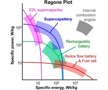
Fig. 1 Ragone plots for various electrochemical energy storage devices in comparison with internal combustion engines 1.
Electrochemical energy storage (EES) technologies are widely applied in personal electronics for many years.Nowadays, the fast increasing depletion of fossil resources and the concomitant environmental pollution further stimulate various researches and commercial interests in EES. Fig. 1 shows the Ragone plots of various EES devices in comparison with that of internal combustion engine1. Of all these,supercapacitors have unique advantages of higher power capability (comparable to that of internal combustion engines)and longer cycle life than, for example, rechargeable lithium ion batteries and redox flow batteries. However, it is desirable to obtain higher specific energy for the supercapacitors. According to the charge storage mechanisms, supercapacitors are divided into two categories: electrical double layer (EDL) capacitors and pseudocapacitors. The EDL capacitors based on carbon materials with high specific surface area (SSA) store electric energy by potential-dependent accumulation of electric charges from reversible adsorption of ions of the electrolyte onto the carbon/electrolyte interface to form the EDL within the porous carbon electrode. Taking a carbon negative electrode (negatrode)as an example, as revealed by Fig. 2, the EDL in fact has a multilayer structure, including the inner compact layer, outer compact layer and diffuse layer which is next to the bulk electrolyte solution1. Partially or fully desolvated ions exist in the compact layer. The specific capacitance of the EDL capacitor is roughly in proportion to the electrolyte ion accessible SSA of the carbon electrode. Pseudocapacitors rely on reversible faradaic (or redox) reactions in the active electrode materials, typically including transition metal oxides, metal hydroxides and conducting polymers2. The specific capacitances of pseudocapacitors are greater than those of EDL capacitors due to faradic reactions storing charges at the atomic or molecular levels. However, repeated expansion and contraction also occur in the electrode materials of pseudocapacitors during chargedischarge cycling. These are due to the ingression and egression of counter ions to maintain electric neutrality in the electrode materials, in response to the faradic reactions, leading to the well-known poor cycle lives of pseudocapacitors3. Similarly, the faradaic reaction caused expansion and contraction cycles and the consequent detriments also occur when charging-discharging lithium ion batteries repeatedly. Considering the advantages of high power capability, good cycle life and low cost, activated carbons (ACs) are currently the most popular commercial electrode materials.
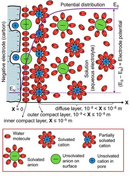
Fig. 2 Schematic representations of the EDL structure of the interface between a porous carbon negatrode and an aqueous electrolyte 1.
ACs are commonly derived by carbonization of carbon-rich precursors at high temperatures in an inert atmosphere and subsequent activation. In practices, KOH, H3PO4and ZnCl2are often used as the activating agents for chemical activation, while CO2and water steam for physical activation. The chemical activation procedures leave behind the combination of the disordered microporous and mesoporous structures in ACs by etching the carbonized specimens with these activating agents at high temperature. Therefore, ACs can possess typically the Brunauer-Emmett-Teller (BET) measured SSA ranging from 500 to 3000 m2·g-1and have specific capacitances of 100 to 300 F·g-1in organic or alkaline aqueous electrolytes, respectively4-6.In terms of structure, ACs are usually considered to be noncrystalline, whilst at atomic scales they are mainly composed of disorderly arranged graphene layers with various defects7. Thus,the properties of ACs are intrinsically linked to those of graphene.
Isolated and well-structured graphene layers were first reported in 2004, and considered to hold great promises for many applications. Such predictions are based on the fact that monolayer graphene has a very large theoretical SSA of 2630 m2·g-1, high carrier mobility over 10,000 cm2·V-1·s-1and extreme Young's modulus of 1.0 TPa8-10. In 2007, chemically converted graphene (called “graphene” for short in this review afterwards) was first prepared by reducing exfoliated graphite oxide (GO) with N2H4·H2O11. Then, graphene has been exploited as the electrode material of supercapacitors12.Subsequently, stable dispersions of graphene monolayers were obtained by adjusting pH during the reduction of GO with a suitable amount of N2H4·H2O13. Although experimentally obtained graphenes have SSAs far below the theoretic value,they still show specific capacitances similar to those of ACs,which can be attributed, at least partly, to the partial delocalization of valence electrons in oxygenated graphene according to a recent density functional theory modeling assisted study14. In this study, it was found that electron transfer reactions, also known as Faradaic processes, can be undertaken by localized or partially delocalized valence electrons. The former follows the Nernst equation and is featured by peakshaped cyclic voltammograms (CVs). However, the latter is responsible for the so called pseudocapacitance with the CVs having the same rectangular shape as that of a porous carbon electrode with high specific surface area and hence high EDL capacitance. This understanding explains well the differences between rechargeable battery electrodes which often show peakshaped CVs and supercapacitor electrodes which are well known for their rectangular CVs.
As revealed in Fig. 1, commercial EDL capacitors based on ACs could have specific energy of about 5 Wh·kg-1for the whole device. Comparing with rechargeable lithium ion batteries, the specific energy of AC based EDL capacitors is not high enough to meet the requirements of some power sources, especially in electric vehicles. The energy capacity (E) of a supercapacitor is defined by Equation (1),

whereQis the charge,Cis the total capacitance of the cell, andUis the cell voltage which is primarily related to the electrolyte used. The thermodynamic potential window of water is 1.23 V at room temperature, whilst organic electrolytes have higher decomposition voltages (above 2.50 V). Even if the specific capacitance in the organic electrolytes is a half of that in aqueous electrolytes, the energy of a cell in organic electrolytes is still higher because it is proportional to the square of the cell voltage.Nonetheless, organic electrolytes are usually highly flammable,making it more vulnerable when a high voltage is applied, which causes severe safety concerns. As for ionic liquids, their high viscosities at room temperature would induce even slower motion of the large organic ions, making it difficult and slow to access the internal surface of AC and hence very low specific capacitance. Therefore, the advantages of high conductivity and heat capacity, low cost and environmental impact of aqueous electrolytes have stimulated more research towards a breakthrough over the thermodynamic potential window of water. The extension of the cell voltage of an aqueous supercapacitor can be fulfilled by using electrode materials with high over-potentials for evolution of either or both hydrogen and oxygen gases.
In this review, attention is focused on the development in preparation of ACs from different precursors, and of graphenes in various forms in recent years. Then, the mechanism of extending the cell voltage and improving the performance of aqueous supercapacitors are introduced. Further, new trends of making better performing carbon materials for supercapacitors are introduced and discussed.
2 Activated carbon
As mentioned in Introduction, ACs are usually prepared by carbonization and subsequent activation steps. Natural materials,such as coconut shells and wood, are firstly selected as the carbon-rich precursors due to their low cost. Of course, synthetic materials can also be the carbon-rich precursors of ACs for specific purposes. A porous network in the body of carbon particles is produced after activation. The International Union of Pure and Applied Chemistry (IUPAC) categorizes pores into micropores (< 2 nm), mesopores (2-50 nm) and macropores (>50 nm) according to their diameters15. Generally, all of these can be created, but micropores dominate in carbon grains. Besides micropores, if markedly more mesopores are produced during activation, type IV nitrogen adsorption desorption isotherms can be observed. Otherwise, dominated micropores lead to type I isotherms. The most commonly used activating agent is KOH,with which the activation mechanism is governed by the reaction Equation (2).

Note that Equation (2) is thermodynamically unfavorable at temperatures below 700 °C, but it can proceed if the gaseous products are continuously removed. Particularly, the melting and boiling points of K are 63.38 and 758.85 °C, whilst KOH melts and boils at 360 and 1327 °C, respectively. Thus, even when K is produced at a sufficiently high temperature but below the boiling point, the liquid metal can still reach a sufficiently high vapor pressure and escape from the reaction sites. Comparing with KOH, the activation mechanism of ZnCl2 is more complicated. In the early stage of pyrolysis, ZnCl2works as a catalyst for the dehydrogenation and dehydration reactions of the precursor, inducing hydrogen evolution16, charring and aromatization of the carbon, and restricting the formation of tar17.We think that the restriction of ZnCl2 evaporation below 600 °C18and evolution of methane16correspond to the creation of pores in AC.
2.1 Activated carbon from biomass
Traditionally, the coconut shells as carbon-rich biomass wastes are the main precursor for the production of ACs.Nowadays, other biomass wastes, such as lignin19, bagasse20,loofah sponge21, willow catkin22,23, hemp bast fiber24and bamboo industrial byproduct25, can also be used as the carbon sources for making ACs.
Some natural biomass wastes were utilized due to their special microscopic morphology being similar to those of carbon nanotubes or graphene. Researchers expected to maintain the specific morphology during the production of AC in order to utilize more micropores for supercapacitors. For example, loofah sponges could yield ACs which exhibited a three dimensional(3D) network consisting of cross-linked hollow microtubes with wall thickness of around 2 μm21. Like carbon nanotubes, willow catkins show a hollow microtubular structure with the diameter of 10 μm and the wall thickness of 1 μm. The conventional twostep method consisting of carbonization at 600 °C for 4 h and activation with KOH by 4 times of mass at 800 °C for 1 h could produce hierarchical porous carbon microtubes, which are helpful for the diffusion of electrolyte ions into the inner micropores. In comparison, a control sample prepared by onestep activation without the carbonization could only exhibit irregular granular aggregates, which is entirely different from the natural tubular morphology of willow catkins22. Only the Type I N2adsorption and desorption isotherms could be observed,suggesting that mesopores were absent in the control sample.The BET SSA and the pore volume of the hierarchical carbon microtubes were 1776 m2·g-1and 0.85 cm3·g-1, respectively. The hierarchical carbon microtubes in 6 mol·L-1KOH electrolyte had a specific capacitance value of 292 F·g-1at 1 A·g-1in a threeelectrode cell. The morphology retention by the two-step method is likely because during carbonization at high temperatures,willow catkins should only undergo dehydration without any significant alterations in the carbon skeleton (structure), whilst the follow-on activation could only attack the remaining carbon structure, according to Equation (2). However, in the one step method, the KOH could attack both the willow catkins precursor and its carbonization products at different stages of the process,and hence destroy the original morphology.
Another biomass waste is hemp bast fiber that can be converted to crumpled graphene-like carbon nanosheets24.During the fabrication, the hydrothermal treatment of hemp bast fiber in a dilute acid solution at 180 °C for 12 h replaced the conventional carbonization at high temperatures, which could potentially reduce the production cost. The bamboo-based industrial byproduct was also treated by the hydrothermal method in a liquid containing sulfuric acid at 200 °C for 12 h before activation. The final bamboo-derived carbon was subjected to post vacuum annealing at 800 °C for 1 h after activation25. The BET SSA of 1472 m2·g-1and the specific capacitance of 301 F·g-1(in 6 mol·L-1KOH in a three-electrode cell) were obtained for the three-step treated bamboo-derived carbon. If direct pyrolysis at 800 °C for 2 h was applied instead of the hydrothermal treatment, the control sample possessed 96% micropore volume, giving a slightly lower SSA of 1106 m2·g-1. Another control sample without post vacuum annealing also showed a lower specific capacitance, indicative of the importance of the hydrothermal treatment and the post vacuum annealing.
Obviously, not all biomasses have the desired morphology and structure. Instead, new structures to enable specific functionalities are often needed to build from the precursors. For example, gelatin, a biological extractive from animal syndesm,could turn to a honeycomb-like porous structure with glutaraldehydeviafreeze drying, which gave AC with a maximum BET SSA of 3692 m2·g-1up to date. The specific capacitance of 305 F·g-1for a single electrode was obtained in a symmetrical two-electrode cell26. Also, opportunities are always sought after to further lower the energy input for AC production.In this line, a new method was developed to achieve molecular level one-step activation to prepare AC with agar as a precursor which is the extractive from seaweed27. The dehydration (or deoxygenation) of agar was achieved by dissolving agar in a hot KOH aqueous solution below 100 °C. It was observed that the color of the aqueous solution turned dark black. The increased C/O molar ratio of such treated agar samples was attributed to the removal of hydrogen bonded hydroxyl groups and cyclic ether linkage of six member rings in agar by a dehydration reaction with KOH in the hot solution, as revealed by infrared(IR) spectra (Fig. 3a). Surprisingly, the one-step activation of agar in the subsequent calcination produced an interconnected 3D network with macrovoids of several micrometers with a wall thickness of several hundred nanometers. The control sample processed by the conventional two-step method presented bulk characteristic with fractured large macrovoids, suggesting that the molecular level activation occurred in the one-step calcination (Fig. 3c and d). Therefore, the one-step derived AC possessed a larger SSA of 1672 m2·g-1and total pore volume of 0.81 cm3·g-1which compare favorably with 1048 m2·g-1and 0.47 cm3·g-1for the two-step derived AC, respectively. The specific capacitance of the one-step derived AC was 226 F·g-1in a three-electrode cell, 38% higher than that of the two-step derived AC (Fig. 3b). The symmetrical two-electrode cell with an electrolyte of 6 mol·L-1KOH also exhibited a maximum specific capacitance of 57 F·g-1at 0.25 A·g-1, corresponding to 228 F·g-1for a single electrode. The improved charge storage performance should be attributed to the unique 3D morphology and pore characteristics whilst the low temperature and high efficiency production is indicative of the commercial potential of the molecular level one-step activation.
Comparing with the conventional two-step method, an extra vacuum post-treatment could increase the capacitive behavior of AC, however, the cost per kWh·g-1is still high. Therefore,molecular one-step activation has a better promise in commercial preparation of AC. The bottleneck to commercial development of the one-step process is the relatively low yield of AC.
2.2 Activated carbon from polymers
Apart from natural biomass, synthetic materials were also used to prepare ACs, aiming at controllable morphology,porosity or component. Phenolic resin is one of the most conventional synthetic materials as the carbon precursor due to its high carbon yield and structure stability. Although other synthetic materials are inferior to phenolic resin in terms of cost and production scale, they also have potential applications in AC industry particularly when they are spent or out of period of validity. A dye intermediate, (2-benzimidazolyl) acetonitrile(C9H7N3), could form AC with a high SSA of 2980 m2·g-1during the pyrolysis with KOH. However, most of the N element in the precursor was not retained at such a high temperature. The C9H7N3-derived AC showed 286 and 221 F·g-1in capacitance at 0.5 A·g-1in 2 mol·L-1KOH and 1 mol·L-1Na2SO4 electrolyte in the two-electrode cells, respectively28. Conductive polymers,for instance polyaniline29, binders, such as polyvinylidene fluoride (PVDF)30, polytetrafluoroethylene31, and dispersants,including polyvinylpyrrolidone32, were all attempted as carbon precursors. Among these facile synthetic precursors,polyaniline-derived AC showed a high specific capacitance of 455 F·g-1in a three-electrode cell containing 6 mol·L-1KOH,while PVDF-derived AC exhibited a large SSA of 3000 m2·g-1.Considering that polyaniline could be designed to vertically grow on GO, AC with structure combination of 1D and 2D was produced after carbonization and activation, giving a specific surface area of 2416 m2·g-1with a total pore volume of 1.88 cm3·g-1, which is higher than those of polyaniline-derived AC33.
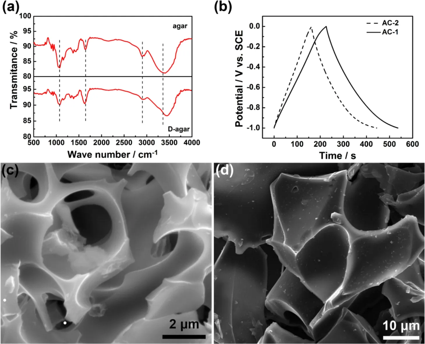
Fig. 3 Molecular level one-step activation of agar 27.
Additionally, polymers with peculiar molecular structure,such as poly[(pyrrole-2,5-diyl)-co-(benzylidene)]34and triazine-based covalent organic polymer35, were expected to lead to regular-structured ACs as well as hetero-atom doping.However, the nitrogen content in these ACs from complicated N containing co-polymers as precursors were not beyond 5%atomic fraction when they were subjected to higher-temperature activation. Fortunately, morphology could be often retained after carbonization and activation at high temperatures. Interestingly,poly-N-phenylethanolamine (PPEA) yielded AC with peculiar morphology.N-phenylethanolamine (PEA) surrounded with hexadecyltrimethylammonium bromide were polymerized by ammonium peroxydisulfate (APS). The shell of the polymer which was produced at the initial reaction prevented further reaction between APS and the interior PEA, perhaps leaving oligomers of PEA within the shell. Therefore, the PPEA-derived AC showed a peanut-shell-like morphology after one-step activation (Fig. 4)36. As a result, a BET SSA of 3103 m2·g-1was obtained by activation at 800 °C, corresponding to 356 F·g-1at 1 A·g-1in a three-electrode cell with 1 mol·L-1H2SO4.
Although the cost of synthetic polymers may be high, their spent or waste forms can be precursors of ACs for special applications. The benefits from using synthetic polymers as the precursors for ACs are the designation of special morphology,structure and even component, which may result in higher performance.
2.3 Graphitic activated carbon
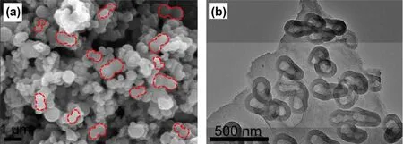
Fig. 4 (a) SEM and (b) TEM images of PPEA-derived AC 36.
Although hemp bast fiber could be converted to crumpled graphene-like carbon nanosheets, the very much desired graphitization in relevance to, for instance, conductivity and structural stability was not observed in the products. In order to give rise to graphitic ACs, a graphitic catalyst precursor of FeCl3 and another activating agent of ZnCl2were introduced simultaneously into the skeleton of the coconut shell. One-step calcination completed the graphitization with activation only at 900 °C in N2. The transmission electron microscopy (TEM)images in Fig. 5a and b indicate 11 graphene layers in the graphitic AC nanosheets. The graphitization was associated with the transformation from Fe3+ions to carburized phase to Fe at a high temperature, as revealed by the XRD pattern (Fig. 5c). The Fe components could form a carburized phase during the heating process, and decomposition of the carburized phase could lead to the graphitization to form graphene-like nanosheets37. The Raman spectrum (Fig. 5d) showed an evident 2D band at 2743 cm-1and a high intensity ratio of the G to D bands, suggesting that the graphitic AC nanosheets were composed of few layers of graphene according to the Raman theory38. The BET surface area and total pore volume of the graphitic AC nanosheets were 1874 m2·g-1and 1.21 cm3·g-1. Although the BET SSA of the control sample, non-graphitic AC, reached a higher value of 2007 m2·g-1, its specific capacitance of 210 F·g-1was lower than 268 F·g-1for the graphitic AC nanosheets as measured in a threeelectrode cell. The symmetric two-electrode supercapacitor with the 6 mol·L-1KOH electrolyte had a specific capacitance of 69 F·g-1at 1 A·g-1, corresponding to 276 F·g-1for a single electrode, similar to that in the three-electrode cell. These differences were attributed to the high electronic conductivity facilitating the efficient ionic and electronic transport. However,it may also be attributed to the pseudocapacitance resulting from partial delocalization in the more graphitic sample14.
Another crumpled graphitic carbon nanosheets were prepared by the same method plus a post vacuum annealing with inner shaddock skins as a precursor39. Although the macroscopic shape of inner shaddock skins was similar to graphene, the 2D band on the Raman spectrum was not very sharp. It suggests that the graphitization induced formation of graphene was perhaps much more associated with the component than macroscopic shape. However, thesp2/sp3ratio doubled comparing with crumpled carbon nanosheets prepared without using FeCl3as the catalyst.
2.4 N doping
It is known that doping with hetero-atoms, for instance N, is an effective strategy to increase the specific capacitance of carbon materials, probably due to the resulting pseudocapacitance and wettability to electrolytes. NH3is a commonly used nitrogen source and can be flown into the heat treatment reactor to prepare N-doped ACs. When the corncobs were employed as the precursor, which was mixed with KOH and subjected to the NH3flow, the nitrogen mass fraction of the N-doped AC increased from 2.97% at 400 °C to 3.98% at 600 °C40.However, much increased oxidized pyridinic N was found in the N-doped AC heated at 600 °C, which was considered to have resulted in the capacity drop in the organic LiPF6 electrolyte compared with that at 400 °C.
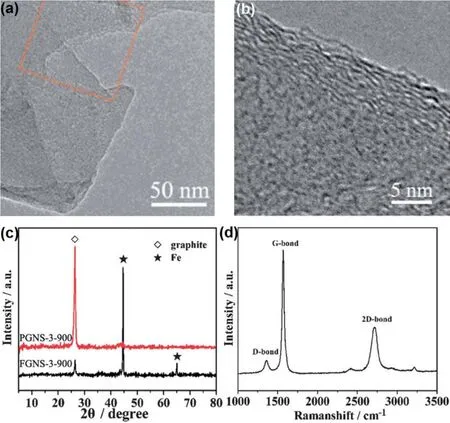
Fig. 5 Graphitization of AC from coconut shell using FeCl3 catalyst 37.
As mentioned above, phenolic resin is one of the most conventional synthetic materials and can be used as the carbon precursor, particularly when it is spent. The change of components, such as N doping, can be readily fulfilled during the reaction for the synthetic materials. Melamine with a high N content was added to the formaldehyde and resorcinol solution41.The slow thermal oxidation at 250 °C in air stabilized the thermoplastic structure and increased the N content. After carbonization and activation, a high N mass fraction of 12.5%and an SSA of 2234 m2·g-1were detected in the synthetic N-doped AC. The symmetrical two-electrode cell in 3 mol·L-1H2SO4showed a specific capacitance that is equivalent to 309 F·g-1for a single electrode. Similarly, 3,3'-diaminobenzidine could react withp-benzoquinone to produce a polymer (PDB)with high N and O contents. Luckily, after pyrolysis with KOH,11.0% of N and 10.4% of O mass fraction remained in the resulted AC, which showed an SSA of 2660 m2·g-142. A specific capacitance of 72.5 F·g-1(290 F·g-1for a single electrode) at 0.2 A·g-1was obtained in a two-electrode cell in 6 mol·L-1KOH,corresponding to a volumetric capacitance of 29.7 F·cm-3.
Fresh egg white is a natural nitrogen-rich source. The precipitated protein by ethanol was pyrolyzed at 650 °C for 2 h and further activated at 550 °C for 2 h under Ar atmosphere43.Carbonization and activation at relatively low temperatures in Ar retained 6.5% of N mass fraction. An increased O mass fraction of 16.5% was detected in the sample after activation. High specific capacitances of 556 and 525 F·g-1were measured in three-electrode cells containing 1 mol·L-1H2SO4and 1 mol·L-1KOH, respectively. The egg white derived AC as the negatrode was constructed an asymmetrical device with a NiCo2O4-graphene composite as the positive electrode (positrode), giving 1.55 V in cell voltage and 48 Wh·kg-1in specific energy.
Incorporation of melamine during the preparation of the precursors gave rise to the highest N content among the three examples mentioned above, showing the advantage of making N-doped ACs from precursors with a high N content. Natural nitrogen-rich sources are advantageous in their lower costs and sufficiently high N contents that can be transferred into the produced ACs. Obviously, NH3 annealing is more facile than incorporation of melamine, but the produced AC contained the lowest N content.
2.5 Activated carbon with templates
As ZnO presents various morphologies by different synthetic routes and can be readily removed by acid, it is an ideal nonporous template for building hollow structure. For example, ZnO nanorods grown on the Ni foil were utilized as a template to gain hollow Ni arrays by electrodeposition. Subsequent hydrothermal treatment and calcination of glucose and removal of ZnO nanorods induced carbon spheres on hollow Ni arrays44.Similarly, flower-like ZnO was fabricated by the reaction between zinc nitrate hexahydrate and trisodium citrate in the NaOH solution. Pitch was coated on the flower-like ZnO and then carbonized and activated. After elimination of the template,the flower-like morphology was maintained for the resulting hierarchical AC which had an SSA of 761.5 m2·g-1and a pore volume of 0.49 cm3·g-1, higher than 375.8 m2·g-1and 0.45 cm3·g-1respectively for the control sample, i.e. the flower-like carbon without activation45. The symmetric two-electrode supercapacitors in 1 mol·L-1Na2SO4had a stable voltage of 1.8 V, delivering a maximum specific energy of 15.9 Wh·kg-1.
The MgO powder can also be used as a non-porous template to produce carbon nanolayers by pyrolysis of glucose as the precursor. After KOH activation, the SSA increased from 936 m2·g-1for the carbon nanolayers to 2798 m2·g-1for the AC nanolayers calculated by the BET theory, arising from hierarchical microporosity and mesoporosity by the chemical activation46. Chitosan was used as the precursor in another similar work47.
Recently, porous MgO was exploited as a template, prepared by calcination of Mg(OH)2layers formed by boiling MgO powders48. Carbonization of coal tar pitch in tetrahydrofuran impregnated into the porous MgO generated pillared-porous carbon on the upper and lower surfaces as well as on the pore walls of the templates49. The distance between the two carbon layers was 10-20 nm and the thickness of the individual carbon layer was 2 nm. The mesopores of 6-8 nm were perpendicularly aligned to the surface of the carbon layer.
2.6 Activated carbon from metal-organic frameworks
Metal-organic frameworks (MOFs) have well defined nanocavities and open channels, and are ideal templates for making porous carbon materials. Based on this idea, MOF-5(Zn4O(OOCC6H4COO)3) was initially selected as a microporous template, in which furfuryl alcohol vapor was filled and polymerized. The carbonization of the composite was performed at 1000 °C for 8 h under an Ar flow50. ZnO was formed by the decomposition of MOF-5 between 425 and 525 °C and then reduced to Zn metal above 800 °C, which vaporized away at temperatures beyond its boiling point, 908 °C. Carbon species finally was left alone with a BET SSA of 2872 m2·g-1and a pore volume of 2.06 cm3·g-1, showing a specific capacitance of 258 F·g-1at 0.25 A·g-1in a three-electrode cell containing 1 mol·L-1H2SO4.
When a commercially available MOF sample containing no oxygen, Zeolitic Imidazolate Framework-8 (ZIF-8) was employed as a template to replace MOF-551, it was found that the control sample, ZIF-8 as the only precursor without polymerized furfuryl alcohol, could also yield porous carbon with a SSA of 3148 m2·g-1. Since then, MOFs as the only precursor and self-template were widely researched. The ZIF-8 directly derived carbon retained a typical crystal morphology which was similar to that of the parent ZIF-8, as shown in Fig.6. The sample prepared at 900 °C gave a BET SSA of 1075 m2·g-1and a specific capacitance of 128 F·g-1in a threeelectrode cell using 0.5 mol·L-1H2SO4as the electrolyte52. It was found that ultrasonication during the synthesis of ZIF-8 could yield an extra small amount of mesopores and macropores.The sonicated ZIF-8 derived carbon had a BET SSA of 1955 m2·g-1and a pore volume of 1.21 cm3·g-1. After activation with KOH, the SSA of the sonicated ZIF-8 derived AC increased to 2972 m2·g-1and the pore volume to 2.56 cm3·g-1. The specific capacitance of the sonicated ZIF-8 derived AC was 211 F·g-1at 10 mV·s-1for a single electrode, which was higher than 170 F·g-1for the ZIF-8 derived AC without sonication and 158 F·g-1for the sonicated ZIF-8 derived carbon without activation in a two-electrode cell containing 1 mol·L-1H2SO453. The increased performance was attributed to extra hierarchical pores produced in ZIF-8viaultrasonication. However, when MnO2 was redox deposited on sonicated ZIF-8 derived porous carbon materials which were reacted with KMnO4at room temperature, the specific capacitance of MnO2-inactivated carbon was higher than that of MnO2-AC, which was considered to be due to the hierarchical porous structure in MnO2-inactivated carbon54.Additionally, ZIF-8 particles with uniform sizes were synthesized as the precursors by cooling the reactants of Zn2+and 2-methylimidazole before reaction55.
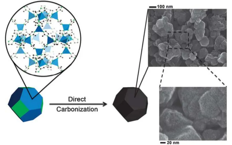
Fig. 6 Scheme of direct carbonization of ZIF-8 to produce the Z-900 carbon sample and its SEM images 52.
Further, the perfect copy on the morphology from MOF precursors to ACs had been demonstrated by strong evidence when MOF-74 rods were used as the precursor. MOF-74 can be made into rod shapes in the presence of salicylic acid as a modulator. The pyrolysis of the rod shaped MOF-74 could form carbon nanorods, proving the maintenance of the morphology.Surprisingly, upon ultrasonication and activation with KOH, the carbon nanorods were transferred to six-layered graphene nanoribbons. The N2sorption analysis for the graphene nanoribbons showed a typical type II isotherm with an SSA of 1492 m2·g-1. The specific capacitance of the graphene nanoribbons was 168 F·g-1at 1 A·g-1for a single electrode as derived from the measurement in a two-electrode cell containing 1 mol·L-1H2SO456. It was found that the formation mechanism of graphene nanoribbons from carbon nanorods was similar to that from oxygenation of carbon nanotubes57, which also thanked to maintenance of the rod shape from the MOF precursors.
Table 1 summarized the fabrication of ACs using different precursors and their performance for aqueous supercapacitors in this section.
3 Graphene
Stable dispersions of graphene monolayers were revealed by AFM, signifying a breakthrough in fabrication of graphene from the exfoliated GO. The stable dispersions of graphene could form graphene films by vacuum filtration13. The graphene film can be a supercapacitor electrode directly without any binders and conductive additives. In order to facilitate the electrolyte permeation within the tight structure of the film, the electrolyte was pre-incorporated into the electrode before the desiccation of the film58. Besides the 2D film form in macrograph, two categories of 3D graphene networks with macropores were prepared. One of these is the graphene hydrogel prepared by the hydrothermal treatment of GO in a static state59and the other is the graphene foam by chemical vapor deposition (CVD) on the Ni foam as a template60. Additionally, graphene fibers were also fabricated by an injection61or casting-like62methods.
3.1 Powders
Large scale production of graphene powders with few layers would be possible by the reduction of GO in aqueous colloids or in furnaces. For liquid reduction, different reducing agents wereattempted to reduce GO, such as N2H4H2O11, NaBH463, NaOH64,hydroquinone65, p-phenylene diamine66, vitamin C67, HBr68and HI69. The most popular method to produce the stable graphene dispersions consisting of monolayers is reduction of GO colloids with N2H4H2O as the reducing agent in an ammonia-adjusted pH environment13. Rapid annealing in an inert atmosphere could also reduce solid GO powders to fewlayer graphene with a lower level of residual oxygen70. In order to prevent the restack of graphene after annealing, Mg(OH)2 powders were used to be templates to obtain the graphene sheets with distinctly crumpled morphology (Fig. 7)71. The furnace technology could make microporous graphene with a high SSA upon KOH activation72, following the same mechanism as that for activation of ACs73. Mesoporous graphene powders were prepared with SnO2 deposited on GO. The SnO2 acted as catalysts for carbon gasification, yielding perforations of 5-10 nm in size on the graphene nanosheets (Fig. 8)74.
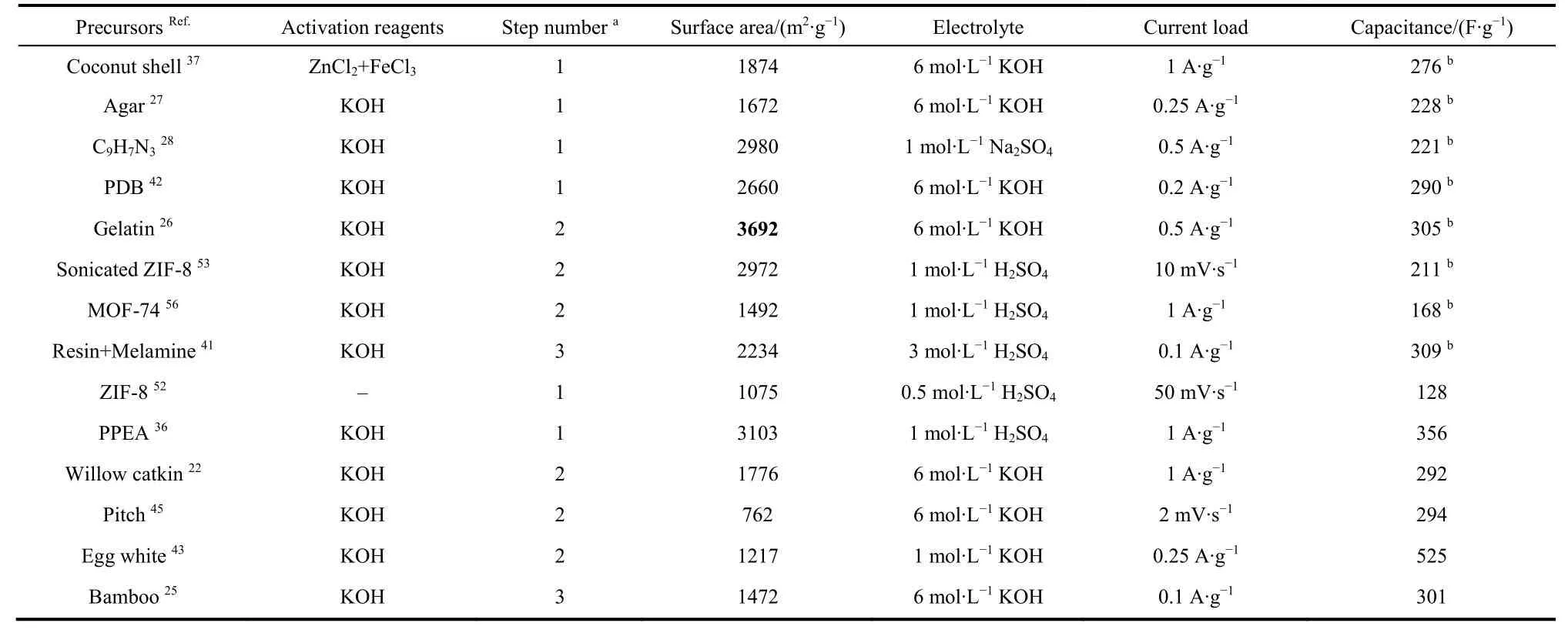
Table 1 Fabrications and performances of ACs for aqueous supercapacitors.
Recently, a self-propagating high temperature synthesis (SHS)technology was designed to fabricate scalable mesoporous graphene75based on the magnesiothermic reaction, which could be expressed as Equation (3)76,77.

A current of 3 A passing through the tungsten coil embedded in the mixture of Mg and MgO for only 5 s created a combustion wave. The excited energy ignited Mg powders in a sealed CO2atmosphere to trigger the SHS course, during which MgO acted as spacers to prevent the restack of graphene75. The SHS-made graphene had an SSA of 709 m2·g-1with unimodal pore distribution at 4 nm which was consistent with the size of the MgO template. 98% ofsp2hybridization occupied the SHS-made graphene, resulting in high electrical conductivity of 13000 S·m-1, which should be beneficial to achieving high power supercapacitors. As SHS is a furnace technology with low cost due to the very short heat impulse, it promises a high potential for commercialization of graphene once the layer numbers could be further decreased during the SHS.
Besides CO2, carbon nanodot could be another new precursor to prepare macroporous graphene. A 40 W CO2 laser was also applied to irradiate thermolyzed carbon nanodots at low temperature using a laser engraver. Laser irradiation induced a decarboxylation of the upper lying carbon nanodots and released gases, enabling the formation of graphene with spongy micron porous structure78.
Building pores on graphene basal planes by activation or catalytic oxidation could increase specific capacitance of graphene materials, however, it also brought about materials with low density, which direct resulted in low volumetric capacitance of graphene and consumed superfluous electrolyte.Further, extra electrolyte would increase the weight of the supercapacitor, leading to a low specific energy for the whole device. Molten salt methodology, a metallurgical electrochemistry technology, was developed to fabricate electrode materials in electrochemical energy storage. Treatment of graphene in NaNH2molten salt simultaneously achieved densification and perforation effects, producing a high packing density of 1.2 g·cm-3for the electrode and 3-5 nm pores on graphene basal planes79. The molten salt treated graphene delivered a specific capacitance of 435 F·g-1and a volumetric capacitance of 522 F·cm-3at 1 A·g-1in 6 mol·L-1KOH electrolyte in a three-electrode cell. It is worth noting that the volumetric capacitance of the molten salt treated graphene is 5.4 times as that of untreated graphene, which unveiled the application potential of molten salt methodology for supercapacitors.
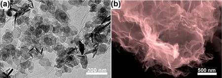
Fig. 7 (a) TEM image of Mg(OH)2 on GO, (b) SEM image of crumpled graphene after removing Mg(OH)2 template 71.

Fig. 8 TEM images of (a) SnO2 on GO, (b) the medium after SnO2 on GO being subjected to controlled air oxidation(c) final mesoporous graphene nanosheets after removing SnO2 74.
3.2 Films and aerogels
Graphene films could be preparedviavacuum filtration of stable dispersions, having an outstanding tensile modulus. They can be directly used as electrode without binder and conductive additive. Some graphene composite films were also madeviavacuum filtration of the dispersion of graphene composites. A slightly different example was a graphene film that was intercalated with MnO2on carbon sphere. MnO2was produced on etched carbon sphere between the interlayer of graphene films using KMnO4 as an oxidant, giving 66.3% of the MnO2 in the composite film80. The specific capacitance was 319 F·g-1at 1 A·g-1as measured in a three-electrode cell in 1 mol·L-1Na2SO4.After 5000 cycles at 5 A·g-1, 94% of the initial capacitance retained. These results indicate a synergistic effect between the pseudocapacitive and EDL capacitive storage mechanisms in the composite material.
A graphene aerogel with an interconnected 3D macroporous network was discovered in the course of the hydrothermal processing and subsequent freeze drying59. In order to establish mesopores in the graphene aerogel, H2O2was employed during the hydrothermal course to partially oxidize and etch the carbon atoms on the more active defect sites of GO. Compressing the holey graphene hydrogel before freeze drying produced the holey graphene film81, which had an SSA of 810 m2·g-1, which was much higher than 260 m2·g-1for the aerogel without oxidation by H2O2. The electrolytes were integrated before compression of the holey graphene hydrogel. The holey graphene film with pre-integrated 6 mol·L-1KOH electrolyte had a specific capacitance of 310 F·g-1as derived from measurements in a two-electrode cell.
A pristine GO hydrogel could be obtained by adding a small amount of HCl to the GO dispersion until the pH value reached 0.6582. The GO hydrogel was paved on a glass substrate by blade-casting. The graphene film was obtained by reducing the spread GO hydrogel in a mixed solution of HI and CH3COOH83.The GO hydrogel derived graphene film with a thickness of 388 μm exhibited a high tensile strength of 1 MPa, affording 400 g weights. The areal capacitance of the film was 71 mF·cm-2at 1 mA·cm-2as measured in a two-electrode cell with 1 mol·L-1H2SO4.
ZnCl2 was found to be an activating agent to tune microporous structure in the graphene aerogel without pulverization. The graphene hydrogel was soaked in the ZnCl2solution. After being subjected to vacuum drying and annealing for 1 h under Ar, the microporous graphene aerogel still retained the columnar morphology (Fig. 9)84. The activation temperature of 600 °C induced the formation of micropores and simultaneously maintained the bulk density with the highest efficiency. The remaining columnar structure with higher bulk density suggested that ZnCl2could be a relatively mild activating agent, compared with KOH, which could balance between the maintenance of structure and production of micropores. The increase of the bulk density of graphene aerogels meant higher energy density of graphene supercapacitors for practical applications.
3.3 Foams
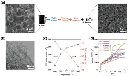
Fig. 9 Porosity tuning of graphene aerogel with ZnCl2 84.
Ni foams with 3D interconnected macropores are often used as current collectors to enhance electrolyte accessible surface of active materials. It was found that the stable functional graphene colloids prepared fromp-phenylene diamine were positively charged in organic solutions66. Graphene nanosheets were loaded on the Ni foams by electrophoretic deposition and subsequent annealing in Ar (Fig. 10)85. The specific capacitance of the graphene on the nickel foams was 139 F·g-1at 3 A·g-1in a three-electrode cell with 6 mol·L-1KOH.
Free-standing graphene foams were prepared using Ni foams as sacrificial templates and catalysts in a CVD process, in which the Ni foams were exposed to CH4in Ar/H2for 5 min at 1000 °C,followed by rapid cooling60. The graphene foams could be immersed in the fresh mixture of the polyaniline precursors,producing graphene-polyaniline composites for supercapacitors86.
Polyurethane (PU) sponges had a similar structure to that of the Ni foam and were used as the template to clone graphene foams. The specific capacitance of the sponge-templated graphene was 57 F·g-1at 10 mV·s-1in the 0.5 mol·L-1NaCl electrolyte87. In order to obtain graphene foams with high specific capacitances, an activation approach was applied, in which the mixture of 1 mg·mL-1GO and 10 mg·mL-1KOH dissolved in a homogeneous suspension was sucked into a PU sponge and annealed at 900 °C for 2 h in an Ar flow88. No products were left when pure sponges were annealed in Ar,indicative of complete pyrolysis. Therefore, the only product was activated graphene which possessed micropores and mesopores besides the copied macroporous structure from the sponges. The activated sponge-templated graphene had an SSA of 2582 m2·g-1, which was twice of that of the activated graphene formed without using the sponge template. The increased SSA could indicate that the sponge templates prevented the aggregation of GO. A specific capacitance of 188 F·g-1was obtained at 1 A·g-1for the activated sponge-templated graphene in 6 mol·L-1KOH as measured using the two-electrode cell. The sponge-templated method is more facile than the Ni foamtemplated CVD process to prepare graphene for supercapacitors.The activation step in the sponge-templated method prevented aggregation without compromising the desired high bulk density, which favoured to obtain high energy density of supercapacitors.
3.4 Fibers
Macroscopic GO fibers were assembled by injecting GO dispersion into a coagulation bath using a syringe and rolled onto a drum. HI was used to reduce the GO fiber into graphene fiber61.Another work proposed a technology that a graphite tip as a positrode could withdraw graphene fibers from reduced GO nanoribbon colloids at a constant voltage89.
The most facile method to prepare graphene fibers might be baking the GO suspension at 230 °C for 2 h, which was injected into the glass pipeline with a 0.4 mm inner diameter by a syringe.During the course of baking, graphene sheets aligned directionally to the fiber's main axis and became densely stacked, resulting in the fiber diameter reduced to 35 μm62. The as-prepared graphene fibers were very flexible and could be woven to various shapes and structures and embedded into the polydimethylsiloxane matrix. When inserting a stainless steel needle into a branched glass tube with a capillary tip, a hollow GO fiber could be spun in a coagulation bath (Fig. 11)90. An electrodeposition method was applied to grow the 3D graphene sheath on the solid graphene fiber core in the electrolyte comprising of GO aqueous suspension and LiClO4. A flexible all solid state fiber supercapacitor was fabricated by intertwining the two graphene fiber core-sheath electrodes pre-coated with the H2SO4-PVA gel91. Its specific capacitance reached 25-40 F·g-1, while the areal capacitance and linear capacitance were 1.2-1.7 mF·cm-2and 20 μF·cm-1for a single electrode. A compressible and stretchable spring-like supercapacitor was fabricated by wrapping the wet fiber supercapacitor, the areal and linear capacitances of which were close to those of the fiber core-sheath supercapacitor. Based on this method, a hollow graphene-conducting polymer fiber was fabricated by injecting a mixed solution containing GO, poly(3,4-ethylenedioxythiophene):poly(styrenesulfonate) (PEDOT:PSS) and the reducing agent of vitamin C into a glass pipeline92. The hollow structure was configured by releasing gases during the reduction reaction of GO.
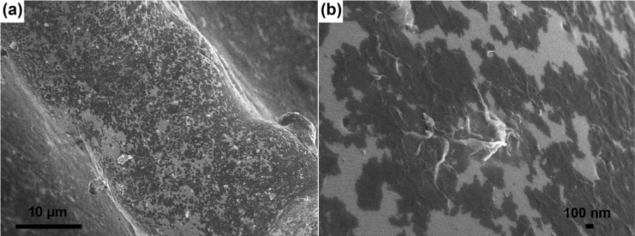
Fig. 10 SEM images of graphene nanosheets on Ni foams by electrophoretic deposition in (a) low and (b) high magnification 85.

Fig. 11 SEM images of the (a) cross-section and (b, c) surface of hollow GO fiber with rapidly freeze-dried treatment 90.
The naissance of the fiber structure enriched the macroscopic structure of graphene. Since then, 3D graphene aerogels and foams, 2D graphene films and 1D graphene fibers could have been applied in various flexible forms of supercapacitors.
The textiles, such as cotton yarns, could also be employed as the core to grow GO fibers. An electroless deposition process was exerted to produce Ni-coated cotton yarns. GO grew on the Ni-coated cotton yarns as a working electrode by electrolysis of GO in LiClO4at a constant potential in a three-electrode cell.After reduction by the hydrazine vapour, the graphene on Ni coated cotton fiber was obtained93. The volumetric capacitance of the composite fiber was 292.3 F·cm-3for a single electrode at a current density of 87.9 mA·cm-3in 1 mol·L-1Na2SO4as measured using a two-electrode cell. Its linear capacitance was 0.11 F·cm-1in the PVA/LiCl gel electrolyte. Because the graphene on Ni coated cotton fiber possessed a fairly high tensile strength due to the metallic coating, it could be made into embroidery or woven into a fabric. Another example to realize the graphene fabric with giant area into clothes was to deposit graphene-polyaniline onto the polyester textile by dip-coating.The silver paste was screen printed onto one side of the textile electrode as the current collector grid, which could increase the electrical conductivity of the whole textile electrode94. For a 16 cm2supercapacitor textile, the areal capacitance reached 781 mF·cm-2at 0.5 mA·cm-2, corresponding to a specific capacitance of 152 F·g-1based on the total mass of graphene and polyaniline. In the absence of the current collector grid made by the silver paste, a very low areal capacitance of 0.08 mF·cm-2was obtained at the same current density, indicative of the important role of the current collector grid in a textile electrode with a large area. However, the electrodeposition or immersion coating could not achieve a thick electrode on textile, let alone maintaining the porosity throughout the entire electrode thickness. To address the challenges, an alternating vacuum filtration of the dispersion of carbon nanotubes (CNTs) and graphenes through Ni-coated cotton fabric on the top of PVDF was applied95. A remarkable mass loading of 23.7 mg·cm-2was achieved for the CNT-graphene on textile electrode. More importantly, the alternating filtration maintained nanoporous structures, resulting in the one-bilayer and ten-bilayer electrodes with similar BET values of ca. 160 m2·g-1. The ultrahigh areal capacitance of 6.2 F·cm-2was achieved for a single electrode at a fairly high current density of 20 mA·cm-2in the 5 mol·L-1LiCl aqueous electrolyte, possibly being one of the best EDLC electrodes to date. The specific capacitance of the CNT-graphene on textile electrode reached a constant value of 250 F·g-1regardless of the thickness. All solid state symmetrical supercapacitor textiles in the PVA/LiCl gel electrolyte were sealed with hydrophobic polyester fabrics and treated by a water repellent spraying. The volumetric capacitance of the electrode was 107 F·cm-3at 20 mA·cm-2. The feasibility to increase the area and thickness of the electrodes with proportionally enhanced performance opens an avenue toward wearable applications with high areal capacitance.
Table 2 listed the performance of graphene for aqueous supercapacitors in this section.
4 Unequalisation of electrode capacitances
4.1 Mechanism
The main disadvantage of the aqueous supercapacitors is that their specific energy is not as high as those in organic electrolytes, including ionic liquid, let alone lithium ion batteries. This is understandable because, according to Equation(1), the cell voltage is more decisive than specific capacitance of the electrode materials for the specific energy. The theoretical voltage for water decomposition into hydrogen and oxygen gases is 1.23 V, which would limit the specific energy of aqueous supercapacitors. Fortunately, the gas evolution reactions in the electrolyte are also affected by the interaction of the electrode materials with the electrolyte, which may be affected by pH. It was demonstrated that a neutral electrolyte, KCl, had a potential window of 2.00 V which is wider than those of acidic and alkaline electrolytes96. Nevertheless, the cell voltage of the symmetrical AC supercapacitor in a neutral electrolyte of Li2SO4could not be higher than 1.60 V to ensure a stable performance97.
Because the nascent hydrogen produced from water decomposition is immediately absorbed in the micropores of AC, an overpotential for H2 molecule formation and gas evolution is needed. The theoretical potential for H2 evolution on the AC electrode was calculated to be -0.38 Vvsthe normal hydrogen electrode (NHE) at pH value of 6.4. For the MnO2electrode, positive scanning of the polarization potential isexpected to invoke either the reactions of Mn(IV) to Mn(VII) or O2evolution from water decomposition. In a neutral or low pH electrolyte, O2 evolution may occur at a potential more positive than the thermodynamic equilibrium potential, largely because H+could be generated on the MnO2electrode under positive polarization, making it difficult for H2O oxidation to produce the O2gas. The positive polarization potential achieved a maximum at pH of 6.4, resulting in an extension of the cell voltage to 2.00 V for an asymmetrical supercapacitor in a neutral electrolyte assembled from a MnO2 positrode and an AC negatrode98.
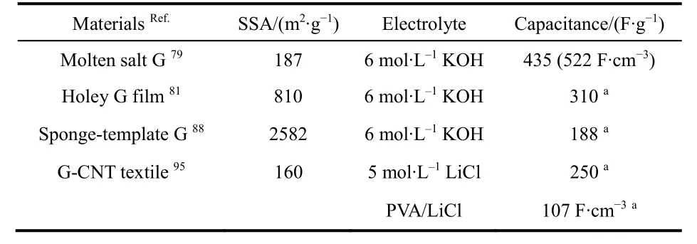
Table 2 Performance of graphene (G) for aqueous supercapacitors.
The amount of charge,Q, stored in each of the positrode and negatrode must be the same, which is governed by Equation (4),

whereCpandCn,CpmandCnm, andUpandUnare the capacitances, specific capacitances, and potential ranges of the positrode and negatrode, respectively. Conventionally, in the symmetrical supercapacitors, capacitance equalization of the two electrodes is a necessity to maximize specific energy because the positrode and negatrode have the same working potential range. Generally, the exploitable potential range of a positrode,is narrower than that of the negatrode,in many asymmetrical cells with an AC negatrode, e.g. (-) AC | neutral aqueous electrolyte | MnO2(+). When the positrode and negatrode in an asymmetrical supercapacitor are equalized in capacitance like in the symmetrical one, the cell voltage will be limited by the positrode with a smaller exploitable potential range. Ideally, the cell voltage should cover the whole exploitable potential ranges of positrode and negatrode. AsCpm andCnmare determined by the nature of the electrode materials,the mass ratiomp/mnis related to the potential ranges of the positrode and negatrode. AlthoughUnandUpare next to each other,may be often overlapping partially. It was found that the cell voltage andUn increased with increasingCp/Cnin the asymmetrical supercapacitors assembled by electrodeposited polyaniline (-) and AC (+) in an acidic electrolyte (Fig. 12a)99.More importantly, the equi-potential, or the potential of zero voltage,E0V, i.e. the potential at the fully discharged state,moved towards more negative values, which was deduced by a small charging peak on the CVs of the asymmetrical cell corresponding to the constant potential of 0.78 VvsAg/AgCl for the polyaniline electrode as well as Equation (4). It meant thatUp also slightly increased. The specific energy had the same increasing trend as the cell voltage. Hence, the mass ratiomp/mnis tightly associated with the potential of zero voltage100. In fact,E0Vin the experiments was not consistent with the estimation,for instance, the potential of Mn(IV) to Mn(II) reduction for the(-) AC | neutral aqueous electrolyte | MnO2 (+) asymmetrical supercapacitors. Increasing the mass ratio, i.e.Cp/Cn, was tried to extend theUnand the voltage of the (-) AC | neutral aqueous electrolyte | MnO2(+) cell101. Monitoring the cycle life is the more convincing and reliable way for validating a cell, rather than the coulombic efficiency in the initial charge-discharge cycles.
Conventionally, asymmetrical supercapacitors were assembled by different materials with different exploitable potential ranges to gain a higher cell voltage than the symmetrical ones. However, the asymmetrical concept could extend to the same material with different masses if the material behaves differently in different exploitable potential ranges. A commercial Cabot Monarch® 1300 pigment black (CMPB)exhibited a very wide potential window in neutral electrolytes when measured in a three-electrode cell, reaching close to 2.20 V in K2SO4. However,E0Vis closer to the positive potential limit of the CMPB electrode, so that the symmetrical supercapacitor had only a 1.60 V cell voltage. Unequalization of electrode capacitances was achieved by using the same CMPB material of different masses (hence different capacitances) to make the positrode and negatrode, hence the actually exploited potential ranges of the two electrodes,UnandUp, were adjusted, leading to a sufficiently high maximum cell voltage of 1.90 V with a stable cyclic performance (Fig. 12b)102. When the asymmetrical cell was charged to 1.9 V, the initial positive potential limit was as high as 1.05 VvsAg/AgCl, but dropped to and stabilized at about 0.86 V after 800 cycles until the end of cycling test (6000 cycles). In a separate test in the three electrode cell, the positive potential limit was found to be 0.90 V. Thus, this final stable potential of the positrode at 0.86 V in the cycling test is the evidence that anodic oxidation of the CMPB electrode should have been responsible for performance decay when the cycling test was carried out at cell voltages higher than 1.90 V. However,it was also noticed that the stable negatrode potential recorded in the cycling test was still about -1.00 V, far more positive than the negative potential limit of -1.4 V for the CMPB electrode.This is indication that there is still room to further increase the cell voltage, calling for more investigation.
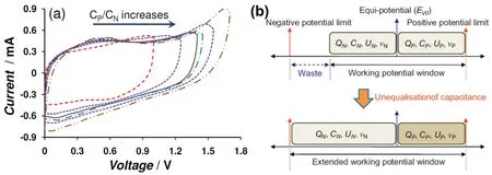
Fig. 12 (a) CVs of asymmetrical supercapacitors with CMPB negatrode and a PAN-CNT positrode at various Cp/Cn ratios with the charging current peak at the same scan rate 99. (b) A strategy to increase the operating voltage of supercapacitors with the same material for both the positrode and negatrode via unequalisation of electrode capacitances 102.
The specific energy,Esp, of a supercapacitor (cell) is calculated by Equation (5) below.

whereCcellandUare the capacitance and maximum cell voltage of the supercapacitor, andm+andm-are the masses of the positrode and negatrode, respectively. Interestingly, ifCcell,Uand the sum of (m++m-) are all fixed constants, Equation (5)predicts a maximumEspwhenm+=m-. This is obviously not the case in the above discussion in relation with Equation (4) which allows changes in bothCcellandU. Further, what is not mentioned in both Equations (4) and (5) is the importance of the equi-potential of zero voltage,E0V, which is a key parameter to determine bothUnandUp. It is worth noting that in conjunction with equi-mass principle of Equation (5), the equi-potential of graphitic materials, typically graphene, could be adjusted in an organic 1 mol·L-1LiPF6electrolyte. After electrochemical charge injection, the originalE0Vof 3.50 V of graphene was adjusted to 1.16 VvsLi/Li+, resulting in a cell voltage increase from 3.00 to 4.30 V103.
4.2 Asymmetrical supercapacitors
A classic example of asymmetrical supercapacitors is that assembled with a MnO2positrode and an AC negatrode in a neutral aqueous electrolyte. The (-) AC | KNO3| MnO2(+)supercapacitor was found to a maximum specific energy of 21 Wh·kg-1when the cell voltage reached an optimal 2.00 V when the pH was 6.84 for the electrolyte98. Instead of AC, graphene was used to make the negative electrode in the asymmetrical supercapacitor. The MnO2nanowires were loaded on graphene as the positrode material in order to increase the electric conductivity. The (-) graphene | 1 mol·L-1Na2SO4| MnO2-graphene (+) asymmetrical supercapacitor had a specific energy of 30 Wh·kg-1at a small specific current (0.1 A·g-1)104. Then, a microwave treatment was applied to irradiate the KMnO4 in graphene suspension, leading to a high specific capacitance of 310 F·g-1at 2 mV·s-1for the synthetic MnO2-graphene composite. Therefore, the (-) AC | Na2SO4| MnO2-graphene (+)cell reached a specific energy of 51 Wh·kg-1at 2 mV·s-1while the cell voltage was 1.80 V105. Although Mn3O4had lower specific capacitance than MnO2106, it seemed that the birnessite Na0.5MnO2nanosheets prepared by electrochemical oxidation of Mn3O4viacyclic voltammetry (CV) in the Na2SO4electrolyte were attractive because of an extended exploitable potential range107. The specific capacitance was 311 F·g-1at 1 A·g-1.When Na0.5MnO2was combined with Fe3O4-C107or AC108, the cell voltages reached 2.60 and 2.70 V while the specific energies were 81 and 61 Wh·kg-1, respectively. It was also found that the Ni0.25Mn0.75O arrays with AC could achieve a cell voltage of 2.40 V when a new phase transformation occurred to the poorly crystallized LiNi0.5Mn1.5O4electrode after CV activation in the LiCl aqueous electrolyte109.
Some other commonly claimed asymmetrical supercapacitors include (-) AC | acidic aqueous electrolyte | conductive polymer(+) and (-) AC | alkaline aqueous electrolyte | Ni-Co oxide (+).The former is a good example of the combination of an EDL capacitive negatrode with a pseudocapacitive positrode. The latter, however, comprises a positrode made from NiCo2O4110-112,Co(OH)2113, Ni(OH)2114, and Ni-Co layered double hydroxide115.Whilst these electrochemical cells should be capable of charge storage, they are not truly supercapacitors because the Ni-Co oxides or hydroxides behave more like a battery electrode material. These hybrid electrochemical cells are now defined as supercapattery which is beyond the scope of this review.
5 Conclusions and outlook
In conclusion, activated carbons (ACs) are generally good materials for making either the positrode or negatrode or both in supercapacitors. They can be prepared by the conventional twostep method, including carbonization and activation at high temperatures. The precursors for making ACs, including those with special shapes similar to that of carbon nanotubes and graphene, have been shown to be crucial in affecting the properties of the produced ACs. Although the extra post vacuum annealing can improve the electrical and electrochemical properties, the molecular level one-step activation method can be a better choice for production of ACs from some biomass precursors of low structural orders with a low cost and high performance. Graphitization of AC can be fulfilled by FeCl3 catalysis during the activation, which increases the electrical conductivity. Hetero-atom doping is also an efficient means to add pseudocapacitance into the carbon materials. Template method can produce the hierarchical porous structures in carbon materials which facilitate the electrolyte transfer. Metal-organic frameworks used as a self-template and a new carbon precursor can give rise to tailored porous carbon or graphene, which have novel academic values.
Graphene can also be the excellent electrode materials for supercapacitors due to large theoretic specific surface area and the partial electron delocalisation by residual O atoms according to the recent developed theory. Various structures of graphene can be made as electrode materials for supercapacitors, including graphene powders, graphene films, graphene aerogels, graphene foams and graphene fibers. Activation can also produce micropores in graphene, which is like those in AC. Selfpropagating high temperature synthesis can produce mesoporous graphene powders by the magnesiothermic reaction, while molten salt technology mesoporous graphene with a high packing density. Macroporous graphene hydrogel can be produced by hydrothermal treatment of graphite oxide suspension. The graphene hydrogel can also be transferred into the film structure. Hierarchical porosity can be yielded by H2O2 etching or ZnCl2activation of the macroporous graphene hydrogel. Activated graphene foams can be prepared by sucking the mixture of GO and KOH using sponges as templates, which can exert high performance in supercapacitors. Graphene fibers prepared by the cast-like method can be used a core to grow graphene by electrodeposition. Additionally, graphene based materials can grow on the textile by electrodeposition, dipcoating or filtration, which can be weaved into clothes with large area or thick loading. These graphene based fibers and textiles have a promise application in flexible and wearable supercapacitors.
Besides the desirable specific capacitance arising from the optimal AC and graphene electrodes, the cell voltage is paramount to increase the specific energy for supercapacitors.Extension of cell voltage is rationally fulfilled by asymmetrical supercapacitors, in which the balance of the charge in the positrode and negatrode must be complied with. Increase ofCp/Cncan thoroughly utilize the whole exploitable potential ranges of the positrode and negatrode in the aqueous asymmetrical supercapacitors.
High energy consumption during calcination, low packing density and yield of carbon are the main bottleneck in fabrication of ACs for industrial application. Recently, carbon spheres were loaded within the macropores in rice straw-derived carbon116.Therefore, filling nano-micro carbon into the macropores in bulk ACs is also a facile method to increase packing density of carbon. As we know, activation is a carbon removal process which produces CO2gas and leave behind micropores in bulk carbon. When carboxymethylcellulose sodium, a binder with high O content, was used as a precursor, too little product is to be collected. It is reported that Mg powders could lead to a carbon regeneration process when reacting with released CO2during activation of carboxymethylcellulose sodium117.Although metal Mg is very expensive, the carbon regeneration process to balance the carbon removal process during activation is a new thought to improve carbon yield.
Two new trends in the development of aqueous supercapacitors have emerged. Firstly, when the redox active hydroquinone was added into the electrolyte (which is then referred as a redox electrolyte) of a carbon based supercapacitor,a large increase to 900 F·g-1in specific capacitance was claimed118. Similarly, addition of the redox active salt of K3Fe(CN)6 in the aqueous electrolyte could lead to confinement of the salt or its ions in a solid-like state within the electrode, and hence the counter ion effect to increase the specific capacitance of the carbon electrode119,120. Whilst recognizing the contribution to charge storage capacity, it has been pointed out that the increased charge storage capacity from the redox electrolyte is actually Nernstian (i.e. battery-like). Therefore, the device is no longer a supercapacitor, and hence its storage performance should not be analyzed in terms of capacitance121. The term supercapattery is more appropriate for description of such hybrid devices in which charge storage is achieved in both the capacitive and Nernstian mechanisms1,122. The other trend of development is the application of the 3D printing technology in fabrication of micro-supercapacitors, which requires the ink of the electrode materials with appropriate viscosity as well as shear-thinning rheological properties123.
The innovation in the production of AC and graphene may bring out the prospect toward supercapacitors with high performance and low cost. The incorporation of the redox components and the 3D printing technology are two of the new trends to develop aqueous supercapacitors. With the unremitting efforts from multidiscipline, it is believed that the AC and graphene materials from new precursors and production methods can open up a significant vista for aqueous supercapacitors in the near future.

