
Strength Properties of Timber Beams Reinforced with CFRP Sheets*
2020-03-20 01:33XUEMeihuiWANGJianxing
吉首大学学报(自然科学版) 2020年1期
XUE Meihui, WANG Jianxing
(School of Civil Engineering, North China University of Technology, Beijing 100144, China)
Abstract:Based on finite element analysis (FEA) in ABAQUS software, a numerical simulation was proposed to accurately describe the damage behavior and performance of the model.Nonlinear constitutive relationships and other characteristics of different materials, influencing factors such as the length of CFRP, the layer number of CFRP and the wood interface under finger joints were under consideration.The results show that the ultimate bearing capacity is increased by CFRP.The stress is mainly concentrated on the CFRP material.
Key words:component model; finger joint; timber beams; CFRP
1 Introduction
For about a century, wood has been used as a solid structural elements for construction.Since wood is a renewable and sustainable material (which acts as a CO2sink) with excellent strength-to-weight ratios, its use in construction is increasing[1].It has recently been shown that the right choice of building materials is essential to improve the energy efficiency of buildings[2].These elements may then be combined with a binder to form a large variety of rigid structural members as beams and columns used in assembling wooden structures for structural purposes are becoming wise and economical.Compared with conventional beams, finger point beams are usually manufactured by removing the strength-reducing defects for higher stiffness,higher strength and reducing the variability in mechanical properties, which allows for tailor-ability,enhancing straightness, dimensional stability and infinite.Therefore, finger joint wood beams have obvious product durability, serviceability and fatigue performance and dimensional stability and so on.Finger point grafting techniques are always challenging to join two wood samples together.Thus, end joints are able to transmit a significant target strengths though they generally represent only a small portion of structural components, which have recently been found in ref.[3-8].
Many studies have found strength and stiffness enhance-ments for wood beams using FRP composites[9].The use of FRP materials not only enhances the solid wood beams, but also strengthens the bending elements in production.Recently, basalt fiber reinforced polymers have been used to enhance the technical effect of other composite beam reinforcement processes, and several other advantages were pointed out elsewhere[10-11].
Industrial processes do not always satisfy the accuracy of the results.Finger joint strength will be lower than solid wood.The main goal of this work was to evaluate the quality of plywood joints, which focuses on controllable factors related to the production process.Typical adhesive bond lines in wood structures have a thickness between 0.1 and 1 mm, which is several orders of magnitude less than the typical length of a structural element[12].It is assumed that finger joints must resist high loadings, and the mechanical strength is one of the major performance requirements.In order to develop the product structure of finger-jointed more efficiently the adhesive bond line specific process parameters must be considered.Even under good manufacturing conditions, the strength of the knuckles of the fingers is lower than the traditional one.The type of adhesive and the curing time are worked by loading processes, timber and CFRP experience large plastic deformations leading to cracks presented in the structure before the CFRP is bonded.Factors that affect finger joint strength include the finger geometry (the width of the pitch,the finger length, the pitch and the tip gapand the slope), wood density (moisture,etc.), and natural defects(the irregular grains and knots), and the factors associated with the bonding process can also affect the final performance[13-18].In many cases, the behavior of the adhesive line is modeled by the FE method.The effects of contour stress and damage evolution on finger joints, including geometric parameters, are analyzed and discussed.Current work should be paid to strengthening the use of CFRP materials to analyze the important role played by beams in bending tests, which is considered to refer to joint capacity.Although the strength of the joint and the chemical nature of the binder play a key role, the corresponding studies were considered to be beyond the scope of current work.Timber is a widely used structural material by the construction industry.It is strong and lightweight, having strength for a weight ratio of 20% higher than that of the structural steel but it ages faster than other building materials, such as reinforced concrete[19].The behavior of the finger-jointed wood members is usually affected by bending, overload or atmospheric, biological, chemical or insect attack, etc.,so the initial damage to the structure is taken.Enhancing the use of CFRP materials in pure bending is particularly suitable for the nature of wood[19-21], which is suitable for using carbon fiber reinforcements to reinforce and repair wood is an interesting option for steel.
However, CFRP material is made of multiple layers (steel cord, adhesive, carbon fiber reinforced plastic),lighter than steel and high strength, the combination of wood and carbon fiber composites is difficult to model.On the other hand, cracks are usually present in the structure prior to CFRP bonding.Then, the structure is initially destroyed.Wood structural members need to be reinforced in the weakest area.Compared with unreinforced beams, the reinforced beams have increased load carrying capacity and energy absorption capacity[22-24].In fact, the latter mainly records the bearing capacity of the cross section.Initial damage to the wood samples, such as knot defects, initial expansion in the stretch zone, and the carrying capacity of the wood components are reduced to a much higher extent than the compression zone.Tensile zones, stiffeners, steel plates and fiberglass materials are among the most common reinforcement technologies[23-24].This approach significantly increases the ability of the beam to bend in ref.[25-26].The use of FRP materials not only enhances the solid wood beams, but also strengthens the bending elements in production[9, 27-30].Recently, basalt fiber reinforced polymers have been used to enhance the technical effect of other composite beam reinforcement processes, and several other advantages were pointed out elsewhere[25, 31].Raftery and Kylie[25]analyzed the mechanical properties of low-grade binders and basalt fiberglass rod bending test laminated wood structure reinforcement technology, the results show that the use of basalt fiberglass rods can effectively repair damaged wood components.
2 Constitutive Equations of the Model
The plasticity model in this study is based on the frame work of the mo-dynamic approach.The state relations are given as
σ=(1-D)Λ∶εe,
(1)
R=(1-D)Q×r,
(2)
(3)
σrepresents the Cauchy stress component,εethe elastic strain component,Λa function of Young moduli, (R,r) the isotropic hardening stresses,Rthe scalar variable,rthe parameter andQthe isotropic hardening modulus.
The post-softening elasto-plastic model describes the closure of the crack under loading.The compression behavior is based on Hill's isotropic hardening yield criterion, which is related to the flow rule and correctly describes the one-way flow.Dis stiffness factor related the MOE.The fourth-order symmetry elastic property tensor can be written as:
where
D1111=E1(1-ν23ν32)γ,D2222=E2(1-ν13ν31)γ,
D3333=E3(1-ν12ν21)γ,D1122=E1(ν21+ν31ν23)γ,
D1133=E3(ν13+ν12ν23)γ,D2233=E2(ν32+ν12ν31)γ,
D1212=2G12,D3131=2G3,D2323=2G23.
The plastic potential describes plastic flow, which is written as:
with,
TheF,G,H,L,MandNyield from quadratic Hill yield criterion (Hill,1948) are given as
wherea1111=G+H,a2222=F+H,a3333=F+H,a1122=-H,a2233=-F,a1133=-G,a1212=2N,a2323=2M,a1313=2L.
The Yamada-Sun strength criterion is used for wood:
The constitutive equations are integrated over time increment:
The plastic consistency criteria should satisfy the conditionfn+1which satisfy the consistency condition at timetn+1:
Considering the initially elastic, the trial stress is obtained at timetn+1as:
The trial stress substitutes to the the failure criteria, then yields:
with

with
The final system of equations are obtained with the Newton-Raphson method.
hn+1(Δλ,nn+1,Dn+1)=Λ∶(σn+1-Xn+1)-‖σn+1-Xn+1‖nn+1=0,
3 Failure Mode Description
In this part, the model is used to simulate the finger point beams' capacity of spruce wood.A three-dimensional plane stress analysis model is applied to support solid wood and finger joints to carry out three point bending static loads.The geometry of the finger-point and the further detailed size of the finger are shown in Table 1 while part of the finger joint is shown in Fig.1.The moisture content of finger joint specimens is 12% and the corresponding 12% density is 460 kg/m3averagely.Then the final required specimen is planned, and the cross-sectional area is 80×42 mm2.Table 2 showes constants of wood material.
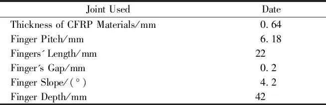
Table 1 Geometrics of Finger Joint Beam
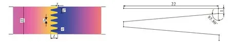
a Geometry of the Finger-Point b Detailed Size of the JointFig. 1 Geometry of Tested Specimen
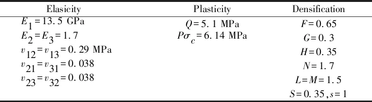
Table 2 Constants of Wood Material
The present work must evaluate the behavior of spruce wood bend in full scale, in order for evaluating the bearing capacity of spruce timber beams reinforced with CFRP materials material.The finger-joint beam is tested with unreinforced materials in the absence of control beam[33].The other specimens are strengthened with different reinforcement lengths and different two layeres (one layered 932, two layered 932, 426, 252 mm).The CFRP materials are considered to be linearly orthotropically anisotropic until failure.All carbon fiber composite materials have a thickness of 0.6 mm and their mechanical properties as adhesion properties are shown in Table 3.

Table 3 Constants of CFRP Material and Adhesive Properties
4 Test Results
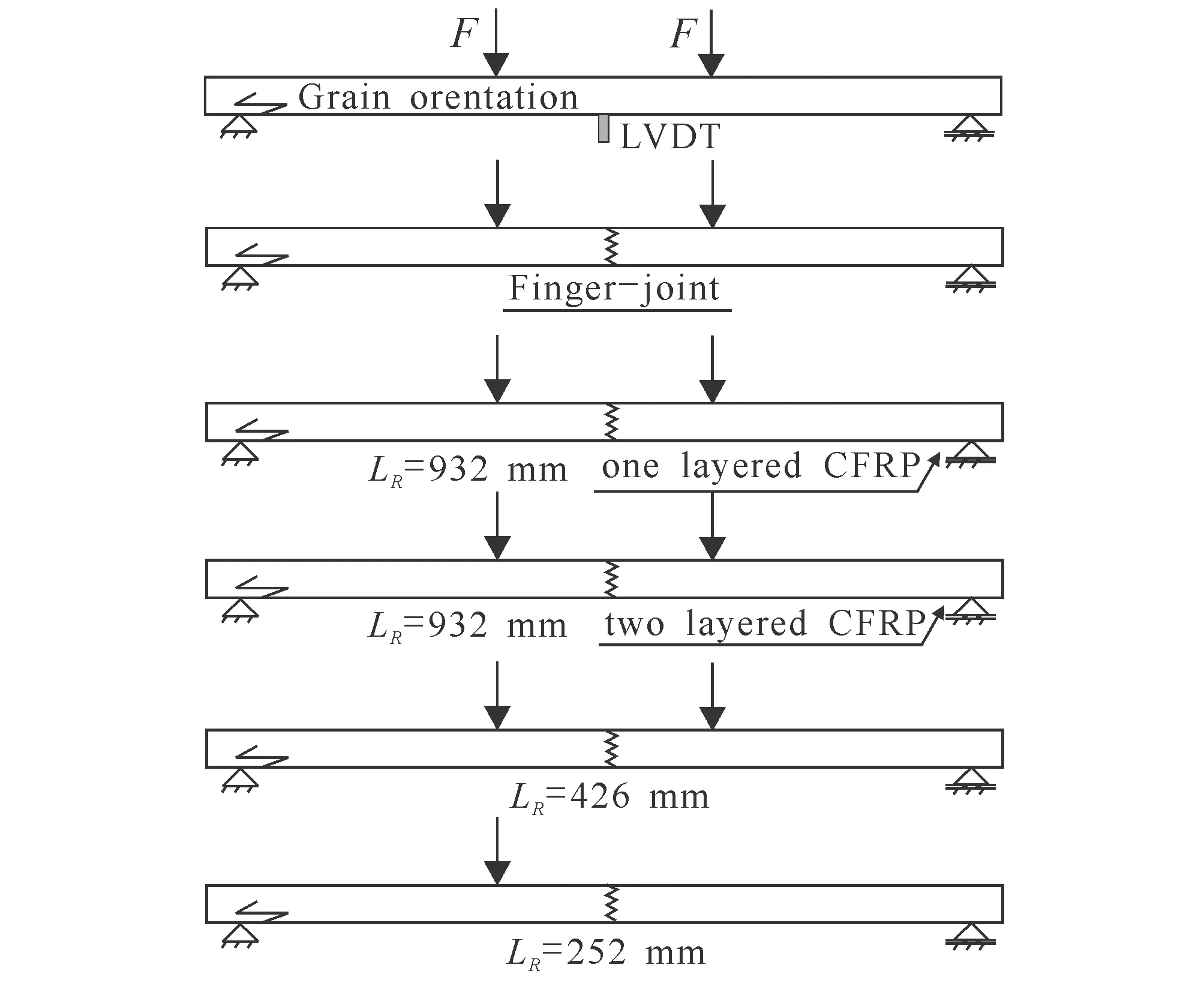
Fig. 2 Geometry of Tested Specimens
The geometry of tested specimensof the finger-joint beam is shown in Fig.2.The bending behavior used for spruce wood is analyzed and the finger joints are placed at the center of the sample.Fig.3 showes the overall response of the four different reinforcement finger beams (a layer of 932, two layers of 932, 426, 252 mm) on the load and displacement maps.On the unreinforced finger beams, the results showes that the bearing capacity is significantly reduced.The limit load of the un-reinforced beam is lower than the limit load of the control series about 43.6%.
For non-reinforced beams (series CT) with no finger joints, each curve consistes of linear and nonlinear parts.For the un-reinforced and reinforced finger,the sudden break is due to the presence of the joint (un-reinforced and reinforced series), each curve containing only one linear part.As a result, the global behavior is not flexible.Fig.4 showes the failure modes of the finger-joint.Fig.5 showes the global responses in terms of load versus displacements plots for four different reinforced finger-point beams (one layered 932, two layered 932, 426, 252 mm).

a Finite Element (Overall Scales)

b Finite Element (Details)Fig. 3 Finite Element Model of the Finger-Joint

Fig. 4 Sudden Break in the Presence of the Finger Joints

Fig. 5 Load-Midspan Deflection Curves
For the control beam, the maximum displacement is 23.40 mm.In addition, this behavior is non-linear.The corresponding force is equal to 12.58 kN.The test piece showes bending damage in the outermost wood laminate of the beam, followed by the fracture of the CFRP composite panel.
Fig.6 showes the strain and stress distributions of the control beam.The test piece showes bending damage in the outermost wood laminate of the beam, followed by the fracture of the CFRP composite panel.For one reinforced layer beam (932), the bearing capacity response is reduced to 8.8 kN at maximum displacement (29.58 mm).For two reinforced layered beams (932), the bearing capacity response is reduced to 10.8 kN at a displacement of 33.78 mm.The model showes cracks in the outermost wood laminate on the tensile side of the beam, followed by debonding of CFRP composite sheets from adjacent wood laminates and delamination in CFRP sheets in some places.For the finger beam reinforcement beam with 426 mm CFRP material, the bearing capacity response drops to 7.68 kN at a displacement of 18.27 mm.For the finger beam reinforcement beam with 252 mm CFRP material, the bearing capacity response drops to 7.58 kN at a displacement of 17.39 mm.This example showes very clearly the effect of CFRP on the overall properties of wood.The failure occures in the stretching zone and propagates to the compression zone.
As shown in Fig.5,the ultimate load of the series with four different reinforcement lengths (one layered 932, two layered 932, 426, 252 mm) are higher than those of the unreinforced finger beams.

Fig. 6 Strain Distributions of the Finger-Joint
5 Conclusion and Perspectives
The finite element model is used to study CFRP enhanced finger joints.A theoretical model based on irreversible process demage is used to describe the coupling between the elastic-plastic anisotropy of wood and damage.The mechanical behavior of wood is characterized by the combination of elasto-plastic anisotropic behavior and isotropic ductile damage, and the behaviour of CFRP is characterized using inelastic behavior.In addition, a cohesion FE model is also used to solve the interface behavior between CFRP and wood.
The retical and numerical simulations are discussed in detail.From the current study, the following conclusions can be drawn:
(1)Non-linear behavior is observed during loading.However, the behavior of finger joints that are not reinforced and reinforced prior to failure is completely linear.This linearity is due to the presence of knuckles and a significant decrease in the bond strength.
(2)In general, reinforcing the behavior of the finger-joint components indicates a sharply increase in the capacity of the unstiffened elements.In most situations, cracks begin tension zone and are connected to the compression zone propagation.
(3)The bonding model used can represent the interaction between CFRP and wood.
