Conceptual design, modeling and compliance characterization of a novel 2-DOF rotational pointing mechanism for fast steering mirror
Muhmmd ABID, Jingjun YU,*, Yn XIE, Adus SALAM
a Robotics Institute, School of Mechanical Engineering and Automation, Beihang University, Beijing 100083,China
b School of Aeronautic Science and Engineering, Beihang University, Beijing 100083,China
KEYWORDS Compliant mechanism;Finite element analysis;Graphical approach;Rotational stiffness;Sensitivity analysis
Abstract In this paper,a novel 2-DOF rotational pointing mechanism(RPM)is designed inspired by the guidelines of the graphical approach. The mechanism integrates with a fast steering mirror(FSM)for compensating pointing errors of a laser beam.The design intends to achieve an angular travel of±10 mrad and steers a 25 mm mirror aperture.A planar flexure with beam flexures accompanied in parallel with an axial flexure build-up mechanism configuration. Compliant mechanismbased RPM ensures high precision and compactness. Compliance characteristics are established based on the stiffness matrix method for four different planar flexure layouts.One layout with best in-plane rotational compliance is then assessed for performance sensitivity to mechanism dimension parameters and parasitic error,thus informing the design space.Rotational stiffness in both the inplane rotational axes and stress is determined based on finite element analysis(FEA).The wire electrical discharge machining (EDM) is employed for developing the proof of concept for the RPM and is then assembled in FSM. Experiments are conducted to determine the rotational stiffness and angular travel about both in-plane rotational axes. Comparison among theoretical, numerical and experiments reveal excellent linearity of rotational stiffness along the rotational travel range.The maximum theoretical error is less than 5.5%compared with FEA while,the experimental error has a mean of 5%and 3%for both rotational axes thus satisfying the intended design requirement.
1. Introduction
Free space optical communications (FSO) technology1has intensive potential to provide high data transmission between terminals of varying distances spanning from few to thousands of kilometers. Optical data transmission finds utilization in laser-guided weapons,2precision pointing instruments,3target tracking laser radar,4un-manned aerial vehicles (UAV),5fast trains, between satellites, deep-space communications6and bio-medical systems.7However, pointing errors are generated when intense weather and atmospheric conditions cause impairment of optical signals by misaligning terminals connecting the receiver with the transmitter. The instances of uncertainty in tracking system, swing of a transceiver, fixture vibration or stress in electronic and mechanical components in optical communication systems may result in total loss or degradation of received signals.
Pointing errors are compensated via FSM8incorporating rotational pointing mechanisms. The main components that constitute the FSM include a reflective mirror for directing laser beam; flexure mechanism for driving the mirror; actuators to provide desired angular travel;sensors for mirror position monitoring and housing for the integration of components mentioned. Such a mechanism then compensates pointing errors by acquiring remote targets, aiming and locking laser beam towards a target during unfavorable circumstances including motion of target, random jitter and turbulence in the atmosphere. Over the years various classic tip-tilt steering scanners have appeared for angle alignment and guidance applications utilizing needle-like support springs,9pivot pin on a pivot bearing mechanism10,11and cone-ball bearing mechanism.12Conventional machine elements comprised these mechanisms having friction, stick and slip effect and wear hence, compromising the precision and performance of the mechanism.
A compliant or flexure mechanism13is a class apart from traditional rigid-body mechanisms that rely on its intrinsic elastic deformation for transferring the motion, force or energy. Apart from the advantages of compliant mechanisms the type synthesis in compliant mechanisms with desired performance goals is still a challenge. Compliant mechanismbased RPM needs to fulfill desired mobility requirements and be constrained for the remaining degree of freedom(DOF). Compliance analysis14determines the relationship between the applied load and deformation of the mechanism and has been the focus of many researchers. In this context Awtar et al.15while working on compliance analysis and synthesis for beam-based flexures developed a compliance matrix and recently generalized the proposed constraint model for 2D beam flexures.16Pei et al.17proposed pseudo rigid body models to analyze motion characteristics of flexible leave based cartwheel hinges. Symmetry in flexure mechanism design improves the mechanism functionality in a substantial reduction of sensitivity of thermal and buckling load.18The stress build up over the desired DOF should be monitored and remain within the elastic limit or below the materials yield limit.19Design approaches for flexure mechanisms include pseudo-rigid-body model (PRBM) approach20and constraint-based design (CBD).21,22These approaches are either not suitable for the distributed compliant mechanism or require tedious mathematical calculations. These methods are further limited in their substantial requirement of designer’s experience for guiding a suitable design. On the other hand, the graphical approach23is underlined by screw theory, with a widespread application for both designing and analyzing compliant and rigid body mechanisms24; thus enabling the early-stage design of the flexure system using sketches on paper and eliminating the need for complicated mathematics. Graphical patterns introduced by Blanding25assist in the visualization of freedom and constraints for a mechanism. While working on compliant parallel mechanism Yu et al.26highlighted the significance of the graphical approach in the conceptual design process. The graphical approach relies on the geometric shapes quantitatively containing information. This information characterizes a flexure system in two distinctive sets of geometric figures for DOF and degree of constraint (DOC) characterization. A possible flexure design is then visualized based on geometric sets for fulfilling a specific motion and constraint scenario.
Several studies focusing on the design of beam steering mechanisms have incorporated a combination of several genres of flexure hinges either in series or in parallel.27,28The designer’s intuition and experience seemed to be the general guideline in devising the freedom and constraint topology of designed pointing mechanisms. In a study conducted for free-apace laser communication, Aoki et al.29devised a widerange fine pointing mechanism. The mechanism comprised a flexible support system integrating center torsion bar and four thin springs.The working highlighted the performance characteristics of the mechanism in rotating a 20 mm diameter mirror but lacked in providing compliance characterization and design implementation method. Loney8has also worked on FSM for driving a 20 mm diameter mirror for in-plane rotations. His design was meant to increase the bandwidth rejection for disturbances based on closed-loop response. The study highlighted the mechanism configuration components but is found to be limited in providing a theoretical guidance and compliance characterization of the flexure design. Long et al.27designed a mechanism for tip-tilt motion via a thin flexible diaphragm based flexure support system but lacked in providing a deterministic design guideline for achieving desired compliance. In a study conducted on the fast steering mirror,Wu28have focused on the detailed design and validation of a power-efficient voice coil actuator(VCA)with limited elaboration of flexure suspension design. The works studied so far regarding the design of pointing mechanisms have either demonstrated limited provision for the conceptual design and theoretical guidance or lacked in providing a detailed compliance characterization and their experimental validation.
Hence, this research is motivated to conceptual design and characterization of compliance of a novel RPM intended to achieve precise in-plane rotational motions. The conceptual design of the mechanism is inspired by the graphical approach.After that, it is incorporated in the FSM assembly. The RPM comprises a planar flexure possessing a monolithic parallel structure with symmetric arrangement of beam flexures and an axial flexure orthogonal to planar flexure. The activity of mechanical design in high precision required applications demands the analysis of mechanism compliance. In this context,analytically compliance calculations based on the stiffness matrix method for our proposed RPM are conducted. Thereafter the compliance factors so obtained define the mechanism elastic response. Compliance characteristics are evaluated for four different planar flexure layouts in MATLAB. These layouts are differentiated based on the number and arrangement of beam flexures.The layout with best in-plane rotational compliance is proposed for compliance sensitivity and parasitic error to mechanism dimension parameters. The FEA of RPM is implemented to find out the rotational stiffness and stress about both in-plane rotational axes over the angular travel range. Moreover, a physical prototype is manufactured using wire EDM and the experiment is performed to determine the rotational stiffness over the angular travel. A comparison of theoretical, FEA and experimental results are presented to evaluate the design.
The remainder of this paper is organized as follows. The conceptual design approach and FSM geometry are detailed in Section 2.Compliance characteristics are determined analytically in Section 3 with subsequent sensitivity analysis to mechanism dimension parameters in Section 4.Section 5 details the design validation via finite element analysis and experiment.Finally, conclusions are provided in Section 6.
2. Design process
2.1. Conceptual design
Deterministic design for achieving two in-plane rotational DOF is a demanding task due to lacking a general design routine. The physical embodiment and mechanism realization of the RPM is now synthesized based on the graphical approach as depicted pictorially in Fig. 1.
The design is conceived to achieve two in-plane rotational motions about the coplanar axes, intended to intersect at the same point. The freedom space of RPM is represented by a pencil of freedom lines emulating the freedom space.Red lines represent the freedom space of mechanism. The constraint space is obtained from the Blanding rules25wherein, the geometric shape named as sphere holds lines interacting at a common central point. From this sphere, it is further elaborated that every planar line that shares the same central point will be remarked as a mapping constraint space.Blue lines portray the constraint space of the mechanism. The selection of the desired sub-constraint space is important from the system’s constraint space. In the wake of this context, multiple factors are brought into consideration viz, symmetry and balanced stiffness.Besides,the feasibility of the concept is largely dependent on fabrication limitations.This is accomplished involving the over constraints in the system,to improve the design stabilization against thermal load,eliminating parasitic error within the design, increasing the stiffness and load capacity of design.30Four kinds of nonredundant sub-constraint spaces have been realized,31wherein to select one based on the above considerations. Planar and single point non-intersecting lines along with an additional line orthogonal to this plane as demonstrated in Fig. 1 deputize the sub-constraint space.
According to the constraint space, the embodiment of the mechanism is achieved by a planar flexure and an axial flexure.As is well-known that, a beam flexure with a small width provides a constraint along the longitudinal direction. Therefore,the planar flexure formed by eight symmetric beams provides three constraints: two in-plane translational constraints and a rotational constraint about the axis vertical to the plane.The axial flexure is formed by serially connecting two spherical flexures on sides of a flexible rod, providing an axial constraint. Thus, when connecting the planar and axial flexures in parallel, the mechanism as shown in Fig. 2 can offer two in-plane rotational motions shown by freedom space.

Fig. 1 Conceptual design of 2-DOF rotational pointing mechanism based on graphical approach.
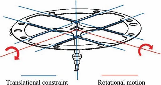
Fig. 2 Schematic diagram of rotational pointing mechanism.
2.2. Configuration of fast steering mirror
The assembled FSM incorporates a planar flexure comprising eight symmetric beam flexures, an axial flexure, two pairs of VCAs,four non-contact position sensing eddy current sensors,mirror support,mirror and a housing.Fig.3 demonstrates the detailed assembly of the designed FSM.
Four eddy current sensors are mounted to the housing and are separated from the flexure mechanism to monitor the realtime position of the mirror.Planar flexure and axial flexure are arranged in the orthogonal axis and are affixed to the housing.The mirror is attached to the mirror support that is attached to the planar flexure. The magnet of the VCA is affixed to the housing and the coil moves the mechanism. VCAs are robust against disturbances and are adopted in many applications for their commending resolution,force output and response.32The motion of the actuator pair is articulated linearly in the opposite direction to develop a moment in the flexure.This linear actuation produces a moment about the RPM axis. Symmetric combination of blade flexures restricts the undesired in-plane rotational and translational compliance while axial flexure further limits the out of plane translational compliance of the RPM.The mass or shear center of the mirror lies at the intersection of the axial flexure and geometric center of the planar flexure.This coincidence is essential to mitigate surface distortions that can arise by gravity.33
3. Characterization of compliance
Theoretical analysis for the compliance of RPM is critical to establish a desired kinematic requirement.Meeting the desired number of DOF about in-plane rotational axes is the prime design objective while constraining the remaining DOF. It has been kept in mind to have greater compliance along DOF direction than along the DOC direction.34This compliance scenario is in direct contradiction to rigid-body counterparts as in compliant mechanism compliance in DOC direction cannot be zero neither infinite in DOF direction. Such a compliance characteristic is prone to generate parasitic motions and cross-axis coupling that needs to be minimized.
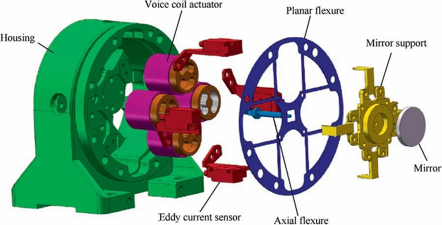
Fig. 3 Exploded view of fast steering mirror assembly.
Design parameters and material properties strongly influence the compliance characteristics. The compliance matrix of the mechanism is developed based on material and geometric properties. The dimension parameters of planar flexure are shown in Fig. 4. Planar flexure is discretized into eight beam flexures numbered from 1 to 8 for devising overall compliance matrix. The beam flexures are assembled symmetrically at a distance d. The overall compliance matrix of the RPM is derived based on the bottom-up approach. Elements of the compliance matrix are explicit functions of material properties and flexure parameters. Appropriate coordinate transformations of twists and wrenches35are taken for systematic characterization of flexures connectivity. In the compliance matrix(Eq.(24))factors are indicated in Cijformat,wherein,the first subscript represents deflection about a specific DOF,while the second subscript indicates the load producing the corresponding deformation.36
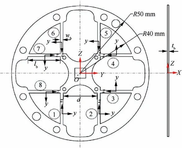
Fig. 4 Configuration of planar flexure.
The four layouts as shown in Fig. 5 are assessed for the DOF by assessing principal diagonal elements of the compliance matrix in MATLAB. All the layouts take their inception from the graphical approach as outlined in the former section.The external periphery of the four configurations indicates a constraint ground while the functional stage is a depiction of the mirror. The layouts are sequenced in terms of constraints they possess. The layout 1 exhibits exact constraint, allowing two in-plane rotations but is not symmetric. The layout 2 is slightly over constraint and is advantageous for desired symmetric rotational motions.The layout 3 being highly over constraint is expected to achieve low compliance and high weight penalty. The layout 4 although does not meet constraint requirement specified in the graphical approach as being under constrained for rotational motion normal to planar flexure axis, is included here for comparison. Elements other than the principal diagonal elements of the overall compliance matrix are to be ignored since in most cases their magnitude is zero and depicts the parasitic error.The analytic compliance evaluation for the four layouts involves a permissible approximation for axial constraint. As in analytical modeling, axial constraint is taken to a circular cross-section flexure. Such an approximation in analytical modeling is permissible since circular cross-section axial flexure is convenient to be modeled analytically and allows five DOF and only one axial constraint37To increase the in-plane rotational compliance, in actual prototype and FEA model, axial flexure geometry involves spherical flexures and a circular cross-section flexure rod.
The coordinate transformation of screws (twists and wrenches)14has been utilized for systematic connection of beam flexures and axial flexure. Flexure mechanisms are designed to obtain desired motion under prescribed loading conditions. The subsequent sections explain the analytical modeling of beam and axial flexures and then the parallel integration leads to the development of entire compliance of the mechanism mathematically in a matrix form. The procedure is described below.
3.1. Analytic model of beam flexure
A beam flexure with a rectangular cross-section is shown in Fig. 6. The dimensional parameters of beam flexure are lb, tband wbrepresenting the length, thickness and width of beam flexure respectively.
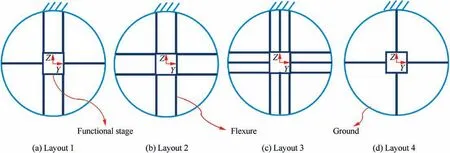
Fig. 5 Configuration of planar flexure layouts.
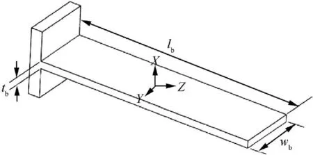
Fig. 6 A beam flexure with coordinate system.
The center of beam flexure points the location of the local coordinate frame and it is desired to obtain the compliance characteristics at the beam end. The material of the planar and axial flexure is steel 05Cr17Ni4Cu4Nb (equivalent to American 17-4PH steel)38with elastic modulus E=213 GPa, yield strength ys=1000 MPa, poisson ratio ν=0.3 and density ρ=7780 kg/m3. Material’s high ys/E ratio makes it a good choice for precision engineering applications. We denote the deformation by a general twist Tˆ=(θ; δ)=(θx,θy, θz; δx, δy, δz) and a wrench Wˆ=(M; F)=(Mx, My, Mz;Fx, Fy, Fz) accounts for the force vector. The column vectors form the depiction of the twist and wrench.The flexure’s material and geometric parameters now play the central role in deriving the mapping step from wrench to twist vectors. The correlation between loading wrench and deformation twist is highlighted in Eq. (1). Since the deformation for precision equipment is in the range of few milliradians it is appropriate to follow linear theory of elasticity. Hence, the Eq. (1)describes the relationship between Tˆ, indicating the twist vector and Wˆ, representing the wrench vector, so mathematically the correlation becomes.

The matrices [C] and [K] are of order 6×6 and formulate the compliance and stiffness respectively. The compliance matrix [Cb] for the beam flexure, which as derived in Ref. 14 and is determined by the material property and geometric parameters of the flexure mechanism shown in Eq. (2),
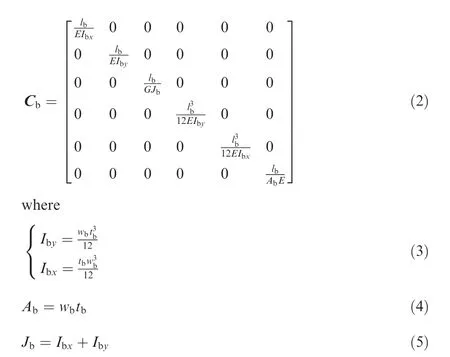
The E and G represent the elastic and shear modulus respectively. The Jbrepresents the torsion constant. From Eq. (2) it is not hard to see that the five independent design parameters (E, G, tb, wb, lb) determine beam compliance [Cb].
3.2. Analytic model of axial flexure
Based on the assumption highlighted in the previous section,an axial flexure of length laand a circular cross-section of radius rais formulated analytically in the current section.The center of axial flexure points the location of local coordinate frame and its compliance matrix [Ca]is written as in Ref.14
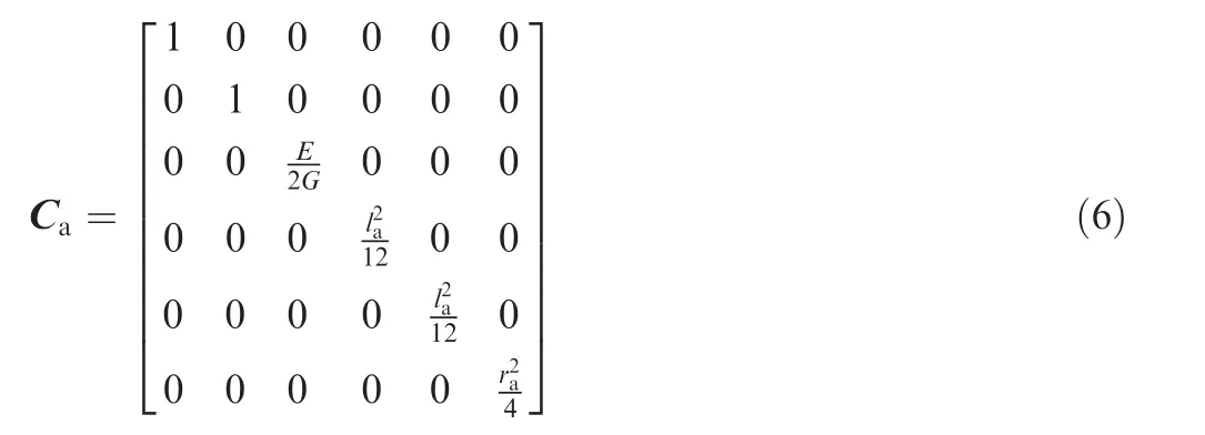
3.3. Combination of beam and axial flexure
A parallel summation of eight beam flexures and an axial flexure structures the RPM. The parallel combination so developed enables estimation of the deflection of the mirror and is the superimposition of the individual flexure elements deformation. The overall compliance of the RPM is so obtained that the compliance of the individual flexures is first transformed in the identical coordinate system and then integrated. Eqs. (2) and (6) represent the compliance matrices for beam and axial flexure respectively in the local coordinate system. Hence, the coordinate transformation becomes necessary for calculating the overall compliance matrix [C] of the mechanism in the global coordinate system as in Eq. (7)

The matrix [Adbi] and [Ada] points the coordinate transformation from ith beam flexure and axial flexure to the mirror respectively. The matrix [Adb,a] is an adjoint transformation matrix of order 6×6 and is marked as

In Eq. (8) the skew-symmetric matrix [D]defines the translation.The adjoint transformation matrix inversion is depicted in Eq. (9)

where here the superscript ‘‘T” portrays the matrix transpose.[R] is 3×3 rotation matrix and can be written as

Investigation of the overall compliance/stiffness of the RPM requires the evaluation of the transformation matrix where, the coordinate transformation from local coordinate system to the global one takes place. For beam flexures 1 and 2 translating the coordinate along the Z-axis fulfills the coordinate transformation
So, we have
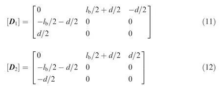
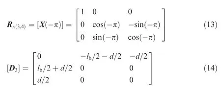
For beam flexures 3 and 4 a rotation of-π about the X-axis and translating the coordinate along the Z-axis achieves the coordinate transformation. Hence,

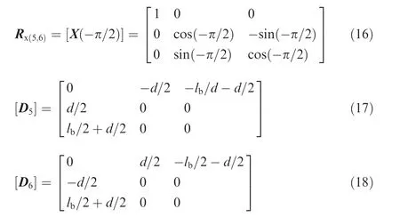
For beam flexures 5 and 6 a rotation of angle -π/2 about the X-axis and translating the coordinate along the Z-axis attains the coordinate transformation. So,
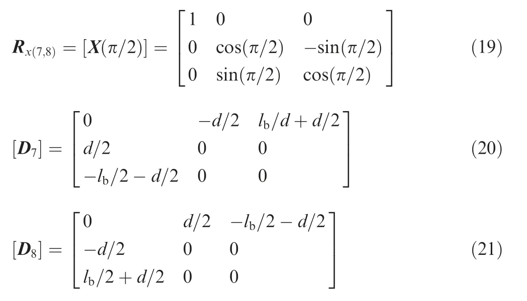
For beam flexures 7 and 8 a rotation of angle π/2 about the X-axis and translating the coordinate along the Z-axis meets the coordinate transformation. Wherein,
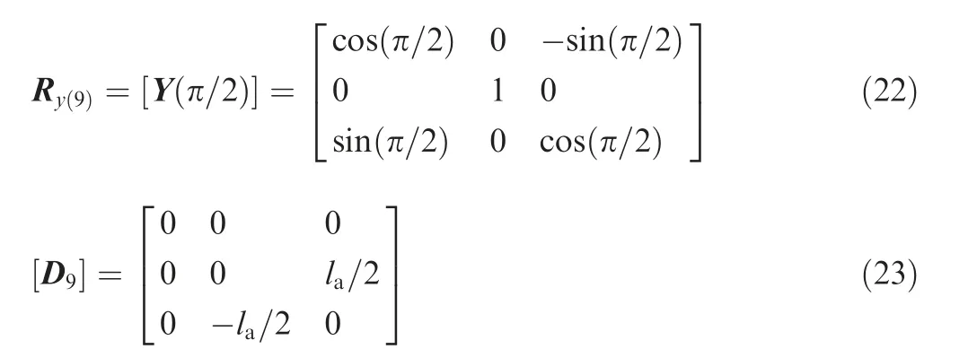
For axial flexure a rotation of angle π/2 about the Y-axis and translating the coordinate along the Z-axis completes the coordinate transformation. Whereas,
Substituting the above transformation matrices, we obtain the overall compliance matrix as mentioned in Eq. (7)
And the compliance matrix is computed as
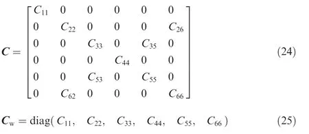
The symmetry of the designed mechanism enables the evaluation of same rotational compliance about Y and Z axes,shown mathematically in Eq. (26) as

This illustrates the same rotational stiffness about Y and Z axes. Eq. (25) represents the diagonal [Cw] of compliance matrix [C] wherein C22and C33are the desired compliances about Y and Z axes and are intended to be maximized while keeping remaining compliances to be minimum. Values of C22and C33represent in-plane rotational DOF.
The compliance matrix evaluation provides preliminary design guidelines for the mechanism. Analyzing the elements of principal diagonal in the compliance matrix37reveals the requirements for the DOF conveniently.
Fig. 7 shows the plot of analytically evaluated compliances at parameters nominal values of lb=23 mm, wb=2.0 mm,tb=0.5 mm, la=37.0 mm, d=34.0 mm and ra=1.75 mm.The in-plane rotational compliances about Y and Z axes are C22and C33respectively. Layout 1 has better in-plane rotational compliance than layout 2 but is not feasible as being less constrained for axial rotation and non-symmetric translational constraints. Layout 3 has the benefit of maximum DOC but has a shortcoming of reduced DOF than layout 2. Additionally, layout 3 if selected will pose a mass penalty in having additional beam flexures.Layout 4 although possess maximum rotational compliance but is rejected in having maximum rotational compliance about X-axis.
The theoretical formulation verifies the layout’s constraint and motion characteristics as predicted earlier. So, based on the result of theoretical compliance,it is optimal to choose layout 2 for the sensitivity analysis and the physical prototype manufacturing for experimental testing.
4. Sensitivity analysis
4.1. In-plane rotational compliance sensitivity
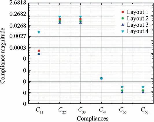
Fig. 7 Compliance characterization for four layouts.
This section elaborates on the sensitivity analysis of desired inplane rotational compliance with the variation of geometric parameters of flexure. The sensitivity analysis of the RPM is accomplished based on the derivation of the overall mechanism compliance matrix in Section 3.The effect of deterministic design parameters on the desired compliance C22and C33is assessed in detail. Fig. 8 shows the plot of analytically evaluated in-plane rotational compliance C22and C33about Y and Z axes wherein, the design parameters are changed as mentioned. The horizontal axis is normalized for each parameter, facilitating comparison. It is pertinent to highlight here that this geometric parameter variation is performed for one parameter at an instant by keeping the remaining parameters at their nominal values. The normalization of each flexure parameter provides convenience for comparison. The ranges of geometric parameters that are considered for sensitivity analysis are depicted in the legend of figure.
From Fig. 8 it is evident that wbis the dimensional parameter exerting maximum sensitivity on the desired rotational compliance and demands its tolerance to be carefully determined. The radius of the axial flexure rahas a relatively weak sensitivity to the mechanism compliance but a suitable value has to be chosen for prototype manufacturing. The thickness of beam flexure has shown sensitivity in the lower values.Variation of flexure mechanism parameters has provided a design space for achieving desired mobility in two in-plane rotational degrees of freedom at initial design levels. Hence at this level parametric exploration has enabled a design guideline without resorting to FEA and experimental tests.
4.2. Parasitic error of instant rotation center
The entity C33refers to the angular deformation θzstimulated from loading Mzand C53is the parasitic translational deformation δy. Here on the X-axis, we can highlight the instant rotation center position as

Meanwhile,the point(0,0,0)is the nominal instant center,lying at the geometric center of planar flexure and intersection of axial flexure.It is worthy to find the position of flexure concerning the mirror.The parasitic error Δrxof the instant center aids in this respect and is the same as the instant rotation center position calculated as in Eq. (28)
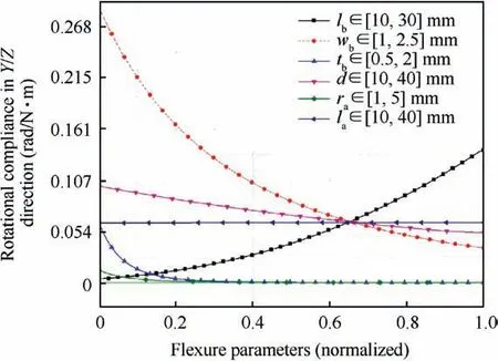
Fig. 8 Compliance of mechanism about Y and Z axis as obtained using Eq. (7) when one parameter is varied keeping remaining parameters at their nominal values.
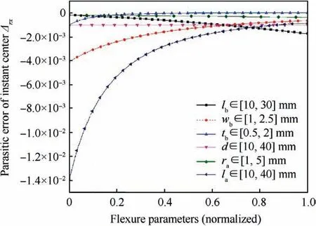
Fig.9 Parasitic error of instant rotation center as obtained using Eq. (28) when one parameter is varied keeping the remaining parameters at their nominal values.

For the forces Fyand Fz, Eq. (29) characterizes the instant rotation center as

From Eq. (29) it is evident that a force applied laterally to Y-axis will cause mirror rotation about an axis parallel to Zaxis and coincident with the instant rotation center. The same tilt scenario is achieved about Y-axis by a lateral force on Zaxis. The translational compliances along Y and Z axis are the same due to geometric symmetry calculated as

From these results, it is convenient to predict that rotational stiffness about the Y and Z axis is the same. This will be proven in our later Section 5 from FEA and experimentation.
Fig. 9 highlights the variation of design parameters specified against Δrx. The horizontal axis is normalized for each parameter, facilitating comparison. The length of the axial flexure lathat was shown to be ineffective to the sensitivity of in-plane rotational compliance in Fig. 8 is found to most sensitive parameter to the parasitic error shown in Fig. 9.The parasitic error decreases nonlinearly as the length of the axial rod increases.The exploration of dimensional space with optimization routines can be made convenient by resorting to both Figs. 8 and 9.
5. Experimental verification
5.1. Evaluation of in-plane rotational stiffness
This section describes the experimental tests and numerical simulation of the designed mechanism for investigating stiffness characteristics. The three-dimensional model of the RPM is established utilizing SOLIDWORKS V.17.0, then it is input into ANSYS v.15.0 for stiffness analysis with geometric non-linearity. To fulfill the requirement of detailed investigation, the planar flexure and axial flexure are finely meshed and comprise 23838 nodes and 20119 elements. Fig. 10 shows the assembled prototype for investigating stiffness characteristics of both in-plan rotational axes.
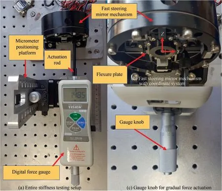
Fig. 10 Proof of concept prototype.
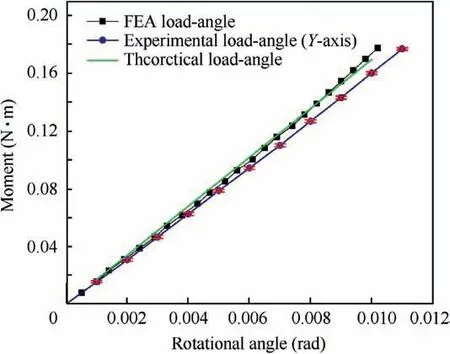
Fig. 11 Stiffness test (about Y-axis) of 2-DOF rotational pointing mechanism integrated with a fast steering mirror.
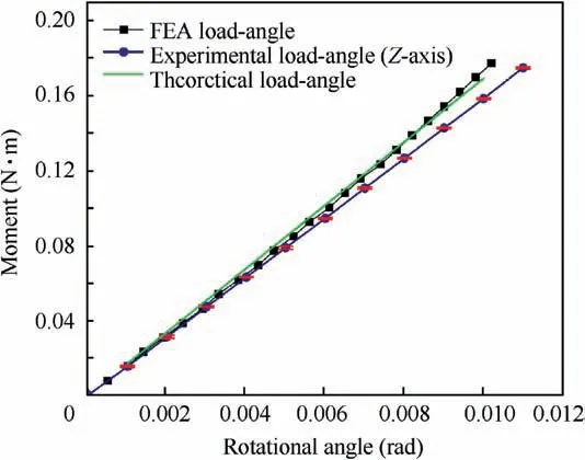
Fig. 12 Stiffness test (about Z-axis) of 2-DOF rotational pointing mechanism integrated with a fast steering mirror.
Planar and axial flexure is manufactured by a piece of steel 05Cr17Ni4Cu4Nb material using wire electrical discharge machining on CHARMILLES ROBOFIL380, Switzerland.The mechanism is manually actuated utilizing gauge knob mounted on a micro-positioning platform. The digital force gauge (DS-20N, Resolution of 0.01 N) is first mounted on the Y-axis and later Z-axis to measure the stiffness characteristics for these axes. The digital force gauge is mounted for measuring the force.The digital force gauge knob is gradually rotated to monitor the force increase from the gauge display.The axial displacement is monitored at gradual intervals and is determined by multiplying the least count of the gauge with the interval increment.The vertical displacement of the digital force gauge is precisely applied to the actuation midpoint for the first Y-axis and then on the Z-axis. The vertical slender knob of the force gauge yields rotation about an axis under consideration. The product of force magnitude and offset distance between centers of two actuators which is equal to 40 mm quantifies the moment. Force is applied gradually up to 5.0 N, thus yielding the mechanism an angular ravel of±10 mrad. The measurement is repeated three times for both axes.
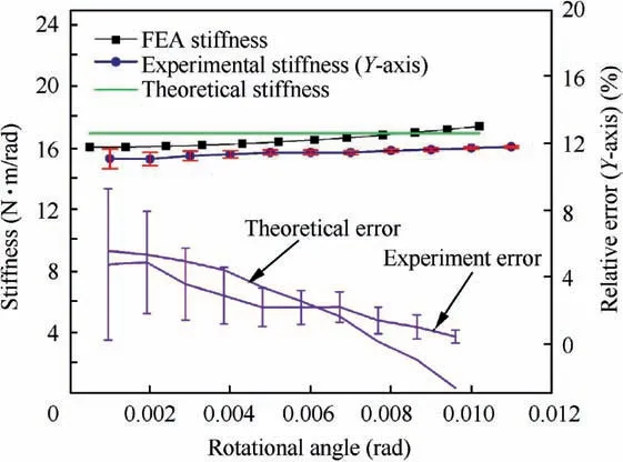
Fig. 13 Stiffness test (about Y-axis) of 2-DOF rotational pointing mechanism integrated with a fast steering mirror.
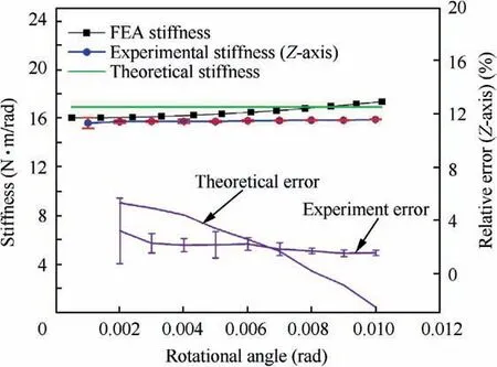
Fig. 14 Stiffness test (about Z-axis) of 2-DOF rotational pointing mechanism integrated with a fast steering mirror.
From the Figs.11 and 12,it is evident that the output angular travel increases linearly with the increasing moment,showing the mechanism’s good linearity. It is worth noting that small error bars dominate the entire spectrum of measurement and reveal diminished uncertainty of measured data.This confirms a high repeatability of experimental data.The theoretical stiffness agrees with the FEA stiffness wherein, the theoretical error ΔT=|KT-KFEA|/KFEAis less than 5.5%.The theoretical error is expected from the simplification taken in the modeling of the axial flexure. Also, the theoretical stiffness can be reduced when spherical flexures are incorporated in the modeling of axial flexure thereby, resulting in a slight increase of inplane rotational compliance. It is further realized that data points from both FEA and experiment revel good stiffness linearity for angular travel up to ±10mrad for both axes as in Figs. 13 and 14. The experimental error ΔE=|KE-KFEA|/KFEAis within an accepted 5% and 3% average error for the Y and Z axis respectively. Such a minor error is envisaged to be from material non-linearity,assembly/manufacturing errors or measurement errors. If the stiffness variation is large a robust control system has to be incorporated making the design of the control system more complex.
5.2. Stress developed in flexure
Stress developed during the flexure deflection is another important consideration that needs to be accounted for deciding the maximum angular rotation by keeping stress levels within acceptable safety bounds. In this context based on FEA, the von Mises stress in planar and axial flexure is demonstrated against angular travel in Fig. 15.
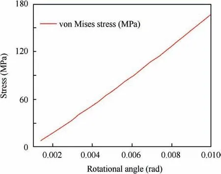
Fig. 15 Variation of von Mises stress over rotational angle in planar and axial flexure.
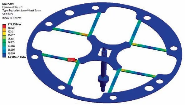
Fig.16 Planar and axial flexure von Mises stress (MPa).
The stress level approaches to 171 MPa when the angular travel reaches ±10 mrad as shown in Fig. 16. This stress level is well below the material’s yield strength. In the experimental setup plastic deformation of flexure mechanism is prevented in keeping the digital force gauge up to 5.0 N, so as the FEA verifies.
5.3. Comparison with other pointing mechanisms
To make a comparison with other pointing mechanisms, the volume efficiency39is considered as a reference performance index. The index determines the compactness of the pointing mechanism for the intended travel range and a large index value is an obvious desirable characteristic.
As shown in Table 1, the proposed RPM has achieved relatively large volume efficiency hence; it is more compact for the desired travel range in comparison with other pointing mechanisms.
6. Conclusion
The conceptual design of a novel pointing mechanism is realized to be critical in the precision engineering domain. The design methodology in its conception for two in-plane rotations leads to design a novel and compact RPM. Analytical compliance calculations for four distinct layouts expose the freedom and constraint scenario at the initial design level.The layout with the best in-plane rotational compliance and maximum constraint for the remaining DOF validates the design conceptualized. Compliance sensitivity to mechanism dimension parameters and parasitic error of the instant rotation center opens up solution space before carrying FEA and experimentation.Further, suitable design parameters can only be selected by simultaneous assessment of both compliance sensitivity and parasitic error of instant rotation center. Since a particular parameter that may be insensitive to desired rotational compliance can impart substantial impact on the parasitic error as found to be the lain this research. The parameters that are found to be more sensitive to desired compliance demand stringent tolerance requirements. Theoretical,numerical analysis and experiments have explicitly evaluated stiffness for both in-plane rotational axes. Further inference is revealed as:
1) The rotational stiffness over the desired angular travel is found to be linear for both in-plane rotational axes.The theoretical error ΔT is less than 5.5%. The theoretical error is expected from the simplification taken in the modeling of the axial flexure. The experimental error defined as ΔE is found to be 5% and 3% for the Y and Z axis respectively. Such a minor error is envisaged to be from the reasons mentioned in the Section 5.
2) The mechanism has achieved a high safety level over the intended angular travel since the stress developed is well below the material’s yield limit.In short,this work is an apt demonstration of design guidance for the mechanical design of a novel high precision pointing mechanism from conceptualization to its validation.
3) The stiffness variation is within acceptable error range;the control system for this precision mechanism will be convenient to design and is sure to avoid the complexity in handling functional requirements.In the future,compliance of the axial flexure might be estimated incorporating compliance of the spherical flexure. Moreover, asimplified trajectory tracking control strategy based on stiffness linearity of the RPM can be developed for subsequent testing in 1DOF and 2DOF.

Table 1 Performance comparison of typical pointing mechanisms.
Acknowledgements
This work was co-supported by the National Natural Science Foundation of China (No.91748205 and 51675032) and the Fundamental Research Funds for the Central Universities(No.YWF-18-BJ-Y-34 and YWF-18-BJ-J-23) of China.
 CHINESE JOURNAL OF AERONAUTICS2020年12期
- CHINESE JOURNAL OF AERONAUTICS的其它文章
- Design and experimental study of a new flapping wing rotor micro aerial vehicle
- CFD/CSD-based flutter prediction method for experimental models in a transonic wind tunnel with porous wall
- Prediction of pilot workload in helicopter landing after one engine failure
- Study of riblet drag reduction for an infinite span wing with different sweep angles
- Modulation of driving signals in flow control over an airfoil with synthetic jet
- Strong interactions of incident shock wave with boundary layer along compression corner
