Modulation of driving signals in flow control over an airfoil with synthetic jet
Zhiyong LIU, Zhenbing LUO, Qing LIU, Yn ZHOU
a College of Aerospace Science and Engineering, National University of Defense Technology, Changsha 410073, China b China Aerodynamics Research and Development Center, Mianyang 621000, China
KEYWORDS Airfoil;Flow control;Injection angle;Modulation;Momentum coefficient;Synthetic jet
Abstract A new skill of modulating driving signals of a synthetic jet with low frequency is introduced to enhance the control authority. Based on dynamic mesh technique, the effect of flow control over a NACA0015 airfoil with a Synthetic Jet Actuator(SJA)has been investigated.The SJA is located at x/c=10%,and two jet injection angles of 90°and 30°have been considered.Flow structures indicate that modulation with low frequency can reduce the dissipation rate of vortices after they shed off the surface.Thus aerodynamic performance of the airfoil could be improved.For the injection angle of 90°, modulation can increase the control authority of the SJA. Compared to the unmodulated case, increment of lift-to-drag ratio is up to 15%. The modulating frequency corresponding to the largest increment is F+M ≈1. For the injection angle of 30°, improvement of aerodynamic forces positively relates to momentum coefficient of the SJA. Due to the decrease of effective momentum, modulation degrades the effect of flow control. The opposite responses to modulation are believed to have a relationship with the variation of primary control mechanism.When jet injection angle varies from 90° to 30°, the primary mechanism changes from the interaction of vortices and waves to the direct momentum addition.The skill of modulation of driving signals is very useful for applications of SJA.
1. Introduction
Active Flow Control (AFC) plays an ever-growing part in aerodynamic research.1Along with increasingly strict constraints to aviation industry, advanced aerodynamic performance is required urgently. However, conventional aerodynamic designs seem to be close to its ceiling. Researchers turn to some innovative techniques and hope that the limiting ceiling will be broken.AFC is one of the most promising candidates and has been involved in a large number of investigations.2-4Among various AFC techniques, synthetic jet has attracted much attention in last decades for its simplicity (no plumbing system and easy maintenance), fast response, light weight and compact design.
The effectiveness of synthetic jet has been studied by many researchers. Gilarranz et al.5,6experimentally confirmed that synthetic jet delayed the onset of stall.An 80%increase in the maximum lift coefficient was achieved. You and Moin7performed large-eddy simulations to evaluate the effectiveness of synthetic jets and obtained similar results. Amitay et al.8demonstrated the control authority of synthetic jets on relatively thick airfoils. Taylor and Amitay9confirmed the potential of controlling dynamic stall vortex. Using synthetic jets,the hysteresis of loading could be eliminated. Zhang et al.10used synthetic jet as a circulation control method. Compared to the lift augmentation efficiency of 12.1 in the case with steady blowing, a much higher value of 114 with synthetic jet was reported. A series of wind tunnel experiments conducted by Seifert et al.11-14showed that, to suppress flow separation,the amount of momentum required by periodic excitation is one or two orders of magnitude less than that of steady blowing.
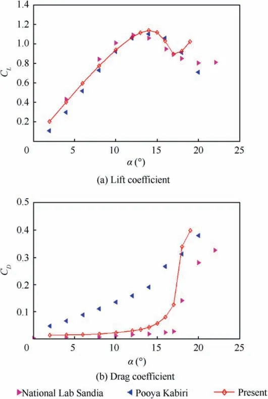
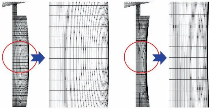
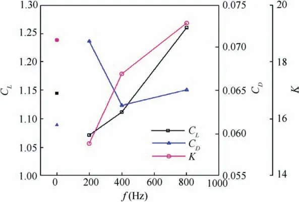
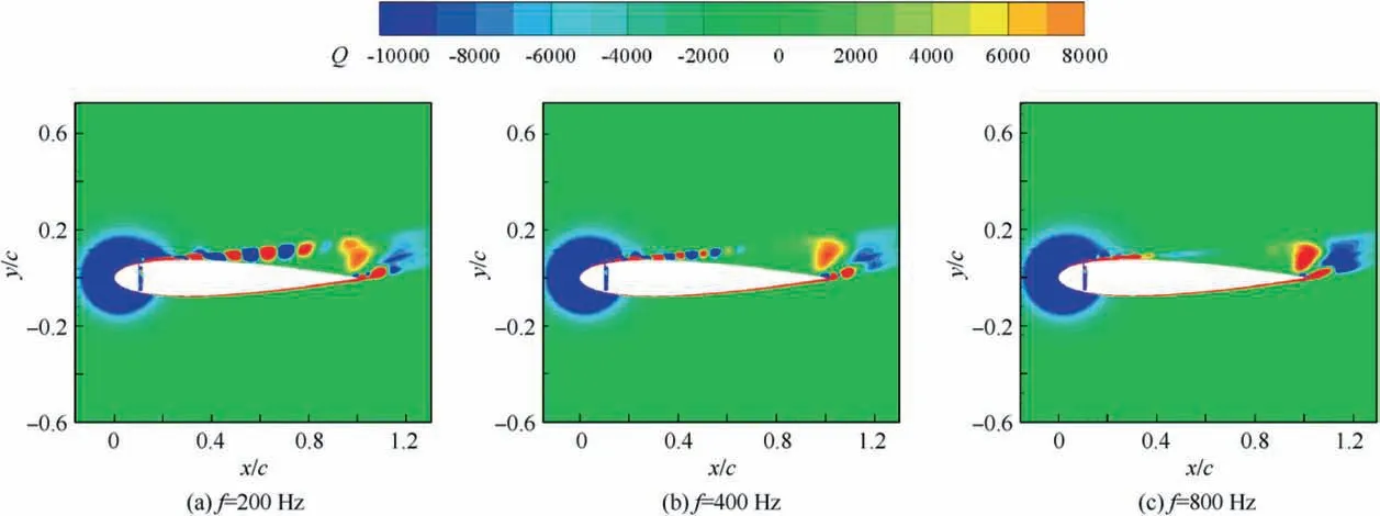
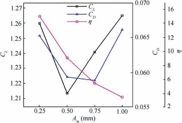
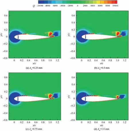
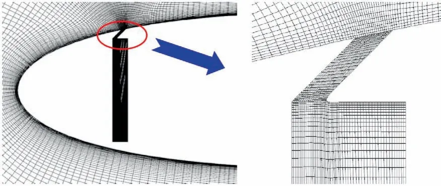
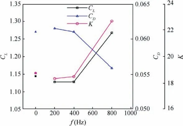
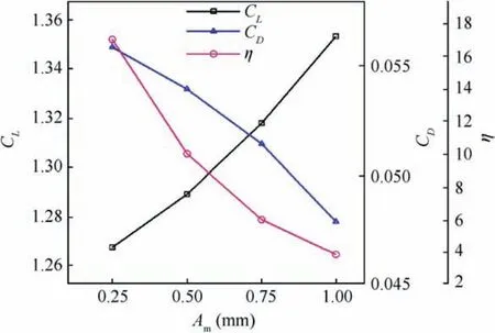
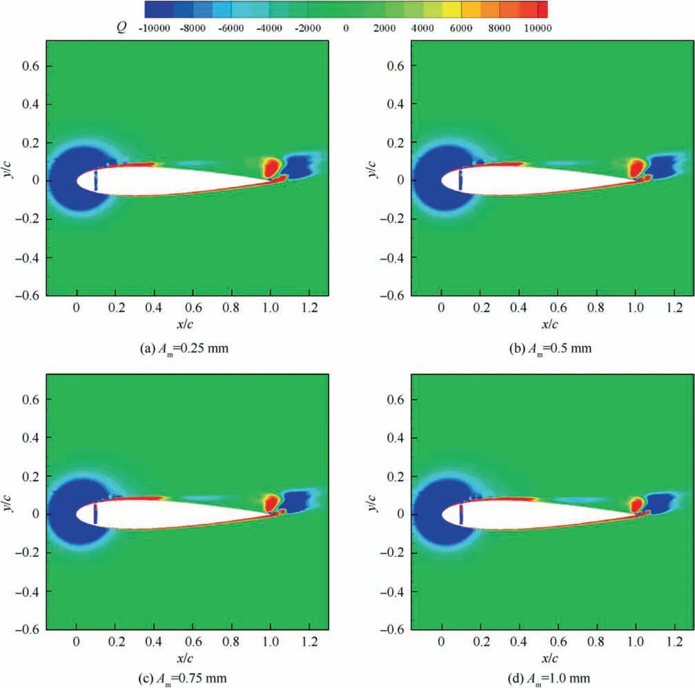
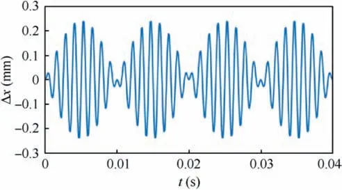
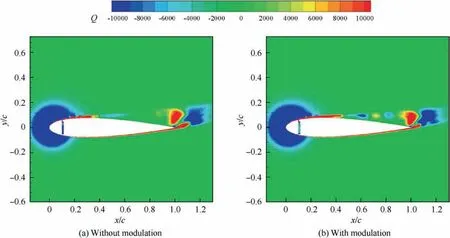
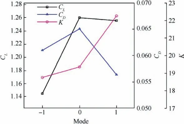
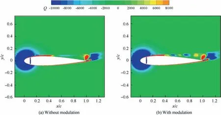
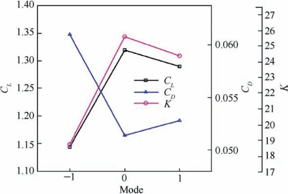
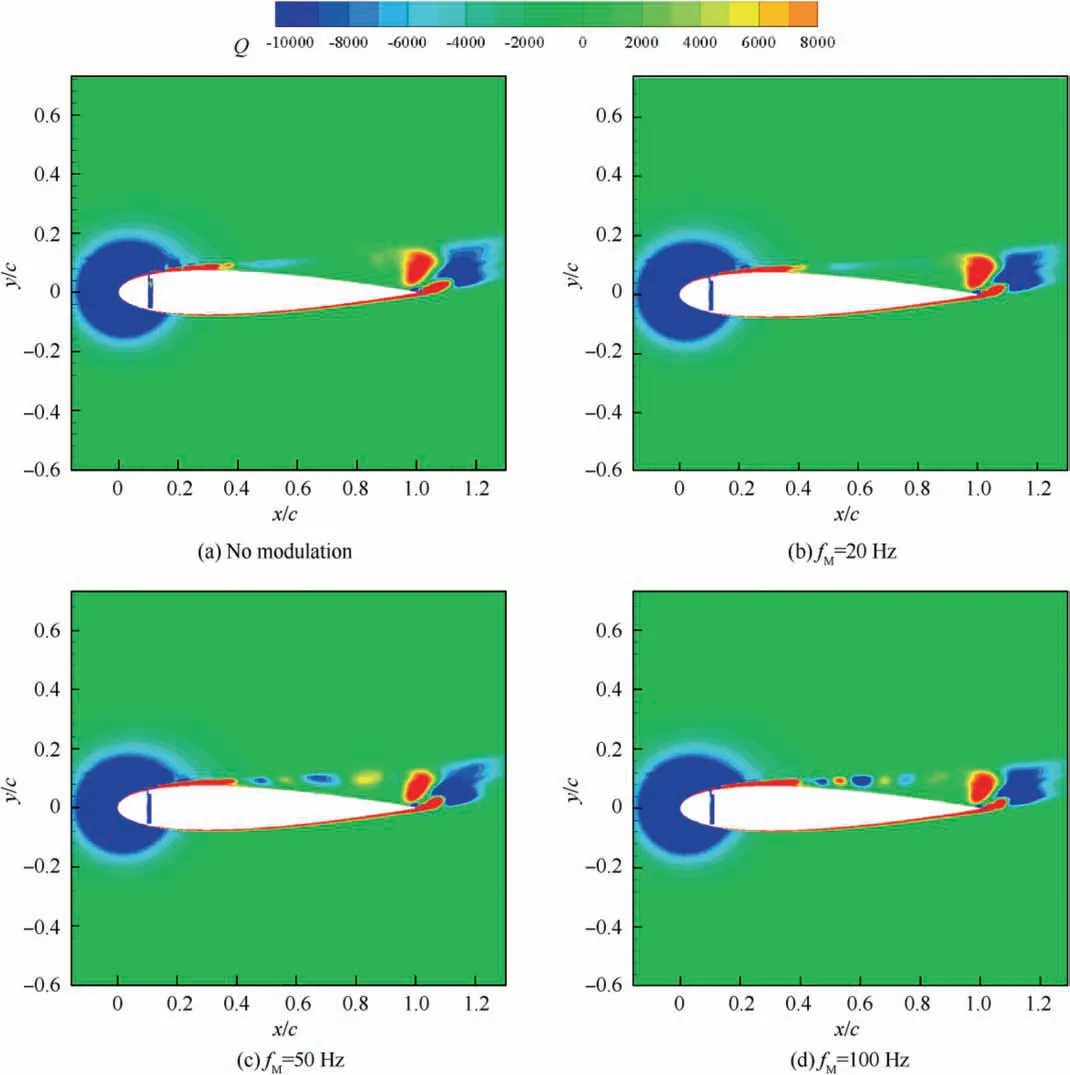
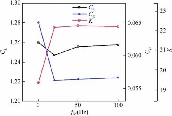
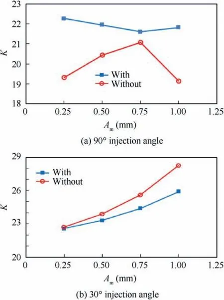
Investigations of control parameters of synthetic jets have also been conducted deeply and extensively. Experimental results derived from Seifert et al.14showed that optimal reduced frequency was in the range of 0.5 Due to the curved surface of airfoils,investigations of excitation location usually twisted the influence of jet injection angle (or excitation angle). Hsiao et al.18observed a dramatic lift decrease as the excitation location moved from x/c=1.25% to x/c=13.25% where no lift enhancement could be obtained.In this process,the jet injection angle altered from almost 160° to approximate 100°. Due to the large post-stall angles of attack, separation occurred very close to the leading edge. It resulted in that the latter excitation location was far away from the separation point and completely at circumfluence region. A wrong impression that jet injection angle is inessential may be made. Zhao et al.19showed an opposite viewpoint based on their experimental results. When momentum coefficient was small, a large jet injection angle was effective, whereas a small injection angle was effective for large momentum coefficient.Greenblatt and Wygnanski15suggested that the effects of location and orientation should be evaluated independently. For a piezoelectric Synthetic Jet Actuator (SJA), there is a coupling between excitation frequency and jet intensity. It is well known that high velocity level can just be achieved at the Helmholtz resonance frequency or the diaphragm’s natural resonance frequency. As excitation frequency departs from these optimum values, jet velocity decreases significantly20. It means that the guideline of F+≈1 mentioned above (from Greenblatt and Wygnanski15) is not satisfied commonly. This problem limits the application of piezoelectric SJA as a flow control technique. Greenblatt21and Melton and LaTunia22proposed to modulate the sinusoidal waveform with a lower frequency.Though the original aim was to investigate the transient process associated with attaching and separating the flow on flaps, the method sheds a light on the path to improve the application of piezoelectric SJA. To investigate the independent impact of jet injection angles and finally improve the control authority of piezoelectric SJA in applications, numerical simulations of flow control over an airfoil have been conducted. Dynamic mesh technique which has the ability of relaxing the physical restrictions of SJA is utilized. Unsteady Reynolds averaged Navier-Stokes equations are employed. By modulating driving signal with a low frequency, enhancement of control effect is explored. The structure of this paper is as follows. The method of simulations as well as the validation is presented in Section 2. Dynamic mesh technique is briefly introduced in this section too. In Section 3, the impact of jet injection angles is studied.Modulations with different injection angles are conducted in Section 4, appended by a brief discussion about control mechanisms. The conclusions are drawn in Section 5. A NACA0015 airfoil which is a paradigm in AFC research has been chosen in this study.Length of the chord is c=0.3 m.A piezoelectric SJA with a cavity is located at x/c=10% (see Fig.1).The cavity has a 1.45 mm wide exit slot,a 3.5 mm high neck,and a 4.4 mm×30 mm room.The right side of the room mimics the diaphragm of the piezoelectric SJA.The axis of the exit slot is vertical to the chordwise direction. It leads to an approximate 78° jet injection angle. Structured mesh with an O-type topology is adopted. Grid lines are clustered around the exit slot and in the boundary layer of the airfoil.The outer border is more than 9c far away from the airfoil. Free stream velocity is 12.5 m/s.Reynolds number based on the chord length and the free stream velocity is about 2.5×10⁵. Wall Y+is approximate 1. The k-ω shear stress transport turbulence model has been employed to calculate the flow fields. No-slip wall for the airfoil and the SJA and pressure far field for the outer border are set as boundary conditions respectively. A second-order central difference scheme and a second-order implicit scheme are chosen respectively for spatial discretization and time advancement. Fig. 1 Computational mesh. Fig. 2 Validation of simulation. Results of lift coefficient CLand drag coefficient CDwithout excitation at different angles of attack α are shown in Fig. 2. For very post-stall angles, cycle-averaged values are acquired. Two sets of data from literature are presented for comparison. It seems that good agreement has been achieved in lift force as well as stall angle (about 14°). Before the stall angle, drag forces derived from the present simulations and National Lab Sandia(adapted from Shahrabi17)are consistent with each other. Though evident discrepancies of drag force are observed after the stall angle,the trends of increase of drag force are the same. The drag force derived from Pooya Kabiri’s experiment23also shows the growing trend but with a larger magnitude.In general,the present simulations are reliable and the numerical method is validated. To simulate the vibrations of the diaphragm,mesh of the cavity should be regenerated after the diaphragm moving to a new position. A smoothing spring method is used to calculate new coordinates of grids. When the diaphragm (right side of the cavity) vibrates, the inner grids are stretched and condensed alternately. This behavior just likes a spring. The topology of the grids does not change with this transformation. As for the mesh out of the cavity, it is invariant. Fig. 3 shows two opposite states of the mesh of the cavity. A sinusoidal function is adopted to describe the motion of the diaphragm. Based on an experimental measurement in advance, movement of the diaphragm follows where x is the abscissa of the grid on the diaphragm, r is the distance from the grid to the center of the diaphragm, R is the radius of the diaphragm, Amis the maximum amplitude,and f is the vibration frequency. When time advances a step,new coordinates of the grids on the diaphragm are calculated firstly by Eq. (1). Then the coordinates of the interior grids are regenerated by the smoothing spring method. For convenience, jet injection angle is defined as the included angle between the chord and the axis of the exit slot. Since the SJA is fixed at x/c=10%, about 12° difference exists between the nominal injection angle and the real injection angle. Two jet injection angles of 90° and 30° are considered.Different frequencies and intensities of the synthetic jet are tested. Two sets of parameters have been investigated. One primarily aims at the influence of excitation frequency,and the other primarily aims at the effect of jet intensity. The range of these parameters covers not only the experimental measurement,but also some extension which may not be realizable for the measured SJA. This does not mean that the parameters are nonphysical. In the future, they would become realizable if some improvement of the SJA has been made. The first set of parameters is presented in Table 1. Fig. 3 Two states of cavity’s mesh. Table 1 Parameters of frequency test. From Eq.(1),the vibration velocity of the diaphragm can be obtained as Considering the relatively low speed, incompressible flow assumption is held. The amplitude of velocity at the exit slot of the cavity in blowing phase can be determined by Here d is the width of the slot. It is easy to find that the three cases in Table 1 have the same value of fAmwhich leads to the same Uj. Momentum coefficient Cμdefined as Fig. 4 Impact of excitation frequency with 90° injection angle. is usually adopted to quantify the intensity of jets.Lower index j corresponds to the jet and ∞corresponds to the free stream.This set of parameters is expected to minimize the impact of jet intensity. Angle of attack is set as 15°which is a post-stall angle.It is believed that synthetic jet can improve aerodynamic performance of airfoils significantly after stall. Results with control such as lift coefficient CL, drag coefficient CDand lift-todrag ratio K of the airfoil are presented in Fig.4.For comparison, the values of uncontrolled case are also plotted at f=0 Hz with solid symbols.It is seen that aerodynamic forces are sensitive to excitation frequency. Lift force as well as liftto-drag ratio increases with increasing frequency. However,it is not beneficial with control until 800 Hz. Drag force becomes bigger when the airfoil is under control, especially with 200 Hz excitation. Aerodynamic forces are integral results of flow field,so different flow structures are expected in the three cases. The second invariant Q of the velocity gradient tensor is utilized to visualize flow structures. It is well known that positive Q denotes vortices. Fig. 5 shows the instantaneous contours of Q. It can be seen that big vortices relate to low excitation frequency.As the frequency increases,vortices become small and dissipate rapidly. Small vortices relating to 800 Hz have a trend to merge when they are attaching on the surface of the airfoil. This merging behavior is thought to be responsible for the increment of lift force.Big vortices relating to low excitation frequency contain more vorticity because of the longer excitation period. Thus the vortices dissipate relatively slowly and remain for a long time. The correspondence from excitation frequency to dissipation rate gives the inspiration of modulating driving signals with low frequency. With modulation,aerodynamic forces are expected to be improved.The modulation will be conducted and discussed in Section 4. Excitation frequency then is fixed at 800 Hz.Influence of jet intensity now is studied with different vibration amplitudes which are Am=0.25, 0.5, 0.75, 1.0 mm. Obviously, jet intensity becomes strong as Amincreases. According to Eqs. (3)and (4), the values of Cμfor these four cases are in a proportion of 1:4:9:16.It is natural to think that momentum addition may play an important role in these cases. For quantity comparison purpose, the conventional airfoil efficiency K=CL/CDis redefined as η=CL/(CD+Cμ). Fig. 5 Instantaneous contours of Q with different frequencies and 90° injection angle. Fig. 6 Impact of jet intensity with 90° injection angle. Results with different jet intensities are presented in Fig.6.Lift coefficient CL, as well as drag coefficient CD, shows a V-shape turn as vibration amplitude increases. The redefined airfoil efficiency η decreases monotonically. Before the jet intensity rises to the level of Am=1.0 mm, lift-to-drag ratio K positively relates to momentum coefficient Cμ.While considering the momentum input, the airfoil efficiency η indicates that control by increasing Cμis inefficient. Instantaneous contours of Q corresponding to the four levels of jet are shown in Fig. 7. It seems that jet intensity mainly impacts the distribution of vortices on the surface rather than off the surface. As the level of jet rises, vortices on the surface move down further. When the amplitude rises to Am=1.0 mm, the vortex standing at the trailing edge becomes small obviously. It means that separation on the aft airfoil is suppressed heavily. However, less separation does not always result in smaller drag. A sudden increase of drag is observed in Fig.6 at Am=1.0 mm.It is supposed that very strong jet blocks the flow around the leading edge. Compared to excitation frequency, momentum coefficient is less important in improving the aerodynamic performance of the airfoil with 90° injection angle. Fig. 7 Instantaneous contours of Q with different amplitudes and 90° injection angle. Fig. 8 Local computational mesh with 30° injection angle. Fig. 9 Impact of excitation frequency with 30° injection angle. In this section,effect of flow control with 30°jet injection angle will be discussed. Fig.8 presents the local configuration of the airfoil with the SJA. A round corner is used to mitigate flow separation in the neck of the cavity.Incoming flow parameters are constant and the control parameters tested above are considered again. Aerodynamic forces with different excitation frequencies are plotted in Fig. 9. For comparison, the values of uncontrolled case are also presented with solid symbols at f=0 Hz. As excitation frequency increases, lift force as well as lift-to-drag ratio increases while drag force decreases. With f=800 Hz,the largest improvement is achieved.The effects of excitation frequency on aerodynamic performance are very similar to those of 90° injection angle. One can conclude that excitation frequency is an important factor in flow control no matter jet injection angle is large or small. Distributions of vortices in these cases are more or less the same to those presented in Fig.5.A little difference is that the vortex standing at the trailing edge becomes small at 800 Hz.It means that effect of flow separation control may relate to the combination of excitation frequency and jet injection angle. The excitation frequency is fixed at 800 Hz once again.Results with different jet intensities are shown in Fig. 10.The control effect is favorable though the airfoil efficiency η shows a monotonic descent. Both increment of lift force and reduction of drag force are enhanced as the vibration amplitude increases.It demonstrates that aerodynamic performance positively relates to momentum coefficient of the SJA. Combining the results of excitation frequencies and jet intensities,one can conclude that,with 30°injection angle,both frequency and intensity of SJA are important in improving the aerodynamic performance of the airfoil. Fig. 10 Impact of jet intensity with 30° injection angle. Fig. 11 shows the instantaneous contours of Q relating to the four levels of jet. Different from the distributions of vortices in Fig. 7, the vortices attaching on the surface in Fig.11 tend to merge into a vortices layer.So the distributions of vortices corresponding to different vibration amplitudes are very like each other. However, two major differences are still observed. As jet intensity increases, the vortices layer extends downstream, and the vortex that stands at the trailing edge becomes small. The former may lead to lift increment and the latter may lead to drag reduction.Both of these variations are favorable to aerodynamic performance and have been confirmed in Fig. 10. Low frequency is employed to modulate the waveform of the driving signals. The high excitation frequency is utilized to maintain good aerodynamic performance, while the low modulating frequency is utilized to alter the distribution of vortices.Modulation is aimed at enhancing the control authority of the SJA. As a matter of fact, 600-800 Hz is the most effective range for the SJA used in the measurement, while the natural instability frequency in the base flow around the airfoil is about 42 Hz which is much lower than the excitation frequency.According to the guideline of F+~1,control at 800 Hz is not very efficient. This has already been confirmed in Fig. 4 by the fact that the increment of lift-to-drag ratio is small.Thus modulation with a low frequency fMis conducted to augment the effectiveness of flow control with the SJA. The motion of the diaphragm is then controlled by Eq.(5).History of the displacement of the diaphragm’s center with f=800 Hz and fM=50 Hz is presented in Fig. 12. Fig. 11 Instantaneous contours of Q with different amplitudes and 30° injection angle. Fig. 12 History of displacement of the diaphragm’s center. Second harmonic is observed obviously in Fig. 12. For the sign of the modulating function makes no sense,the waveform is modulated mainly by a frequency of 100 Hz.For the sake of convenience, the modulation frequency is still noted as 50 Hz.With modulation and 90° injection angle, the case of f=800 Hz and Am=0.25 mm is examined. Instantaneous contours of Q with and without modulation are shown together in Fig. 13. As expected, the vortices still remain after shedding off the surface of the airfoil,although they are weakened as they advect downstream. Moreover, the merging of vortices on the surface is enhanced. It indicates that suction force on the forepart may be augmented. Another favorable change is that the path of the shedding vortices deflects to the surface. This is helpful for the suppression of flow separation at the trailing edge. Pressure on the aft airfoil may be recovered, which results in drag reduction and some lift loss. Aerodynamic forces with and without modulation are presented in Fig.14.The results of no control case are plotted too.The values of mode of-1, 0 and 1 correspond to no control,without modulation and with modulation respectively. It is seen that the variations of lift and drag forces are consistent with the preceding analysis based on flow structures.Opposite effect of pressure variation at the forepart and the rear part of the airfoil results in a negligible loss of lift force. Meanwhile,drag force decreases more than 10%. As a result, the lift-todrag ratio is elevated by 15%.When momentum coefficient of the SJA increases, positive effect brought by modulation decreases until Am=1.0 mm. It demonstrates that the potential of flow control with SJA can be boosted by modulation of driving signals in the condition of large injection angles. Fig. 13 Instantaneous contours of Q with modulation and 90° injection angle. Fig. 14 Aerodynamic forces with modulation and 90° injection angle. A same modulation with fM=50 Hz is conducted to the case of f=800 Hz and Am=0.75 mm with 30° injection angle.Figs. 15 and 16 display the flow structures and aerodynamic forces respectively. Meanings of the values of mode are like the ones mentioned in Section 4.1. Once again low frequency modulation changes the distribution of vortices significantly.However,the effect is negative.Due to the decrease of effective amplitude, the momentum coefficient Cμactually decreases a little with modulation. Compared to the unmodulated case,the modulation leads to a shorter vortices layer attaching to the surface. It means a lift loss and an early separation. As a result, aerodynamic performance of the airfoil deteriorates.As the vibration amplitude increases, negative effect brought by modulation augments. Based on the results without and with modulation, one may conclude that momentum coefficient is predominant to excitation frequency in flow control with small jet injection angles. Fig. 15 Instantaneous contours of Q with modulation and 30° injection angle. Fig. 16 Aerodynamic forces with modulation and 30° injection angle. Another two modulating frequencies of fM=20 Hz and 100 Hz are also tested with the driving signal of f=800 Hz and Am=0.25 mm and with 90° injection angle. Results are shown in Figs. 17 and 18. The values of unmodulated case are plotted at fM=0 Hz.It seems that relatively low modulating frequency like fM=20 Hz does not change the distribution of vortices obviously. However, relatively high modulating frequency like fM=100 Hz decreases the size of vortices and cannot keep vortices chain to the trailing edge completely. Generally, significant reduction of drag force can be achieved with modulation,and only a little loss of lift force is penalized. Thus aerodynamic performance is improved much. Fig. 17 Instantaneous contours of Q with different modulating frequencies. Fig. 18 Comparison of aerodynamic forces with different modulating frequencies. Fig. 19 Comparison of modulation effect with different jet injection angles. Though the differences of control effect among the three modulated cases are small, some tendency can be observed clearly.Both lift force and drag force increase with the increase of modulating frequency. As a result, the variation of lift-todrag ratio is minor. However, the maximum lift-to-drag ratio is achieved at fM=50 Hz though it is less distinct. It should be reminded that this optimal modulating frequency is close to the natural instability frequency in the base flow. Thus the optimum reduced modulating frequency defined in Eq. (6) is≈1. Reviewing the results of flow control with different excitation frequencies, jet intensities and injection angles, one can conclude that both frequency and momentum coefficient of synthetic jet can influence the control effect. However, with different injection angles, the importance of the two factors is different.With large injection angles,frequency is more efficient than momentum coefficient, while with small injection angles, both frequency and momentum coefficient are important to aerodynamic performance. Distribution of vortices is altered obviously by modulation with low frequency.However,this alteration is not always beneficial for aerodynamic performance. With large injection angles, the aerodynamic performance can be improved significantly,while with small injection angles,modulation will deteriorate the aerodynamic performance (see Fig. 19). The opposite effects of modulation demonstrate that different control mechanisms are predominant with different injection angles. Ref. 24 generalized six types of flow control mechanisms. Two of them called interaction of vortices and waves and direct momentum addition are supposed to be responsible for the modulated cases of 90°and 30°injection angles respectively. For large injection angles, the interaction of vortices and waves mechanism is enhanced because of the remaining vortices that are introduced by low frequency modulation.So the control authority is augmented. For small injection angles,the direct momentum addition mechanism is weakened due to the decrease of effective momentum. Thus the control effect degrades. This explanation is consistent with the experimental results of Zhao et al.19 Based on dynamic mesh technique, the influence of jet injection angle in flow control over a NACA0015 airfoil has been investigated. A new skill of waveform modulation with low frequency is introduced to enhance the control authority of piezoelectric SJA. Simulation results indicate that low frequency modulation can enhance the control effect when jet injection angle is large.Optimum control will be achieved with modulating frequency of F+M≈1. However, it degrades the control effect when jet injection angle is small. A discussion has been made to explain these opposite behaviors. For large jet injection angles, the main control mechanism tends to the interaction of vortices and waves.To this mechanism,excitation frequency is more effective than momentum coefficient. Instantaneous contours of Q show that, with modulation, vortices that shed off the surface dissipate slowly. Therefore the interaction of vortices and waves is enhanced and the aerodynamic performance is improved. For small jet injection angles, the main control mechanism turns into the direct momentum addition. Under this mechanism,the aerodynamic performance is positively related to the momentum coefficient of synthetic jet. Due to the decrease of effective amplitude,a momentum loss exists and the control effect is degraded with modulation. For a real piezoelectric SJA, the maximum velocity is bounded to a narrow bandwidth of excitation frequency. The frequency is usually one order of magnitude higher than the instability frequencies in base flows. Thus the most effective flow control cannot be achieved. It limits the applications of piezoelectric SJA. The introduced skill of low frequency modulation can relax the limitation significantly. In future work,experiments will be done to confirm this ability and to validate the optimum modulating frequency. Acknowledgements This study was supported by the National Natural Science Foundation of China (Nos.: 11872374 and 11602299).2. Method of simulations
2.1. Computational method and validation

2.2. Dynamic mesh technique

3. Results with different jet injection angles
3.1. Jet injection angle of 90°


3.2. Jet injection angle of 30°
4. Low frequency modulation
4.1. Modulation with 90° injection angle

4.2. Modulation with 30° injection angle
4.3. Effect of modulating frequency

4.4. Discussion about control mechanisms
5. Conclusions
 CHINESE JOURNAL OF AERONAUTICS2020年12期
- CHINESE JOURNAL OF AERONAUTICS的其它文章
- Design and experimental study of a new flapping wing rotor micro aerial vehicle
- CFD/CSD-based flutter prediction method for experimental models in a transonic wind tunnel with porous wall
- Prediction of pilot workload in helicopter landing after one engine failure
- Study of riblet drag reduction for an infinite span wing with different sweep angles
- Strong interactions of incident shock wave with boundary layer along compression corner
- An efficient regulation approach for tomographic reconstruction in combustion diagnostics based on TDLAS method
