Reliability evaluation of avionics system with imperfect fault coverage and propagated failure mechanisms
Ying CHEN, Song YANG, Rui KANG
Science and Technology on Reliability and Environmental Engineering Laboratory, Beihang University, Beijing 100083, China
KEYWORDS Acceleration;Binary Decision Diagram (BDD);Failure mechanism;Imperfect Fault Coverage;Multi-layer system;Reliability evaluation
Abstract Fault tolerance designs are essential techniques for systems that require high levels of reliability, such as aircraft or spacecraft control system. Imperfect Fault Coverage (IFC) may lead to the failure of a system or subsystem even with adequate redundancy. Previous studies of IFC mostly concentrated on evaluating Coverage Factor (CF), whereas the system failure behaviors with IFC have rarely been involved. Failures that occur in low-layer may be covered by highlayer. However, if the coverage is imperfect, uncovered failure will have functional and physical impact on the system behavior. In this thesis, the failure behavior and reliability of IFC of multi-layer systems are studied and a Binary Decision Diagram (BDD)-based modeling and simulation method are proposed to evaluate system reliability.As a case,the failure behavior of an aero engine electronic controller with IFC is studied. The results show that the IFC may impact system behavior without taking the IFC into account, the system maintenance intervals may reduce, and thus the maintenance costs will increase.
1. Introduction
Fault tolerant design is particularly important for electronic systems used in life-critical applications, like devices used in flight control system, space missions, etc. For these systems,it is usually difficult to repair or replace a failed component through onboard manual intervention.Imperfect Fault Coverage (IFC) is an inherent behavior of fault-tolerant systems even if adequate redundancies are designed, the detection,location or recovery mechanisms can fail, and the uncovered fault may propagate through the system and result in the overall system’s failure.1,2Reliability analysis of IFC system is of substantial importance to developers and safety engineers, so that it is for sure that appropriate redundancies have been designed and the risk of system failure is mitigated.
Considerable efforts have been devoted to reliability analysis of fault-tolerant systems with the IFC in the field of constructing fault handling models, system modeling method and the case when IFC encountered with failure dependency such as Common Cause Failure (CCF) or functional dependency.
The Coverage Factor (CF) is a conditional probability to account for the perfectness of fault-tolerant schemes.3To calculate system reliability of IFC, fault coverage factors should be calculated first.The models that describe the system behavior in response to a fault are known as Fault/Error Handling Models (FEHM) or the coverage models. With FEHM, CF can be calculated. Myers et al.4-7presented two layers of coverage, including Element Layer Coverage (ELC) and Fault Layer Coverage (FLC). The former represents that each element in redundant set has one particular coverage value.And for FLC, the coverage value depends on the number of failures that the system experienced. As for the two types of coverage layer, there are two types of fault coverage models,which are single-fault model and multi-fault model.Whichever model the system is subject to, it can perform the function of identification and recovery of multiple faults simultaneously.The differences between two types of models lie in that the single-fault model assumed to be recovered independently,while multi-fault model assumed that the recovery capability depends on the coexistence of multiple faults in a group of elements.8The complexity of the dependency introduced by the reconfiguration mechanisms in multi-fault coverage models makes the model more difficult. Krishna et al.8summarized many types of single-fault and multi-fault models.Dugan1proposed a general discrete time model,with the general structure of FEHM, the general discrete time model can calculate the CF by two eventual exit probabilities. In CARE III Basic Model, the fault is detected with constant rate, and the CF can be calculated with the probability of taking exit C.9,10Hybrid Automated Reliability Predictor (HARP) provided both the single-fault model and multi-fault model. In the single-fault model,the uncovered failure may result in the failure of the entire system. The multi-fault model of HARP is limited to near-coincident (critical-pair) failures where the total system failure occurs as a result of two coexisting (not simultaneously occurring) fault.11To calculate the coverage factor of near-coincidental faults, exponential distributed recovery time,12fix recovery time, general recovery time and phased recovery process were assumed in different studies.8
Various approaches such as Fault Tree (FT),1,2Markov chains,10combinational method,13Simple and Efficient Algorithm (SEA),14-16universal generating functions method,17-19Petri net20,21and binary decision method22-25have been proposed to address system with IFC of ELC14,26,27and FLC19,6,7. Xing and Dugan13firstly proposed the concept of Modular Imperfect Coverage(MIPC)for hierarchical systems.The extent of damage may exhibit multiple layers because of the hierarchical recovery. The results of IFC can fail the current layer in which the fault occurs, or it may affect other layers, finally resulting in the failure of the entire system. Xing and Dugan13proposed a modular and hierarchical decomposition method and a separable Binary Decision Diagrams(BDDs) method to evaluate the reliability of dynamic hierarchical systems subject to MIPC.
Recently, the researches of integrating IFC models into Multi-State Systems (MSSs),17,18multi-phase systems,27-29dependent failures and CCF have been the focus of many studies. CCF and functional dependence are two types of dependent failures. Several studies have been carried out in that area to integrate analysis of IFC with dependent failures.Xing and Shrestha23,24presented a separable and efficient Reduced Ordered Binary Decision Diagram(ROBDD)-based approach to consider IFC and CCF in one system. The analysis allows two failure modes including covered failure and uncovered failure, as well as an operation mode. Xing et al.15proposed another SEA method, with the total probability theorem and the divide-and-conquer strategy,and it can separate the effects of Functional Dependence (FDEP) and IFC from the combinatory of the system reliability solution. Recently, fault tolerant electronic devices30-32are widely used in aerospace, and system failure behavior is also becoming the research hot spot.Some progress has been made in understanding the system’s Failure Mechanisms (FMs).33-35Chen et al.36proposed many types of FMs dependencies, including acceleration, inhibition,trigger and parameter union. Zeng et al.37,38proposed a compositional method to predict system behavior considering failure mechanism collaboration. Chen et al.39studied the coupling failure behavior between adhesive and abrasive wear mechanism of aero-hydraulic spool valves.
As discussed above,previous studies about IFC focused on evaluating the fault coverage probability or coverage rate.However, the failure behavior in the IFC system has rarely been studied. How does the IFC ever affect the reliability of a system is still a problem. Furthermore, the dependency that has been considered is CCF or FDEP,while the FMs or physical effect has never been involved. In this paper, the failure behaviors of avionics system with IFC effect are analyzed,and the functional and physical impact of IFC on system reliability are discussed.
The remainder of this paper is organized as follows.Section 2 presents the theoretical failure behavior of simplified system with IFC. In Section 3, the problem is extended to groups of IFC. Section 4 improves the previous BDD modeling method and provides the simulation process of the proposed method. Section 5 is a case study of aero engine electronic controller. In Section 6, the conclusions are drawn.
2. Failure behavior in IFC
Complex systems can be divided into many layers.An avionics system is composed of three layers (as shown in Fig. 1): the component layer, the module layer and the system layer.CPU, LVDT and POWER are three circuit boards, BD, OT,AD and DD represent Buffer Device, Operational Transformer, Arithmetic Device and Drive Device. D1 represents a diode numbered 1 and Bu is Buffer. An uncovered failure in lower layers may be covered in higher layers. However, if the coverage is imperfect,the uncovered failure will have functional and physical impact on the system behavior. In Fig. 1,the IFC exists in component layer. If the failure of Integrated Circuit1 (IC1) is not covered, it will propagate and influence other components in the same layer resulting in the failure of the module layer, and the system behavior will change.
More generally, assuming that in the component layer, the FM of component C0develops to certain extent and leads to the functional failure and the final physical failure, where the functional failure indicates the functional loss of a component.However,it is still energized.During this process,the physical impact of the failed component C0will accelerate the FM in C1.The FM development rate of the two components are illustrated in Fig. 2. At time t1, a functional failure occurs in C0,and the physical effect of C0will accelerate the FM developing rate of C1.The physical impact will last for a while until component C1fails or its performance parameters deteriorate to some extent that the failure can be covered at time t2.
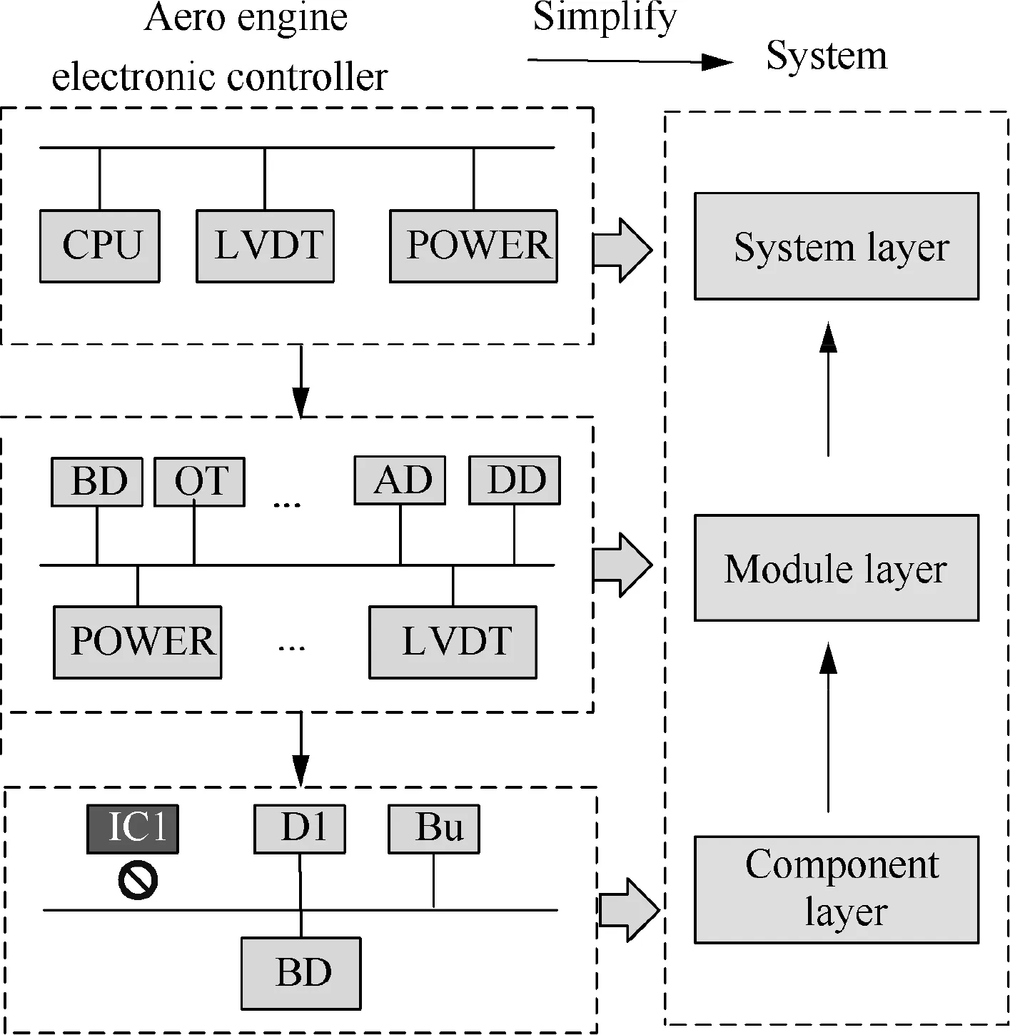
Fig. 1 A three-layer avionics system.
It is assumed that m0and m1are the development rate of FMs in C0and C1. m1changes because of the physical impact of m0. The physical impact lasts for Δt until the physical impact disappears. Subsequently, m1returns to the original development trace, as shown in Fig. 2. The influence of IFC can be divided into three phases, including normal operation phase, physical impact phase and fault coverage phase.
2.1. Normal operation phase (t <t1)
The development of a FM can be described as a random process.The development rate m0can be illustrated by the Wiener process and the degradation processis stochastic process,


Fig. 2 Development rate of m0 and m1.
With the progress of degradation, the damage is accumulated. C1will fail when the accumulation Y(t) exceeds the threshold H. The time t1can be obtained by
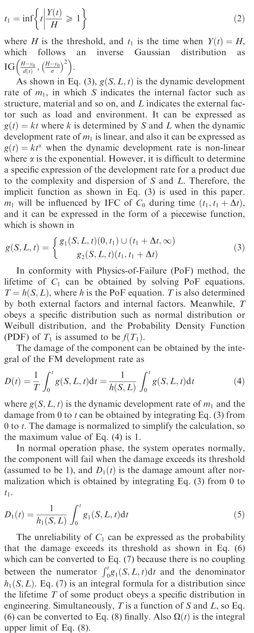

where D1(t)is the damage function of m1in normal operation phase, andis the Cumulative Distribution Function(CDF) of m1in this phase.
2.2. Physical impact phase (t1 ≤t <t2)
Assume Δt is a random variable and obeys normal distribution as

where μ and σ are the mean and standard deviation of the distribution respectively. Δt can be evaluated with Probabilistic Physics of Failure (PPoF) method. This phase can be divided into acceleration phase and recovery phase.

2.2.2. Recovery phase (t1+ Δt ≤t <t2)
After Δt, the physical impact of C0disappears. At time t2, the failure of C1is detected and covered by the system. The damage and the CDF of m1are shown in Eq. (15) and Eq. (16)respectively.

2.3. Fault coverage phase (t >t2)
In this phase, C1fails. Because it is an essential component to the system,the failure of C1results in system failure.Based on the non-repairable assumption, the reliability of the system drops to 0 at that moment.
3. Failure behavior for FM groups

When k FMs are affected in each component, and the reliability is calculated by Eq. (20) whereis the reliability of each FM affected by IFC.
4. Modeling method based on a revised BDD
4.1. Modeling method of BDD

Fig. 3 FMT of acceleration effect.
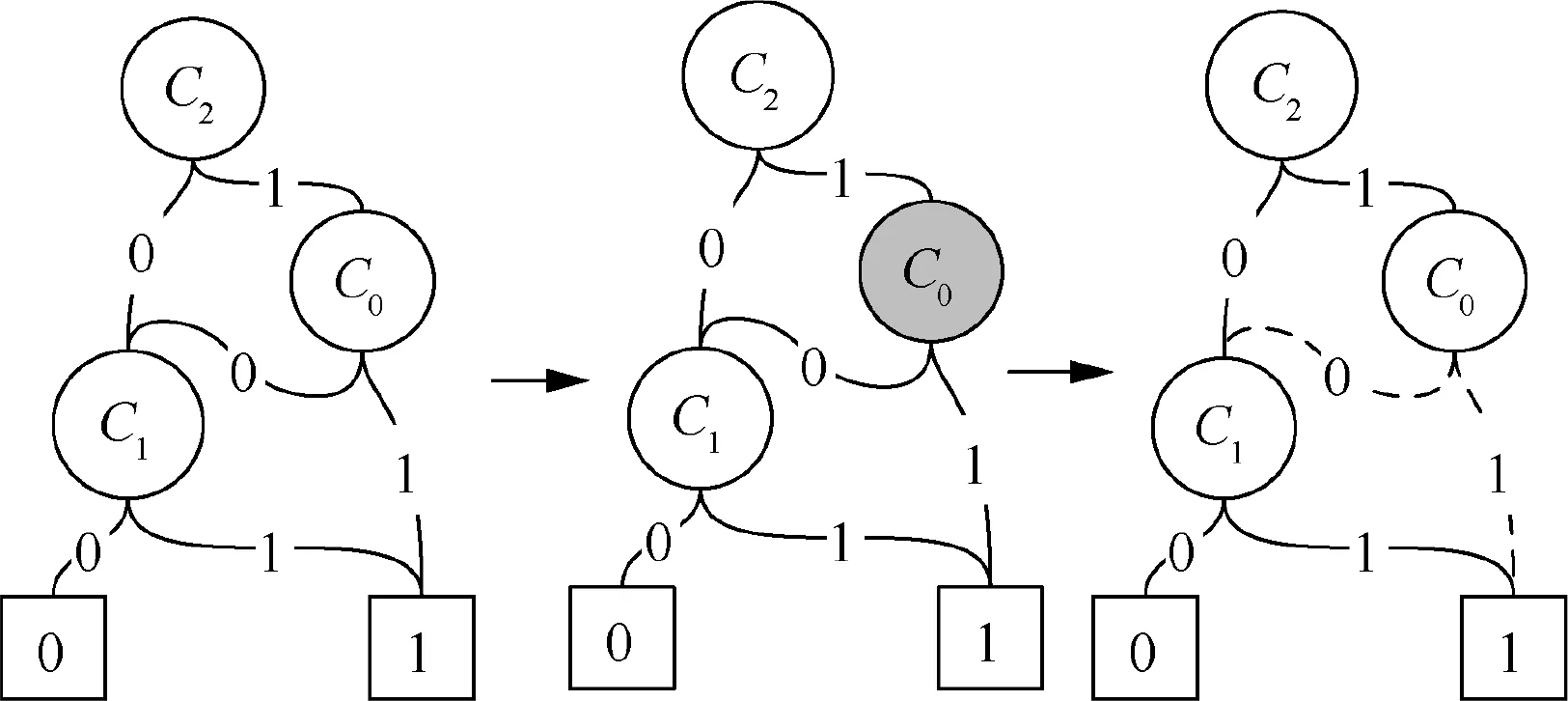
Fig. 4 Improved BDD model.
In order to describe the dependence among FMs, the Fault Mechanism Tree (FMT)40is implemented in the case. As shown in Fig. 3, C0is an external trigger source whose failure will change the environmental loads. MACC indicates the acceleration effect. Not all FMs in C1are accelerated by C0,only FMs that are sensitive to environmental loads will be accelerated, and these FMs are turned intoafter acceleration.
FMT can be solved by BDD and Monte Carlo (MC) simulation method.39The traditional BDD method should be improved for integrating Fault Coverage(FC)and IFC events into the model, and the process is shown in Fig. 4.
In Fig. 4, in physical impact phase, FMs in component C1will be accelerated by the failed componentC0.Therefore,C0is filled with gray, which represents the physical impact. If the physical impact disappears in the fault coverage phase,replace the solid line of ‘0’ and ‘1’ edges in BDD with dotted lines,which means that the system reliability will not be affected by C0, and it will remain in the BDD mode.
4.2. Modeling methods and processes
To solve the system reliability model, a combination of BDD and MC method is proposed.The modeling methods and processes are shown in Fig.5,and the simulation process is shown in Table 1. First, by applying the PPoF method, the Time to Failure (TTF) distribution of each independent FM can be provided. Second, samples of each FM can be obtained based on the distribution. The reliability of each component with each FM is gained at each discrete time point. Third, using the BDD logic, the value of each non-sink node is calculated at each discrete time point. Finally, the failure probability and reliability are calculated at each discrete time point and the reliability dynamic curve is obtained.
5. Case study
The aero engine electronic controller controls the engine by receiving the operating condition signals from various sensors.It consists of CPU module,POWER module,and LVDT module, which are shown in Fig. 6. The detection and prognostic device are designed to monitor the operation parameters and detect the failure.However,because of IFC,some of the component failure may not be detected or located, and the failure behavior will change.
The system can be divided into three layers. The first layer is the component layer, which consists of many types of electronic components.The second layer is module layer including three modules described as the above.The third layer is system layer that represents the electronic controller. Because of the IFC, the failure of IC1 fails to be detected, and it accelerates the development rate of the FMs in other components.Table 2 shows the correlation among FMs and the parameters used in reliability simulation. The distribution of each FM is calculated with PPoF method.
In Table 2, TF represents thermal fatigue, VF is vibration fatigue, EM is electro-migration, TDDB is time dependent dielectric break, HCI is hot carrier injection, SDDV is stressdriven diffusive voids, and ESD is electrical stress discharge.NBTI is negative bias temperature instability. R1_m1 represents the first FM of R1 which is VF. MACO represents competition relationship between FMs, MADA is mechanism damage accumulation, and MACC indicates that IC2 is affected by IC1 and the rate of FM in IC2 is accelerated.
The FMT of IC1 and IC2 is shown in Fig.7.Both IC1 and IC2 contain two competing FMs,VF and TF,the FMT of IC2 contains an external trigger source IC1 in addition which means that the failure of IC1 will make the development rate change from TF to TF’, and furthermore VF and TF’ are still MACO.
The FMs in Buffer Device (BD), Operational Transformer(OT) and D1 are not affected by IC1 because the FMs of Bu and D1 are mainly affected by electrical load and vibration,which are not sensitive to temperature.OT is installed far from IC1, and the reliability is also not affected by the failure of IC1. Therefore, a conclusion can be obtained that whether the development rate of FM is affected by IFC depends on whether the FM is sensitive to IFC or whether the component is installed near the failed component.
To simplify the analysis, the BDD mode of the avionics controller is established, which is shown in Fig. 8.
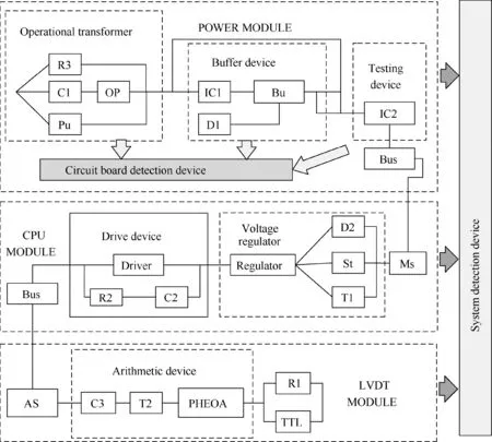
Fig. 6 Structure of aeroengine electronic controller.

?
The main function of buffer circuit in power module is buffering, which will not be affected by the failure of IC1.However, it generates a large amount of heat and affects the surrounding environment, which will change the development rate of the heat-related FMs in the component nearby. Many FMs are sensitive to high temperature. The BDD mode of the FMs correlation is very similar with Fig. 4.
6. Discussion

Fig. 7 FMT module of IC1 and IC2.

Fig. 8 BDD mode of aero engine electronic controller.
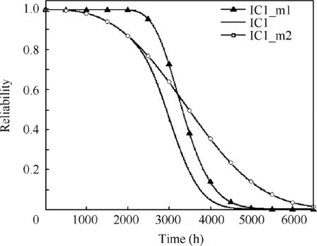
Fig. 9 Reliability of faulty IC1.
As shown in Table 2, the lifetime or reliability of IC1 is determined by the competition of two FMs, TF and VF. The dynamic reliability of component IC1 is shown in Fig. 9. The solid line represents the actual reliability curve of device IC1.Solid lines marked with blank circle and solid triangle in Fig. 9 represent the reliability of IC1 under the independent FMs, TF and VF. From the simulation results, it can be concluded that the device IC1 fails at 5000 h. The failure of IC1 will generate heat and affect the failure rate of peripheral components.Compiling the algorithm in MATLAB,the total time spent in computing the reliability of IC1 on a typical personal computer(Dell Inspiron 14R-7420,i5-3230M CPU 2.60 GHz)was 1.67 s. Monte Carlo simulation algorithm runs very quickly because it does not involve IFC calculation and IC1 has fewer parameters.
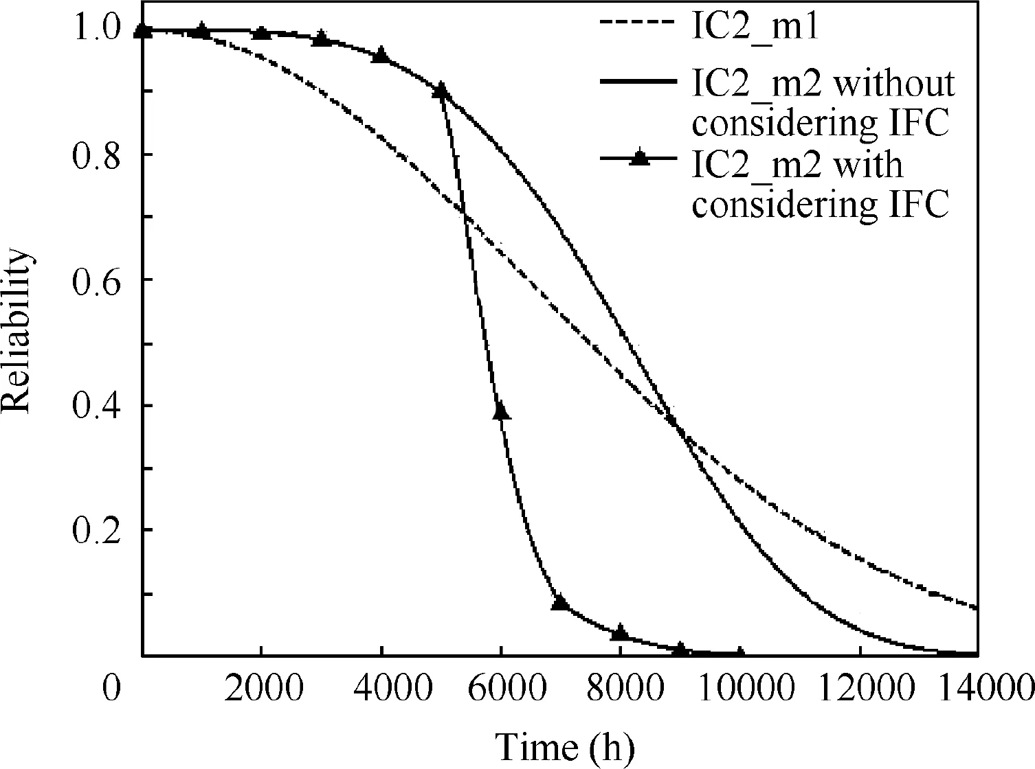
Fig. 10 Reliability of FM IC2_m1 and IC2_m2.

Fig. 11 Reliability of IC.

Fig. 12 Reliability of components in power.
The solid line and the dotted line in Fig. 10 show the reliability of the IC2_m1 and IC2_m2.When IC1 fails and releases a large amount of heat, the development rate of IC2_m2 changes (shown as the solid line marked by triangle) because it is an FM sensitive to temperature elevation. Therefore, the reliability of IC2_m2 decreases significantly after 5000 h.IC2_m1 is VF that is not affected by temperature stress, and its reliability is not affected. The meantime of the physical impact of IC1 is 2000 h,and this is the reason why the reliability curve of IC2_m2 becomes flatter after 7000 h. The failure time of IC2_m2 after considering IFC of IC1 is 10,000 h,while the failure time will be 14,000 h when the failure of IC1 is property covered. Compiling the algorithm in MATLAB, the total time spent in computing the reliability of FMs in IC2 on a typical personal computer (Dell Inspiron 14R-7420, i5-3230M CPU 2.60 GHz) was 6.13 s.

Fig. 13 Reliability of power module.
Fig. 11 illustrates the reliability of IC2, in which the solid line is the reliability of the IC2 without considering IFC and the solid line marked with solid triangle shows the reliability of the IC2 after considering IFC. It can be seen that the reliability of IC2 decreases sharply from 5000 h to 7000 h after considering IFC, because the FM of IC2 is impacted by the physical effect of IC1. From Fig. 5, the failure of any of the three components, IC, BD or OT will result in the failure of the power module, which will be detected and covered. Then the power module requires maintenance or replacement. It can be seen from Fig. 10 that the mean failure time of power modular is 10000 h if the failure of IC1 is uncovered, while the value will be 12000 h if the failure of IC1 is detected and covered.Compiling the algorithm in MATLAB,the total time spent in computing the reliability of IC2 on a typical personal computer(Dell Inspiron 14R-7420, i5-3230M CPU 2.60 GHz)was 6.15 s.When calculating the reliability of IC2,the running time is longer than that of IC1, because Eqs. (4)-(16) are used in MC simulation program.
Fig. 12 is the reliability of component IC2, OT and BD in the power module, where IC2(1) represents the reliability of IC without considering the influence of IFC and IC2(2)represents the reliability after considering the influence of IFC.The dotted line and the solid line marked with blank circle are the reliability of BD and OT. From Table 2, the FMs of Bu and D1 are mainly affected by electrical load and vibration; therefore they are not affected by the failure of IC1.OT is installed far from IC1,and the reliability is also not affected by the failure of IC1. The physical influence is related to the location of the components and their sensitive type of loads and environmental stress.Compiling the algorithm in MATLAB,the total time spent in computing the reliability of IC2, BD, OT on a typical personal computer (Dell Inspiron 14R-7420, i5-3230M CPU 2.60 GHz) was 8.57 s.
Fig.13 is the reliability of the power module,in which the solid line with triangle represents the condition that IFC is considered.The reliability of the power module is determined by BD,IC2 and OT. It can be seen from Fig. 13 that the mean failure time of power modular is 10000 h if the failure of IC1 is uncovered(IFC), while the value will be 14000 h if the failure of IC1 is detected and covered.The IFC may affect system behavior,without considering IFC, the system maintenance intervals may reduce,and thus the maintenance costs will increase.Compiling the algorithm in MATLAB, the total time spent in computing the reliability of IC1 on a typical personal computer (Dell Inspiron 14R-7420,i5-3230M CPU 2.60 GHz)was 9.73 s.
The reliability of power module is much smaller than the LVDT and CPU circuit board because of the load and structure complexity.It can be analyzed from the BDD module that any circuit board failure will lead to system failure and the same conclusion is obtained when solving the reliability of the aero engine electronic controller.
7. Conclusions and future studies
(1) This paper proposes a phased system behavior model and a combinational simulation method to evaluate the impact of IFC in avionic system, which has three detection layers including the component layer, the module layer and the system layer. If it is not covered at the component layer, an FM will propagate through the system. When the propagation develops to some extent, it will result in the failure of the second layer which can be detected and covered. Dynamic reliability of the affected component and the system are analyzed,which includes the normal operation phase,the physical impact phase and the fault coverage phase.
(2) The proposed modeling method combines the BDD with Monte Carlo method. By applying the logic extracted from BDD, the complex behavior of the system considering IFC effect can be simulated. As a case, the failure behavior of an aero engine electronic controller with IFC effect is studied. The results show that in the IFC system, failures in the uncovered layer can affect other layers. When the uncovered failure occurs, the development rate of the affected FM will be promoted, which will change the failure behavior of the system and result in system performance degradation. Without considering IFC, the system maintenance intervals may reduce,and thus the maintenance costs will increase.
Declaration of Competing Interest
The authors declare that they have no known competing financial interests or personal relationships that could have appeared to influence the work reported in this paper.
Acknowledgments
This work was funded by the National Natural Science Foundation of China (Nos. 61503014 and 61573043).
 CHINESE JOURNAL OF AERONAUTICS2020年12期
- CHINESE JOURNAL OF AERONAUTICS的其它文章
- Design and experimental study of a new flapping wing rotor micro aerial vehicle
- CFD/CSD-based flutter prediction method for experimental models in a transonic wind tunnel with porous wall
- Prediction of pilot workload in helicopter landing after one engine failure
- Study of riblet drag reduction for an infinite span wing with different sweep angles
- Modulation of driving signals in flow control over an airfoil with synthetic jet
- Strong interactions of incident shock wave with boundary layer along compression corner
