The Axial Flow Fan Design for an Acoustic Wind Tunnel*
2020-01-18 02:31:20
风机技术 2019年6期
(Facility Design and Instrumentation Institute,China Aerodynamics Research and Development Center,Mianyang Sichuan China.qxl@cardc.cn)
Abstract:An experimental study on the design of an axial-flow fan for the 1.8-by 1.4-m acoustic wind tunnel was carried out.The fan was designed using arbitrary vortex method to improve the aerodynamic performance.The noise generated by the fan was reduced by lower fan rotation speed,more reasonably matched rotor-stator blade number,stator backward-swept angle and rotor-stator spacing.The aerodynamic test results show that the highest wind speed required in the test section is satisfied,and when the fan rotational speed is 650rpm,the fan reaches the highest aerodynamic efficiency(90%)and the whole fan also has the highest aerodynamic efficiency(84%).Moreover,the acoustic test results show that the Overall Sound Pressure Level(OASPL) at the outlet is 114dB when the winds peed in the test section reaches 80m/s.The combination of the arbitrary vortex method with noise control methods is proved to be a good design approach for the axial fan of other acoustic wind tunnel.
Keywords:Fan,Design,Acoustic,Wind Tunnel
0 Introduction
The acoustic wind tunnel which has very low background noise level to measure aerodynamic sounds is important and very useful for developing quiet and agreeable airplanes and vehicles[1].The major noise source in such a wind tunnel is the fan.The fan blade passing frequency and fan blade/stator interaction contribute to the tonal background noise in the test section,and the broadband fan noise is also an important source of broadband background noise[2].To reduce the contribution of fan noise to the background noise in the test section,reduction of the fan noise and attenuation of the propagation of fan noise in the wind tunnel circuit are considered.If a fan with lower noise is available,more acoustic liner and other acoustic treatments will not be needed,and the cost of an acoustic wind tunnel can be lower.Meanwhile,a fan with high aerodynamic performance can reduce the power required for the operation of wind tunnel and improve the flow qualities in the test section.Hence the design technology of low noise fan with high aerodynamic performance is a key technology in the design of aero-acoustic wind tunnel.
This paper presents the design methods and validation tests for the axial fan in an acoustic wind tunnel in China Aerodynamics Research and Development Center(CARDC).This acoustic wind tunnel(Figure 1)has two test sections,one with solid wall and the other with open jet.The dimensions of the test section are 1.8m×1.4m(width×height),and the maximum speeds of the solid wall and open jet test sections are 105 m/s and 70 m/s,respectively.Hence,a fan system with high quality aerodynamic and acoustic performances is required.To achieve such high aerodynamic performance,the arbitrary vortex method is employed to optimize the geometry of fan blades and stators,and various noise reduction methods are used to reduce the fan noise.
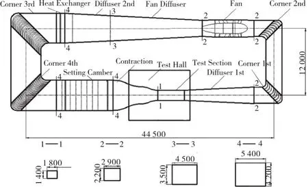
Fig.1 The outline of 1.8×1.4m acoustic wind tunnel
1 Aerodynamic Design
1.1 General Acoustic Considerations
For an acoustic wind tunnel,the fan must be viewed as the strongest single sound source in the total circuit.Unlike in conventional wind tunnels,the fan efficiency does not have the highest priority,but rather the primary emphasis is on the spectral minimization of the radiated sound power[3].So,in the fan design progress,considering the acoustic aspects instead of aerodynamic performance at the very beginning is important to fulfill the objectives in terms of noise emission[4].To make the fan noise lower,the primary design parameters related aerodynamic performance that influence the acoustic emission are listed below:
1)Maximum tip speed:Reducing the fan tip speed is an effective way to reduce fan noise since the sound power generate by a fan blade increases roughly with 5th power of the flow velocity measured in the relative frame of reference[5].
2)Details of blade shape:A well flow condition of fan blade rows can reduce impact on noise through the size and characteristics of the generated vortex.A better load distribution of fan blade is also important to noise reduction since it has the potential to shift slightly the distribution of sources along the airfoil in order to generate acoustic interferences at high frequencies.
3)Axial separation between the rotor and stator:Large axial distance between the fan blades and outlet guide vanes is also widely adopted as an effective method in passive control of fan noise[6-7],although the extended rotor-stator spacing may slightly influence the aerodynamic performance of the fan and increase the overall weight of the fan system.
4)Tip clearance:Noise caused by unsteady behavior of vortical flow near the rotor tip in axial fan is also should be minimized.Tip flow noise can be increased by enlarging the gap between the blade tip and the housing[8].A relative tip clearance of 0.001 D was found to be sufficiently small[9].
1.2 Aerodynamic Design Method
The free vortex design method and the arbitrary vortex method are two widely used methods for fan design,and both require the assumption of two-dimensional flow.The free vortex method is widely used in the design of axial fan which satisfactorily meets the design requirements of low speed wind tunnel,mine ventilation system,cooling system,and the details of this method have been described by Collar[10],Pope[11]and Wallis[12].This method also assumes that the flow velocity has no radial component,and the theoretical axial velocity and the total pressure rise of the fan are both constant along the fan radius.In contrast,the arbitrary vortex method does not require radial equilibrium and a real velocity profile can be applied in the fan design procedure.Moreover,fan design with higher aerodynamic performance can be achieved with this method.For example,Van Ditshuizen[13]used this method to design the pilot fan of NLR LST,whose efficiency reached 92%.For this axial fan,the aerodynamic design aims to achieve higher fan efficiency with the acoustic considerations mention above,so the arbitrary vortex method is selected.The specific fan design requirements are listed in Table 1.
Tab.1 Technical requirement specification for the fan
1.2.1 Fan Blade
With the arbitrary vortex method,the fan system can transform the oncoming skewed velocity distribution into a more uniform distribution at the rotor and stator exit by optimizing the swirl velocity component with radius.Thus,the flow leaving the stator has a sufficiently uniform profile of velocity before entering the post-fan diffuser,and the intermittent type of premature separation is avoided.Moreover,adjusting the load distribution on the blade leads to larger output work at the tip of the blade,so the fan can achieve higher efficiency at lower rotational speed.The swirl coefficientεscan define as a linear distribution along the radius:

Wherexis the dimensionless radius,and bothaandbare constants.
The design point is selected corresponding to the solid wall test section with the maximum wind speed 105m/s.The velocity upstream of the fan blades in the 1.8m×1.4m acoustic wind tunnel is assumed the same as a 0.9m diameter fan of the 0.55m×0.4m acoustic wind tunnel,since the two wind tunnels have the similar airline and the two fans have the same hub-tip ratio.The inlet velocity profile is set as below that was tested before.

WhereU1is the axial velocity at the fan inlet,Uis the mean velocity at the fan cross-section.
Once the swirl velocity and the axial velocity at the fan inlet are known,the axial velocity at the fan rotor outletU2and the axial velocity at the stator outletU3can be obtained from the following two equations.

Whereλsis the advance ratio,xUis the dimensionless radius which the local axial velocity is equal to the mean velocity.
After the axial velocities at the fan rotor outlet and stator outlet have been derived,the chord lengths and setting angles of the rotor and stator blades can be determined according to the detailed design procedure introduced in reference[14].
Figure 2 shows the designed profiles of axial velocity at different fan locations.By adjusting the blade loading,more uniform velocity distributions can be obtained at the rotor outlet and stator outlet.Consequently a significant redistribution of axial energy occurs in the fan plane and the momentum of the flow near the fan tip is significantly improved.
Figure 3 shows that the predicted lift coefficient decreases along the radius in both the solid wall and open jet test sections.The maximum lift coefficient reaches 0.87,which is far below the blade stall lift coefficient of 1.3(since the“Gö 797”airfoil is employed as the profile of rotor blade).Meanwhile,enough margin of fan pressure rise is available in case of increased pressure loss in the wind tunnel.

Fig.2 Axial velocity versus x at different location

Fig.3 Lift coefficients versus x with different operating point
2 Acoustics Design
In the stage of aerodynamic design,acoustic parameters are considered first,the aerodynamic performance of the fan is optimized by improving the fan efficiency with the arbitrary vortex method and preventing flow separation at the fan tip and hub.In the stage of acoustic design,fan noise source control and fan noise level reduction are considered to develop a low noise fan based on the aerodynamic design result.Because the fan is the largest noise source in the wind tunnel circuit,most efforts of noise reduction in the test section are directed at attenuating the noise generated by the fan.Other noise sources in the wind tunnel will only become important once the fan noise has been reduced to very low levels.
The control of fan noise sources is implemented in three steps.First,the numbers of rotor-stator blades are selected to eliminate the rotor-stator tonal noise by cutting-off the first blade passing mode.The most famous design rule regarding fan geometry is the Tyler-Sofrin rotor-stator selection criterion[15],which is useful to get a cut-off blade passing frequency to reduce interaction noise.According to this criterion,the proposed fan should have twenty rotor blades and twenty-seven stator blades.Second,the rotor-stator spacing is optimized to weaken the impinging wakes,and the selected axial distance between the trailing edges of the rotor blades and the leading edges of stator blades is 2 times the chord length of rotor blade.Third,stator sweeping introduces a spatial shift of the noise sources,which induces acoustic interferences,and substantialnoise reduction can be achieved,especially for the interaction tones[16-18].Accordingly,30-degree backward sweeping is employed on the stator blades.Meanwhile,15-degree backward swept tail cone supporting vanes and 15-degree forward swept nose cone supporting vanes are applied.
Acoustical treatment is used to absorb the noise radiated by various fan noise sources.All the flow surfaces within the fan inlet transition,the outlet transition and tail cone sections are acoustically treated,except for that along the nosecone.All the acoustical treatment has 300-mm thick sound absorptive material covered with perforated galvanized steel sheet on the airflow side.In all perforated sheets,holes with nominal diameters of 5 mm are located on staggered centers(45°or 60°)to form the porosity of 35%,and the thickness of the perforated sheets is 1.6 mm.The sound absorptive material is centrifugal glass wool with density of 32 kg/m3.
3 Fan Design Result
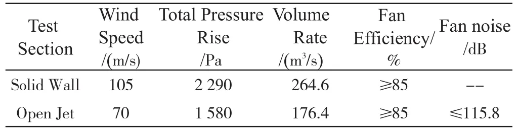
The designed fan(Figure 4,Figure 5,Figure 6)has 3.1-m diameter and 0.6 hub-tip ratio,and at the selected maximum fan speed of 720 rpm,the fan power is 900 kW.The length of the whole fan section is 9.3 m,including a 3-m long fan inlet transition section downstream of corner 2(Figure 1)and a 2.8-m long fan outlet transition section.Ahalf ellipsoid with ellipticity of 2 is employed as the nosecone,and the aft diameter of the tail cone end is 0.65m.NACA0009 and NACA0012 airfoils are employed as the profiles of nose cone supporting vane and tail cone supporting vane,respectively.

Fig.4 Sketch of the designed fan
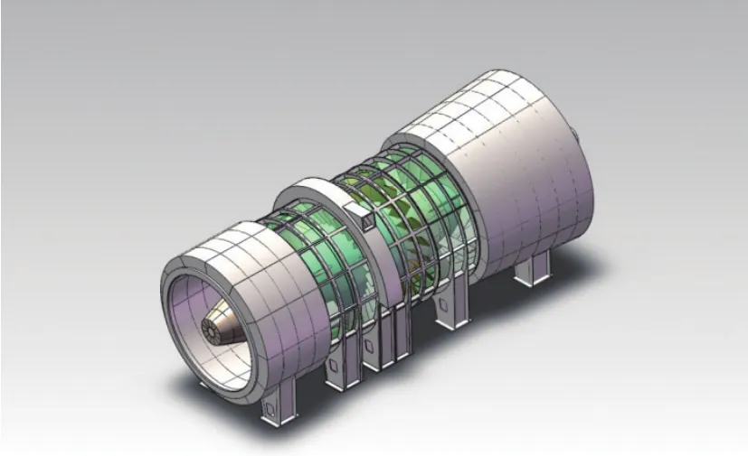
Fig.5 The 3D model of the designed fan
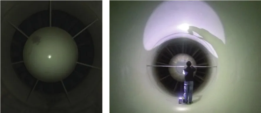
Fig.6 Photos of the fan during testing phase
The fan rotor has twenty blades with“Gö797”profile over the whole blade span,and the stator has twenty-seven blades with NACA 4 415 profile and constant chord length along the span.The distance between the rotor blades and stator blades is 700mm,which is 2 times of the chord length of rotor blade.The blade tip-casing clearance is selected to be less than 3mm,for minimizing the aerodynamic loss at the blade tip and reduce noise.The geometrical characteristics of the rotor and stator blades are summarized in Table 2.
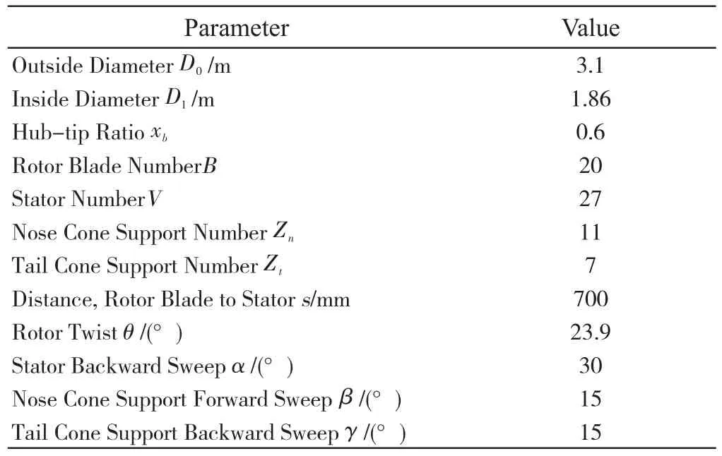
Tab.2 The fan configuration
4 Fan Test Description
The aerodynamic and acoustic performances of the designed fan are tested during the wind tunnel commissioning test.The whole-fan efficiency and fan efficiency are two important indexes for evaluating the fan aerodynamic performance.Different equations are used to calculate the two indexes more exactly:
The whole-fan efficiencyηFis defined by Eq.(5)
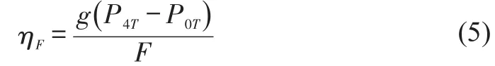
Wheregis the flow volume rate,P0Tis the total pressure upstream of the fan inlet transition,P4Tis the total pressure downstream of the fan outlet transition,Fis the fan shaft power.
The fan efficiencyηfis defined by Eq.(6),which follows as
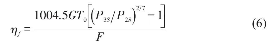
WhereGis the mass flow rate,T0is the total temperature at the inlet of the rotor blade,P2Sis the static pressure upstream of the fan rotor blade,andP3Sis the static pressure downstream of the stator.
One total pressure rake is installed at the upstream of the fan inlet transition,consists of nine steel tubes with 2-mm internal diameters and located at 500-mm intervals.One single total pressure tube is mounted on a traverse downstream of the outlet transition to get the distribution of P4T.Two sets of 4 static surface taps are installed upstream of the fan rotor and downstream of the stator to measure the pressure rise through the fan stage.A pressure scanner is applied for total pressure measurement,with scanning range of-10.3 kPa~10.3 kPa and accuracy rating of 0.3%.
The acoustic measurements are conducted with oneB&Kmicrophone covered by a mesh,which filters out turbulence pressure fluctuations but allows for the transmission of acoustic waves.The microphone is located at about 3.3 meters downstream of the stator.The measuring range of each microphone is 0-160 dB,with accuracy of 0.1dB.The data recording time is 10s,and the sampling frequency is 51.2 kHz.
5 Results and Discussion
5.1 Aerodynamic Performance
To obtain the fan efficiency under typical wind tunnel operational conditions,the total pressure rise is measured at different flow velocities in each type of test section.For the solid wall test section,the fan rotational speed(N)is varied from 270 rpm to 720 rpm,and the wind speed in the test section ranges from 39.9 m/s to 108.4 m/s.For the open jet test section,the fan rotational speed(N)is varied from 200 rpm to 650 rpm,and the wind speed in the test section ranges from 21m/s to 70 m/s.
Figure 7 shows the whole-fan efficiency with different wind speeds for both solid wall and open jet test sections.As the flow velocity increases,the whole-fan efficiency increases in each type of test section.The peak whole-fan efficiency reaches 84%at the flow velocity of 70 m/s in the open jet test section,and the peak efficiency reaches 82%at the flow velocity of 108.4 m/s in the solid wall test section.

Fig.7 The whole-fan efficiency as a function of flow velocity in test section
The fan efficiencies for different types of test section are plotted in Figure 8.As expected,the fan efficiency increases with the increase of flow velocity in the test section.For the open jet test section,the fan efficiency lays in the range 84%≤ηf≤90%,and the maximum fan efficiency is reached at the wind speed of 70 m/s.For the solid wall test section,thefanefficiencylaysintherange82.8%≤ηf≤88.5%and at 108.4 m/s wind speed in the test section,the fan efficiency is 88.5%when the rotation speed is 720 rpm.For both solid wall and open jet test section with maximum wind speed,the fan efficiency is superior to the design requirement of 85%.
5.2 Acoustic Performance
The acoustic performance of the designed fan is tested with the solid wall test section,since the wedges in the anechoic hall and the collector of the open jet test section in the 1.8m×1.4m acoustic wind tunnel have not been assembled.The fan acoustic performance is measured in two wind speeds,60m/s and 80m/s,and the fan rotational speeds are 410rpm and 540 rpm,respectively.The acoustic signals are analyzed after Fast-Fourier-Transform(FFT)in the range of 4 Hz to 25.6 kHz with the B&K PULSE LabShop software.
Figure 9 shows the test results of sound pressure level at the fan outlet with two different wind speeds.The broadband noises at both locations have similar profiles,but the tonal noise has different peak fervency.At the wind speed of 60m/s and 80m/s,the peak fan SPL is located at 315Hz and 400Hz,which corresponds to the second blade passing mode,respectively.The OASPL at the fan outlet is 109.9 dB with the wind speed 60m/s,and the OASPL at the fan outlet is 114.2 dB with the wind speed 80m/s.From the fan acoustic test results,the noise suppression methods are proved to reduce the fan interaction noise and broad band noise.

Fig.8 The fan efficiency as a function of flow velocity in test section
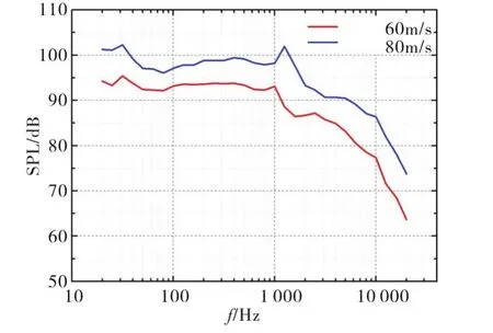
Fig.9 The 1/3 octave spectra of the fan outlet for solid wall test section with different wind speeds
6 Conclusions
An axial fan system is designed for the 1.8-by 1.4-m low speed aero-acoustic wind tunnel with closed circuit in CARDC,and the validation test results show that the fan has satisfying the design requirements well.
In the design stages,the arbitrary vortex method is employed to optimize the configurations of rotor blades,stator blades,and various noise reduction methods are used to reduce the fan noise.It is believed that this methodology can also be applied for the design of axial fan in other acoustic wind tunnels.
The following lessons are learned in the design process:
1)For an axial fan used in acoustic wind tunnel,some fan aerodynamic design parameters are needed to be selected at the beginning of the design process for fan noise reducing purpose.
2)The arbitrary vortex method works to produce more uniform distribution of flow velocity in the fan outlet and improve the fan efficiency.The fan efficiency at the design point is 90%,which surpasses the design requirement of 85%.
3)The methods employed for fan noise reduction effectively control the fan noise level.The first mode of blade passing frequency of the fan is successfully cut off,and the fan broadband noises are control well.