生物质羟基磷灰石作为模板制备三维石墨烯
2019-10-14 07:56王可心史刘嵘王铭展杨皓刘忠范彭海琳
物理化学学报 2019年10期
王可心,史刘嵘,王铭展,杨皓,刘忠范,3,*,彭海琳,3,*
1北京大学化学与分子工程学院,分子动态与稳态结构国家重点实验室,北京分子科学国家实验室,纳米化学研究中心,北京 1008712北京大学前沿交叉学科研究院,北京 1008713北京石墨烯研究院,北京 100095
1 Introduction
Graphene, a two-dimensional (2D) hexagonal mesh of monolayer carbon atoms, serves as a versatile building block for graphitic materials of all other dimensionalities. Graphene holds promise in a broad range of fields such as rechargeable batteries,supercapacitors, electrocatalysts and water treatments, thanks to its excellent chemical stability, good electric conductivity and high specific surface area1-5. However, the 2D flakes of graphene readily suffer from π-π stacking between neighboring layers,which may significantly reduce the surface area and severely degrade the excellent electrical properties of graphene6. To prevent the stacking problem, specific 3D graphene (3DG) with porous microstructures should be rationally constructed6. To this end, several bottom-up methods have been developed to fabricate 3DGs thus far. For example, the self-assembly of 2D graphene sheets in solution via van der Waals interactions and hydrogen bonds was commonly utilized to produce 3DGs with random microstructures7. An alternative promising pathway is to directly synthesize 3DGs via the well-established chemical vapor deposition (CVD) method, wherein 3DGs can integrally inherit rich micro- or macro-porous structures from the templates and exhibit well-defined microstructures6,8,9-13.
For templated CVD growth of 3DGs, the physical and chemical properties and microscopic 3D structures of template materials are of crucial importance to the quality and morphology of graphene, as well as the cost of the production process6,11,13-17. Generally, the templates have to be etched to obtain pure graphene materials after growth. However, the pickling solutions after etching are usually wasted in previous works, which is obviously against the principle of atom economy. Herein, we employed bone ashes, a cheap and abundant bio-waste material, as novel templates for the CVD growth of high-quality with bicontinuous microstructures. The bone ash, whose dominant component is hydroxyapatite[Ca5(PO4)3(OH)]18,19, can be etched in diluted hydrochloric acid after the CVD process and forms calcium chloride and phosphoric acid solution, which is exactly a key process in the chemical beneficiations of phosphate rock. So the resultant pickling solution could be used as raw materials for the wet production of phosphoric acid. Furthermore, the bicontinuous microstructures of as-obtained 3DGs, i.e. both the graphene framework and void space are continuous, render it an excellent conducting framework for both electrons and ions in electrochemical devices. Upon the uniform composition of S cathode onto the bicontinuous 3DG, the performance of Li-S batteries are considerably superior to that using reduced graphene oxide as conducting framework.
2 Experimental
2.1 CVD growth of bicontinuous 3D graphene
Commercial bovine bone ashes (kindly afforded by Qingdao Yuzhou Chemical Co., Ltd.) was smashed and grinded in agate mortar to obtain bone ashes powder. Then the bone ashes powder was put on a quartz plate covered by carbon cloth and placed inside a tube furnace. The tube was purged with Ar to remove air and then heated to 1020 °C at a rate of 25 °C·min-1, followed by a constant temperature process of 0.5-4 h under a constant mixed gas flow of Ar (300 cm3·min-1), CH4(10 cm3·min-1) and H2(30 cm3·min-1) for graphene growth. After the furnace was cooled to room temperature, bone ashes@graphene samples were obtained. The powder was immersed in hydrochloric acid :ethanol : H2O (with volume ratio of 1 : 1 : 1) solution to remove bone ashes templates, followed by water washing process for several times to remove extra impurity ions. Finally, the powder in water were frozen in liquid nitrogen and freeze-dried under vacuum, the graphene powder was obtained. Tricalcium phosphate [Ca3(PO4)2], magnesium phosphate [Mg3(PO4)2] and aluminum phosphate [AlPO4] were also used as CVD templates,and the growth condition is the same as above (the growth time is 2 h).
2.2 Synthesis of rGO
Graphite oxide was purchased from Shanghai Ashine Technology Development Co., Ltd. The graphite oxide was ultrasonic dispersed into water followed by freeze-drying to get graphene oxide. Reduced graphene oxide (rGO) was achieved by a low-temperature expansion under vacuum20. The graphene oxide was put into vacuum oven, heated to 200 °C and kept for 4 h to obtain fluffy rGO. The pump was kept operating during the process to maintain high vacuum.
2.3 Fabrication of graphene/sulfur composites
The graphene/sulfur composite cathodes were fabricated through a common melt-diffusion strategy. Graphene materials(3DG or rGO) were mixed with sulfur powder with a mass ratio of 15 : 85 by milling separately. Subsequently, the mixtures were placed in a vacuum oven at 155 °C for 8 h to form graphene/sulfur composites. During this process, sulfur was partly sublimated and the mass ratio of graphene and sulfur became 3 : 7 approximately. This result is further confirmed precisely by Thermogravimetric (TGA) test (Fig. S1, Supporting Information), showing that the mass ratio of sulfur in 3DG/S and rGO/S are 68% and 73% separately.
2.4 Material characterizations
Samples were characterized by SEM with EDS (Hitachi S-4800; acceleration voltage 1-10 kV), TEM (FEI Tecnai F20;acceleration voltage 200 kV), Raman spectroscopy (Jobin Yvon LabRAM HR 800UV; 514.5 nm, 25 mW), XPS (Kratos Analytical Axis-Ultra spectrometer; Al KαX-ray source), TGA(TA Instruments, Q600 SDT; N2flow) and Brunauer-Emmett-Teller (BET) surface area (Micrometer, ASAP2020; N2 flow).
2.5 Electrochemical test
The 3DG/S (or rGO/S) was mixed with conductive carbon black (Super P) and PVDF binder in a weight ratio of 70 : 15 :15, followed by dispersion in N-methyl-2-pyrrolidinone (NMP)to form a slurry. The specific capacity is calculated based on real sulfur mass. Based on the sulfur content in the graphene/sulfur composites, the weight percentage of sulfur in the electrodes(current collector is excluded) are 48% and 51% for 3DG/S and rGO/S separately. After overnight stirring, the slurry was then coated onto aluminum foil and dried at 50 °C in vacuum oven.The areal mass loading of sulfur is about 1.3 mg·cm-2. The electrodes were punched into a disk with a diameter of 10 mm.Then 2025 coil-type cells were constructed in an Ar-filled glovebox with lithium metal as anode. The electrolyte is 1.0 mol·L-1lithium bis(trifluoromethanesulfonyl)imide (LiTFSI) in 1,3-dioxolane/1,2-dimethoxyethane (DOL : DME volume ratio= 1 : 1) with 1% LiNO3 addition. Galvanostatic charge-discharge test was performed on a LAND instrument. The EIS analysis was performed on a Bio-logic VMP3 potentiostat with amplitude of 5 mV in the frequency range of 200 kHz to 10 mHz.
3 Results and discussion
3.1 Preparation of 3DGs
Fig. 1a schematically illustrates the synthesis procedure of 3DGs using bone ashes as the CVD template. Briefly, the bone ashes were firstly grounded and meshed into sub-micrometer particles with sharp edges. Then the bone ashes powders were loaded into the home-made CVD apparatus and heated to 1020 °C for subsequent synthesis of graphene (see Experimental section for details). During this CVD process, few-layer graphene films were grown conformally on bone ashes. We observed that the bone ashes powders were partly sintered during the CVD process. Thereby, the bone ashes powders become less sharp and form a continuous porous structure with graphene coating. Consequently, after removing the bone ashes template in hydrochloric acid, the template-grown 3DG has a unique bicontinuous structure, viz. both the graphene layers and void space are continuous.
To investigate the detailed microstructures of templates and 3DG products, we performed scanning electron microscopy(SEM), transmission electron microscopy (TEM) and spectroscopy analyses. Fig. 1b shows a typical SEM image of the pristine template material produced by the calcination of white bio-waste bovine bones in ambient condition. The template material is highly crystalline hydroxyapatite white powder (inset of Fig. 1b), as confirmed by TEM images (Fig. 1e)and XRD spectrum (Fig. S2a and S2b, Supporting information).After the CVD process, few-layer graphene film was grown conformally on bone ashes templates (Fig. 1c, f). The color of the graphene-coated bone ashes powder template became dark gray (inset of Fig. 1c), while the crystalline phase of hydroxyapatite template kept unchanged according to the XRD measurement (Fig. S2c, Supporting information). To obtain the 3DGs, bone ashes templates were removed by hydrochloric acid solution through the chemical beneficiation process of phosphate rock:
Ca5(PO4)3OH + 10HCl → 3CaCl2+ 2H3PO4
This beneficiation process is moderately fast and complete.Notably, the pickling solution (calcium chloride and phosphoric acid solution) is exactly the intermediate products of wet process phosphoric acid production, whereby industrial grade phosphoric acid can be obtained by further extraction,purification and concentration. Meanwhile, calcium chloride solution can also be utilized in a broad range, such as the production of gypsum (calcium sulfate) or lime (calcium oxide).Therefore, our fabrication method of 3DGs can be effectively integrated with the phosphorus chemical industry, which effectively increase the atom utilization and lower the total costs.
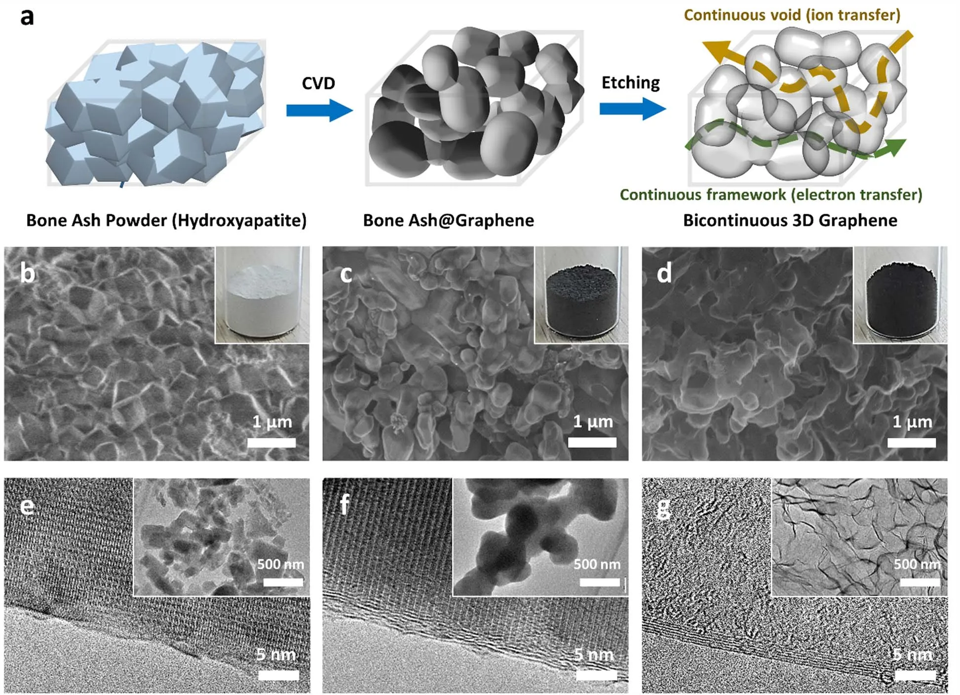
Fig. 1 CVD synthesis of 3DG.(a) Schematic synthesis process of bicontinuous 3D graphene (3DG). (b, c, d) SEM images and corresponding TEM images of pristine bone ashes powder (b),graphene-coated bone ashes powder (c) after CVD growth at 1020 °C for 2 hours, and bicontinuous 3DG after template removal (d). Insets of (b-d) are corresponding optical photographs. (e, f, g) HRTEM images of bone ashes powder (e), graphene-coated bone ashes powder (f), and bicontinuous 3DG after template removal (g).Insets of (e-f) are corresponding low-magnification TEM images.
As a consequence, black powder of as-synthesized 3DGs remained without any detectable residue (Fig. 1d, g). According to TEM and SEM images (Fig. 1d), 3DG is a macroporous material made up of a smooth capsule-like structure with a size of hundreds of nanometers, with few micropores or mesoporous structures. Besides, the graphene layer numbers in 3DG are typically 5 to 10 (Fig. 1g), which means the specific surface area of 3DG will be several times smaller than that of theoretical value of monolayer graphene (2630 m2·g-1). Consistent with the topography and structural characteristics, the 3DG has a specific surface area of 123 m2·g-1. The purity of 3DG were also investigated. Full scan XPS spectrum shows that the 3DGs comprises of C with negligible O constituent (Fig. S3a,Supporting information). The C/O ratio of 3DG is 64, revealing the high purity of 3DGs. Moreover, the signal of C 1s shows a preponderant sp2C ratio, indicating that 3DG is highly graphitized (Fig. S3b, Spporting information).
3.2 Regulating the quality and morphology of 3DG by changing the preparation conditions
We further optimized the graphitization degrees, layer number and porous morphology of 3DGs. We found that the growth time plays a key role in the synthesis of high-quality 3DGs. The graphitization degree of graphene layers can be drastically revealed by elongated the growth time, as indicated by the decreased relative intensity of D band in Raman spectra (Fig.2a). This tendency can be further clearly presented in the Raman D/G band intensity ratio (Fig. 2b). Additionally, the statistical standard deviations of Raman D/G and 2D/G intensity ratio decrease with the increase of growth time, suggesting an enhanced uniformity of 3DGs. High-resolution TEM (HRTEM)characterization shows that the graphene layer number increased statistically with elongated the growth time (Fig. 2c, d). The average layer numbers are 2.7, 4.3, 7.7 and 8.9 for samples with the growth time of 0.5, 1, 2 and 4 h, respectively. Furthermore,the 3D porous morphology evolution is investigated. The sample with the growth time of ~0.5 h showed a flat morphology without a specific 3D structure, while the bicontinuous 3D porous structure gradually emerged by increasing the growth time (Fig.S4, Supporting information). We believe that the microstructure evolution is highly relevant to the layer thickness and uniformity of graphene layers. A short growth time would lead to non-uniform and thin layer graphene, which is not able to support a complex 3D porous structure. In contrast, uniform graphene layer with proper thicknesses are capable of forming a robust 3D architecture.
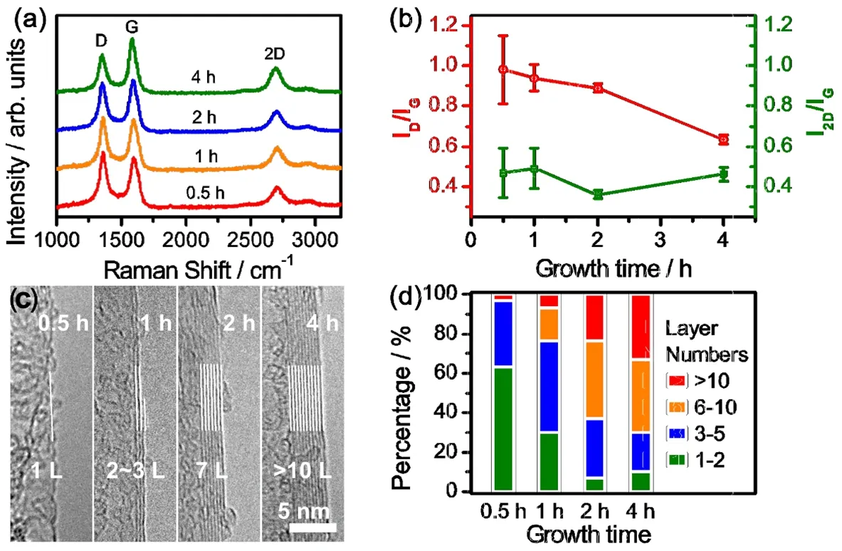
Fig. 2 The evolution of quality and layer numbers of 3DG at different growth times.(a) Raman spectra of 3D graphene with different growth time. (b) The Raman intensity ratios and corresponding standard errors of 2D/G and D/G bands of 3D graphene vs CVD growth time. (c) Typical HRTEM images of 3D graphene with different growth time. (d) Layer numbers distributions of graphene with different growth time.
In addition, the facile CVD method can be extended to a series of metal phosphates templates. Herein, tricalcium phosphate[Ca3(PO4)2], trimagnesium phosphate [Mg3(PO4)2] and aluminum phosphate [AlPO4] were used as templates for CVD synthesis of graphene. Raman analyses show that the quality of graphene synthesized on several phosphate templates are similar with that on bone ashes (Fig. S5, Supporting information).Nevertheless, in light of the low price, the bio-waste bone ashes seem to be fairly promising to the green and scalable production of graphene.
3.3 3DGs as conducting frameworks for sulfur cathodes
Given the high quality and unique bicontinuous microstructures of 3DGs, it is supposed to be a promising candidate for energy storage applications. For instance, Li-S battery with theoretical energy density up to 2567 Wh·kg-1, is a strong candidate for next-generation energy storage devices21-24. However, its practical application is constrained by the intrinsic electric insulation of sulfur and lithium sulfides, which leads to low specific capacity and poor rate performance21,22. In order to overcome this defect, one solution is to combine sulfur with carbon materials such as graphene to improve the overall conductivity of cathode. Hence, as a proof-of-concept demonstration, 3DGs/sulfur composite cathode was fabricated for Li-S batteries. The mixture of 3DGs and sulfur was heated to 155 °C so that molten sulfur was filled into the pores of 3DGs.After the composition with sulfur, the non-flat structure of 3DGs remain unchanged (Fig. 3a, b and Fig. S6a, Supporting Information) and sulfur was uniformly distributed onto the 3DG scaffolds (Fig. 3c, d). As a comparison, reduced graphene oxide(rGO) was also composited with sulfur through same procedure.The rGO/S composite electrode were distinctly caked (Fig. 3e, f and S6b) and S element was uniformly distributed with random congregations (Fig. 3g, h). In comparison with seriously stacked 2D graphene sheets in rGO/S, the non-flat structure of 3DGs kept unchanged even after the harsh melt-diffusion process.Meanwhile, the bicontinuous porous structures of 3DGs offered free space for the uniform dispersion of sulfur.
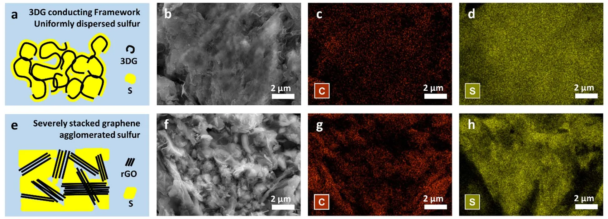
Fig. 3 Characterizations of different graphene/sulfur composite materials.(a) Schematic structure of 3D graphene/sulfur (3DG/S). (b) SEM image of 3DG/S. (c, d) Corresponding 2D maps of energy dispersive spectroscopy (EDS) of C (c) and S (d). (e) Schematic structure of reduced graphene oxide/sulfur (rGO/S). (f) SEM image of 3rGO/S. (g, h) Corresponding 2D maps of EDS of C (c) and S (d).
To evaluate the electrochemical performance of 3DG/S and rGO/S, 2025-type coin cells were fabricated. Electrochemical impedance spectroscopy (EIS) measurements were carried out before galvanostatic test (Fig. 4a). The semicircular loop of 3DG/S in the high-medium frequency region are smaller than that of rGO/S, indicating that 3DG/S have faster charge transfer kinetics, which arises from the superior electric conductivity of 3DGs and electrode architecture of 3DG/S. Notably, 3DG/S exhibited observably improved rate capability in comparison with rGO/S (Fig. 4b). A considerable capacity of about 550 mAh·g-1is achieved even at a high rate of 2C (1C = 1675 mA·g-1) for 3DG/S. Fig. 4c shows the charge-discharge voltage profiles of 3DG/S. The 0.05C curves show a typical profile of sulfur cathode, i.e. two discharge voltage plateaus of ~2.3 and~2.1 V, and one charge plateau of ~2.3 V. The polarization increased with a higher C rate, nevertheless the two discharge plateaus are still well-defined even at a high rate of 2C. As a comparison, the polarization of rGO/S is much higher than that of 3DG/S (Fig. 4d). The superior rate capability and relative low polarization of 3DG may be attributed to its excellent conducting framework for electron transport and abundant void spaces for ion diffusion. The cycling stability was also tested. 3DG/S cathode showed good cycling stability at 0.5C (Fig. 4e). The initial discharge capacity at 0.5C is 830 mAh·g-1and the average cyclic fading is 0.19% in the subsequent the 200 cycles with columbic efficiencies over 95%. By contrast, rGO/S cathode showed low initial capacity of 370 mAh·g-1and complete failure in 50 cycles. All the measurements indicate that the bicontinuous graphene porous acts as an effective conducting framework in the 3DG/S cathode for the efficient transport of electrons and ions, which benefits the long term cycling stability of Li-S batteries.
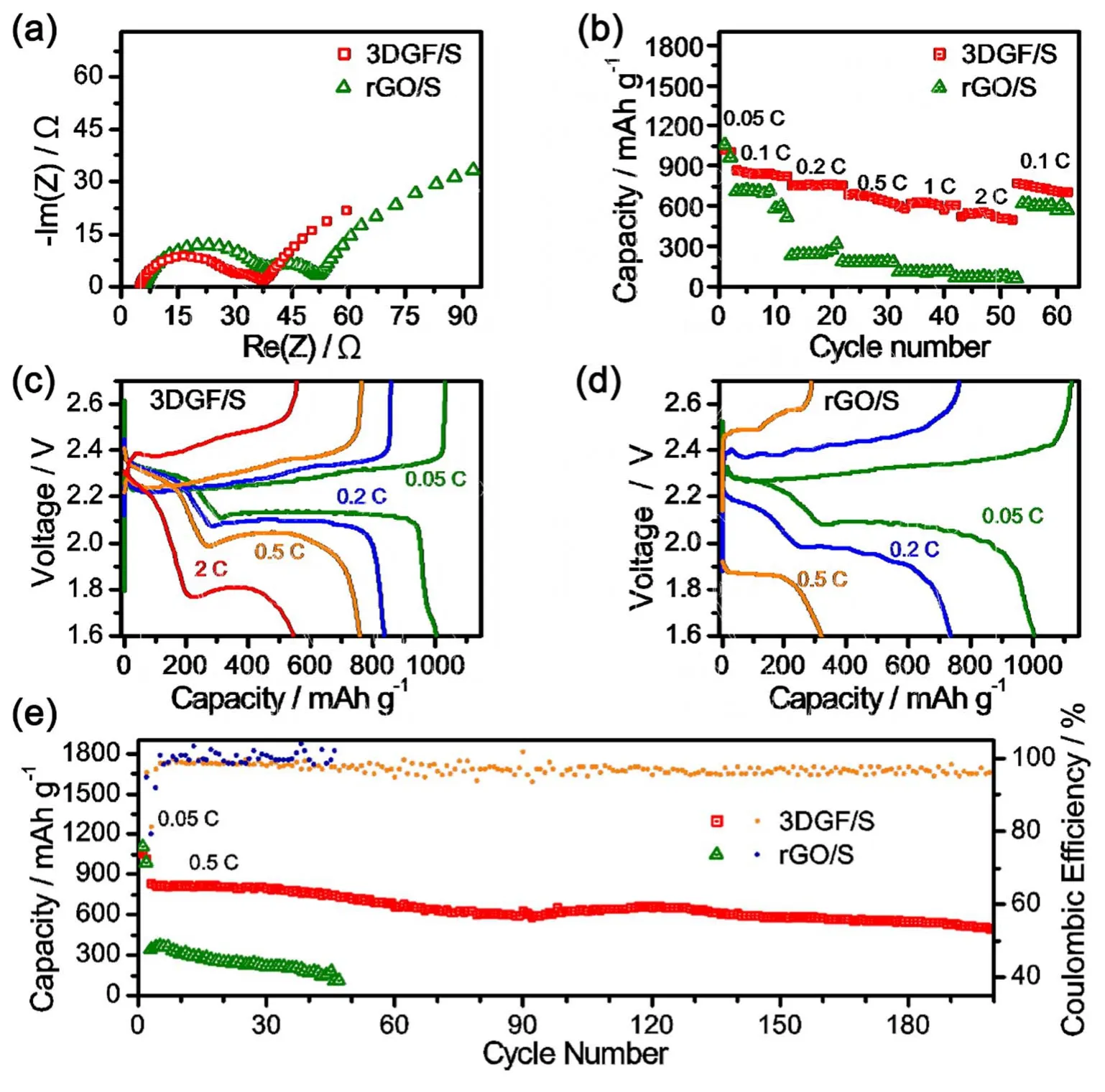
Fig. 4 Electrochemical performances of different graphene/sulfur composite materials.(a) Electrochemical impedance spectra (EIS) at open-circuit voltage of 3DG/S and rGO/S cathodes. (b, c, d) Specific capacity (b) and charge-discharge voltage profiles of 3DG/S (c) and rGO/S (d) cathodes cycled from 0.05C to 2C (1C = 1675 mA·g-1). (e) Specific capacity and columbic efficiency of 3DG/S and rGO/S upon 400 charge-discharge cycles at 0.5C.
4 Conclusions
In summary, 3D graphene with bicontinuous microstructures was synthesized on bio-waste bovine bone ashes via a facile CVD method. The quality of template-synthesized graphene is comparable with these synthesized on the chemically pure counterparts, including tricalcium phosphate, trimagnesium phosphate and aluminum phosphate. The bicontinuous 3D graphene was proven as an effective conducting framework for the efficient transport of electrons and ions in sulfur cathodes of high-performing Li-S batteries. Moreover, the etching process of bone ashes templates is fairly compatible with chemical beneficiation of phosphate rock, thereby enabling the green and complete utilization of this bio-waste materials. Our work opens an avenue to efficient integration of the emerging graphene fabrication and the well-developed phosphorus chemical industry.
Supporting Information:available free of charge via the internet at http://.
猜你喜欢
肉类研究(2022年5期)2022-06-16
昆钢科技(2022年1期)2022-04-19
经济与管理(2022年2期)2022-03-24
湖北科技学院学报(2021年4期)2021-09-24
食品安全导刊(2021年20期)2021-08-30
纺织科学研究(2021年7期)2021-08-14
戏曲研究(2021年3期)2021-06-05
动漫界·幼教365(中班)(2021年1期)2021-04-06
经济与管理(2021年2期)2021-03-15
军事文摘(2020年20期)2020-11-16