Characterizations of friction welding joint interface for AISI 316
Ammar Jabbar Hassan, Taoufik Boukharouba and Djamel Miroud
Mechanical Engineering Departement, Houari Boumediene Universtity of Sciences and Technology, Algiers 16111, Algeria
Abstract Because of heat amount is different from peripheral to central of friction welding interface, which is leaded to vary the characterizations along that interface. Current study, respectively, focused on the effect of different friction pressure on micro-structural and mechanical properties of that friction welding joint interface. Presently, these friction pressures are 110, 130, 150 and 170 MPa while kept all other conditions constant. The effects of different friction pressure on welding interface characterization were investigated by EDX, SEM, tensile, compression, impact and hardness tests. The tensile tests carried out on the standardized test piece with diameter 6 mm and 8 mm, thus, compression tests were extracted from the positions of 0°, 45°& 90° with test specimen of 4 mm diameter and 6.5 mm length at weld center. Whereas, the impact test pieces were picked up in two positions, the first one is symmetrical, which it obtained to the respect of the rotation axis and the interface, on the other hand, the second one is non-symmetrical with the axis of rotation and symmetrical to the interface, for making the notch head coincide with the center of the welded joint, The obtained results showed that with reducing of friction pressure will present lack of bonding increasing from peripheral toward the welding center, which will responsible on reducing of the mechanical properties such as tensile, compression and impact strength.
Key words friction pressure, tensile strength, compression strength, hardness, impact strength
0 Introduction
Friction welding is a solid state welding process which provides welding below melting temperature of the base metal being joined. The first inventing of this technique was recording for the American J.H. Bevington at 1891 by joining metallic pipes, and this method did not take an interesting until 1941 by H.K. Lopstock and A.R. Neelands were inventing friction welding by deposit metal. Soon thereafter, Russians at 1956 gave this process requested impotence, where A.I. Chudikov reported this operation and introduced it as a commercial process[1].
The friction welding process also subdivided mainly into many processes: continuous drive[2-3], inertia[4-5], orbital[6-7], linear[8], friction stir[9-10]and friction stir spot welding[11]. The continuous drive friction welding is a technique that produces coalescence using the heat developed between two surfaces by a combination of mechanically-induced rotational rubbing motion and applied load, one of the part is held stationary while the other rotate and the two are being brought into contact of each other, this technique is a favorite but a distinct method, significantly fast with a short weld time, thus to other characteristics of high reproducibility, sub-melting temperature, low input energy and without inter-metallic formation[12-14].
Typically, friction pressure aids grain growth and microstructure details at the center and peripheryare different. Hence, the central region consists of fine grains while peripheral region consists of coarse grains[15].Friction pressure should be always kept high to achieve better strength because of low friction pressure results lack of bond joint where voids are commonly found[13].
The temperature in the welding center is low relative to that in the peripheral[16], therefore current study try to focus on the microstructure and mechanical properties of that friction welding joint center. High friction pressure is responsible on super heating whereas low friction pressure on uncompleted welded joint. The value of friction pressure is also controlling the amount of heat and metal of flash formation.
The commercial austenitic stainless steel AISI 316 used in the current study is easily weldable. Minimizes harmful carbide precipitation due to welding therefore it is available in wide range of applications such as chemical equipment, medical, pharmaceutical, alimentation, exhaust manifolds, furnace parts, heat exchangers, jet engine parts, photographic equipment, valve and pump trim, digesters, tanks, evaporators, pulp, paper and textile processing equipment, parts exposed to marine atmospheres, tubes and nuclear industries.
1 Experimental procedure
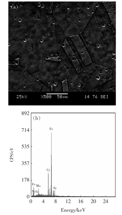
The steel used in the present study was commercial austenitic stainless steel shafts AISI 316 (12 mm diameter and 45 mm length), Table 1 illustrates the amount of alloying elements. While Fig.1 is clearly seemed austenitic equiaxed grains by SEM and EDX observation for parent metal.
Table1Parentmetalalloyingelements(spectrum,wt.%)

CMnSiPSMoCrNi0.0401.5000.6700.0300.0212.9317.939.95

Fig.1ParentmetalSEMandEDXobservation(a)SEM(b)EDX
Friction welding machine used in this work was designed and fabricated as continues drive friction welding machine; it was capable, precise and excellent for automatic controlling of weld conditions. Friction and forging pressure are measured mechanically and electronically. 3 Phase AC motor with brake and 3.5 kW power, operating speed can be varied from 0 to 3 000 r/min and 300 MPa maximum pressure applied. The amount of energy required to achieve welding operation is illustrating as follows[17]:
T=2/3πμpr3
(1)
P= 2/3μFrω
(2)
whereμis the coefficient of friction,pis the pressure applied on the test piece (MPa),ris the radius of the test piece (mm),Fis the load applied on the test piece (N),Tis the torque applied on the test piece (N·mm),ωis the angular speed (rad/s),Pis power. Effect of friction pressure during friction phase is experimental analyzed by present study on the evolution of mechanical and metallurgical properties.
Selecting the optimum welding condition is not easy because there are many variables of friction welding. Originally, there are two methods for optimizing these variables. First one depending on the single factor, changing one condition and fixing the others, where this procedure takes time and need too much work but obtain better view on the behavior of welding joint. Second one relies on the statistical method where it is easy and fast but has no accuracy. Currently, for present study prefers the single factor and prepared the following conditions:rotation speed 3 000 r/min; friction time 12 s; forging pressure 260 MPa; forging time 5 s and with different friction pressures 110, 130, 150 and 170 MPa. Fig.2 illustrates the friction welding machine[18].

Fig.2Frictionweldingmachine(a)Frictionweldingmachine(b)Chucks
Macroscopic observations were carried out by optical macroscopic from type NIKON SMZ 745T to measure the form of the flash formation, microscopy observations were achieved by optical microscopy NIKON ECLIPSE LV100ND. Hence, the test pieces were electrolyte etched by 10 g oxalic acid hydrate and 90 mL water (Struers Lectropol-5) at 15 V for period of 300 s. SEM and EDX observations were performed by JEOL JSM-6360 (EDAX).
Vickers hardness test measurements analyzed sur-vey along welding interface, with 10 kg load applied for 10 s. Tensile tests were carried by INSTRAN 5500 and using standardized test piece withφ6 mm andφ8 mm, machined in the direction of rotation axis.
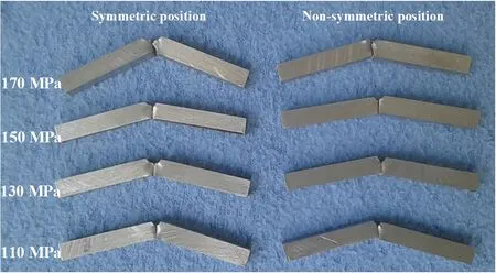
In the same method, Charpy impact test pieces were prepared according to the ASTM E 23-02a standard at room temperature condition with dimension 55 mm ×5 mm ×5 mm and notch with 1 mm depth and 45° angle. Our specimens were picked up in two positions, the first one is symmetric, it takes to the respect of the rotation axis and the interface (Fig.3a), on the other hand, the second one is non-symmetrical with the axis of rotation and symmetrical to the interface, for making the notch head coincide with the center of the welding joint (Fig.3b).

Fig.3Charpyimpacttestpiecesrelatedtoweldingpieces(a)Symmetricposition(b)Non-symmetricposition
Compression tests were carried out at room temperature using MTS 810 material testing system machine with test piece dimensions and extracted from the positions as showed in Fig.4. The test specimens were 4 mm diameter and 6.5 mm length at welding core[9].

Fig.4Compressiontestpiecesrelatedtoweldingpieces
2 Results and discusssion
Obviously, the axial shortening increases with rising friction pressure as shown in Fig.5, it increases remarkably with the interface heat raised and softening of materials following the extruding process under the rotary motion. Conversely, at the low friction the friction heat is not enough to soften the interfacial materials; and the interface heat amount is relatively low due to low heat input. In general, the mechanical properties of a weld are more closely related to the axial shortening rate, where increased axial shortening results better mechanical properties of welding joints which can also be a factor indicative of joint quality[12].

Fig.5Axialshorteningforfrictionweldingpieces
Friction pressure is one of the most important factor that effects on the rate of heat generation, and consequently forging temperature at welding joint interface, this effect is clearly seemed on microstructure of welding joint. Fig.6 illustrates the microstructure of weld center. The application of low friction pressure reveals the lack of bonding[13]due to low input heat and applied forging in low plastic deformation temperature at welding interface (Fig.6a), whereas at high friction pressure application led to increase the area of contact surfaces due to high plastic deformation and dynamic recrystallization resulting from the friction temperature generated, which high bonding occurs at the welding joint (Fig.6b).
The highest hardness value was obtained for the joint with highest friction pressure value[16].The variation of hardness values along the interface shows a decreasing trend when moved from center to periphery (Fig.7), this is because of the existence of the coarse grains as one move from center to the periphery[15]. An increase in the friction pressure caused better joining surfaces where grain refinement and strain hardening occurs and the width of the recrystallized region is mainly affected by the friction pressure[12].
Effect of friction pressure on the ultimate tensile strength (UTS) reveals at Fig.8 where used different diameters 6 and 8 mm, it is showed that the UTS increased obviously with high pressure application[16]and with larger section of the specimen. Thus, explained toward the welding center reduced the input heat and increased the lack of bond which already reduced the tensile strength of welding joint. Obviously, the strain hardening is responsible of increasing UTS due to forge at high temperature level. To obtain high UTS, the friction and upsetting pressures should be as high as possible, while the friction time should be held as short as possible[13].

Fig.6Microstructureofweldingcenter(a) 110MPa(b) 170MPa

Fig.7Hardnessprofileforweldinginterface

Fig.8Tensiletestresultsversusfrictionpressure
Charpy impact tests pieces picked up from friction welding pieces with respect to the axis of rotation. Presently, believed that the location of the sample is important because of the microstructure along the interface is not homogeneous, as an example, for high friction pressure generally the microstructure is characterized by high plastic deformations located at the center related to the other regions (towards the periphery)[19].
The obtained results showed that the position of the specimen influenced on the value of the impact strength for both cases (symmetric and non-symmetric), which that with low friction pressure the mean value of the impact strength decreases and this reducing is greater in the non-symmetric case (Fig.9). Notice, that the friction pressure is controlling the impact strength cause of the last is dictated by the heat content and spread of heat[15]. High friction pressure as has been seen resulted high tensile strength and high impact values[12].

Fig.9Charpyimpacttestsresultsversusfrictionpressure
Compression strength was illustrated in Fig.10, the highest values of yield compression strength at high pressure application due to increase the input heat and complete welded joint. Where at low friction pressure the yield strength reduces especially at 0° causes of low input heat and lack of bond. Noticed, that the AISI 316 under effect of different friction pressure is not totally isotropic.

Fig.10Compressiontestsresultsversusfrictionpressure
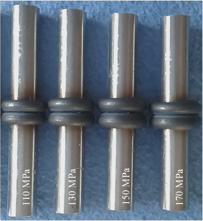
Fig.11 illustrates also the tensile test specimens for 6 mm and 8 mm for different friction pressure, reveals the position of fracture and its profile, thus, Fig.12 shows Charpy impact test pieces in two positions, symmetric and non-symmetric, while Fig.13 demonstrates compression tests pieces with the three positions ( 0°, 45° & 90°).

Fig.11Tensiletestspieces

Fig.12Impacttestspieces
Tensile fracture surface as shown in Fig.14 for 6 mm and 8 mm diameter with 110 and 170 MPa seemed the spherical dimples. Thus, these dimples with different spherical form and dimensions, also showed that the amount of plastic deformation is varied with diameter and pressure applied.

Fig.13Compressiontestspieces
Fig.15 shows also the SEM observation on the fractured surface of the impact test for 110 and 170 MPa. The fracture surface of 110 MPa demonstrated finger print shape resulted from metal flow that occurs cause of nature movement of rotating part against stationary part. Whereas, amount of dimples formation illustrated and clearly observed of shear flow with containing of tiny elongated cavities. While, the fractured surface proves that induced fracture is ductile mode at high friction pressure 170 MPa and a small amount of spherical dimple[13].

Fig.14Tensilefracturesurface(a) 110MPa[6mm] (b) 110MPa[8mm] (c) 170MPa[6mm] (d) 170MPa[8mm]

Fig.15Charpyimpactfracturesurface(a) 110MPa(b) 170MPa
3 Conclusions
(1) As shown from present study, the final properties of the welded joint depend, therefore, on the value of friction pressure.
(2) Concerning the grade AISI 316, high friction pressure level provides more homogeneous joint and properties closest to those of the base metal.
(3) Friction pressure at low level provides properties contrast strongly between the properties of the central part and the remaining joint.
(4) To obtain better strength of welding joint for grade AISI 316 prefer high fiction pressure with shorter time of friction welding to forge at high temperature level.
(5) Weld quality at high friction pressure as determined by microstructure and mechanical tests was good and there were no cracks, lack of bonding or other flaws.
- China Welding的其它文章
- Wear resistance of Zr/WC composite coatings on Cr12MoV steel surface by electric spark deposition
- Effect of electrode morphology on steel/aluminum alloy joint
- Effect of pulse M-Arc frequency on Tri-Arc DE droplet transfer and weld forming
- Thermodynamic study on welding wire design of high nitrogen austenitic stainless steel
- Supervised descent method for weld pool boundary extraction during fiber laser welding process
- Feature extraction of welding defect based on machine vision

