Wear resistance of Zr/WC composite coatings on Cr12MoV steel surface by electric spark deposition
Yu Hua, Long Weimin, Zhong Sujuan 1,, Wang Junzheng and Wei Shizhong
1.Material Science & Engineering Colloge, Henan University of Science Technology; Luo Yang 471003, China;2.Zhengzhou Research Institute of Mechanical Engineering Co.Ltd., Zhengzhou 100044, China;3.National Joint Engineering Research Center for Abrasion Control and Molding of Metal Materials, Luoyang 471003, China
Abstract Zr/WC composite coating was prepared on the surface of Cr12MoV steel by electric spark deposition technology to change its surface properties. The surface and worn surface morphology of the coating were observed using scanning electron microscope. Dry friction and wear tests of the coatings were carried out at room temperature. The results show that the coating is continuous and uniform, and the thickness was about 50-60 μm. The microhardness of the coating surface was highest at 1 140HV200g, which was significantly higher than that of the substrate. The ear tests results show that the wear weight loss, wear volume and wear rate follow the following rules: Cr12MoV>WC coating> Zr/WC composite coating.
Key words Cr12MoV, Zr/WC, electric spark deposition, composite coating, wear resistance
0 Introduction
Electric spark deposition (ESD) is a process of charging and discharging in pulse circuit, which produces spark discharges between working electrodes and strengthened metal surfaces in air or inert gases[1-4]. This can raise instantaneously the temperature at the contact sites, which causes the electrode materials to melt, gasify or plasma[3-6].
In the processes of ESD, electrode materials migrate to the surface of base material at high speed, and metallurgical bonding occurs, which results in the forming of a solid alloy strengthening layer at the surface of base material. The alloy deposits are compactly wrapped on the surface of base material to avoid direct contact with the outside, which greatly improves the properties of the base material surface, while the structure and mechanical properties in its core remain un-changed,thus prolonging the life of the workpiece[7-9].Compared with laser intensification, ion implantation and other technologies, ESD technology can be used not only for surface modification of materials, but also for repair workpieces. Therefore, ESD technology has received more and more attention and application[8-9].
Although strengthening layers such as WC, GoCr and NiCr coatings on the surface of workpieces prepared by ESD technology can significantly improve the hardness and wear resistance of workpieces[6-7], the application of WC coating in surface strengthening is limited because it is thinner (deposition thickness is about 20-50 μm)[2,4,7,9,10]. Based on this, a composite coating was prepared by adding suitable transition layer to improve the thickness of modified layer on the surface of Cr12MoV steel in this study(First deposit a layer of metal Zr on the substrate surface of Cr12MoV, and then continue to deposit WC coating). The interface behavior and wear resistance of coating were studied.
1 Experimental materials and methods
1.1 Selection of transition layer
To improve the thickness of coating layer, a transition layer is often selected when a WC coating on the matrix Cr12MoV steel prepared by using ESD. The following two factors should be considered in the case selecting the transition layer between the coating and matrix. Firstly, the transition layer should have good adhesion with the matrix and WC coating, so that the composite coating can be significantly thickened. Secondly, the thermal expansion coefficient of transition layer material should be between the matrix and WC coating, so as to really play a role of buffer and reduce the thermal residual stress to a certain extent.
Compared with WC,Zr has better physical compatibility with Cr12MoV steel, which is beneficial to improve the quality of coating. The thermal expansion coefficients of matrix, Zr and WC are shown in Table 1. The thermal expansion coefficient of Zr is between matrix and WC. Therefore, Zr was selected as the transition layer material in this study.
Table1Coefficientofthermalexpansionofmaterials

NameMaterialsThermal expansivity(20 ℃)(10-6K-1)SubstrateCr12MoV10.83CoatingWC3.84Transition-layerZr5.78
1.2 Experimental materials and processes
The DZ-4000Ⅲ electric spark deposition machine was used in this study. Zr and WC round rods with a diameter of 3 mm was used as electrodes. The Cr12MoV steel is cut into 16 mm×16 mm×8 mm samples. Before deposition, the surface of the matrix sample and the end of electrode were polished using sand paper to remove the surface oxide layer, and then dried at room temperature after cleaning with acetone. The process parameters are listed in Table 2 during deposition.
Table2Theprocessparameters

SubstrateCoatingProcess of depositionCurrent/AVoltage/VFrequence/HzTime of deposition/minShielding gasDiameter of electrode/mmCr12MoVZr1501 40010Arϕ3WC1501 40010Arϕ3
After deposition, dry friction and wear tests of the coatings were carried out at room temperature using MMS-1G high temperature and high speed pin-disk friction and wear machine. The wear test parameters are shown in Table 3. A YG8 rigid alloy ball with 6 mm diameter was used as the other side of the friction pair. The wear weightlessness of the samples was weighed by AEL-200 electronic analytical balance. The surface and worn surface morphology of the coating were observed using scanning electron microscope (SEM, JSM-560LV). The micro-hardness of coating and substrate were measured by using HVS-1000 microhardness meter.
Table3Weartestparametersatroomtemperature

Load/NRadius/mmRotate speed/(r·min-1)Time/min10560020
2 Experimental results and discussion
2.1 Surface morphology of coating
Fig.1 shows the SEM images of Zr/WC composite coatings surface. A continuous, uniform and compact coating was observed as shown in Fig.1a, where many dense small pits on the surface were observed. Fig.1b shows a high magnification image of A-zone shown in Fig.1a. Sputtering traces and some solidified small particles around the pits were observed. This is because the high temperature instantaneously generated during the electric spark deposition process which resulted in melting of the electrode and the matrix material. At the same time of metallurgical reaction, the melted droplets splashed onto the surface of the matrix and then solidify rapidly.
In the next discharge, the solidified droplets wereremelted again. After numerous remelting stacks, the electric spark coating was finally formed. The droplets spread on the surface of the matrix at a relatively fast speed under the action of large discharge force and thermal explosion. Combining with the morphology analysis, it is considered that the wetting angle was very small and the wetting effect was very good when the droplets spread.
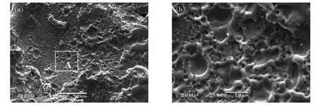
Fig.1Surfacemorphologyofthecoating
(a)SEMimageofcoatingssurface(b)AmplificationofA-zone
2.2 Section morphology of the coating
Fig.2a shows the SEM images of different sections of the Zr/WC composite coating. As shown, the thickness of the Zr/WC composite coating was about 50-60 μm.
The bonding between coating and the matrix were well. A diffusion zone with thickness of 5-10 μm near the interface and few microcrack inside the coating was observed. In the enlarged photograph near the interface between the substrate and the coating as shown in Fig.3a, several bright white areas were observed within the coating. These bright areas were composed of a large number of ultrafine particles.There may be two reasons for the formation of a large number of fine particles inside the coating. Firstly, the instantaneous high temperature of the spark discharge (heating rate up to 107 ℃/s) caused the instantaneous melting of the material in the discharge microzone. Meanwhile, it quickly solidified (cooling speed up to 106 ℃/s) in a very short period of time. These greatly improve the nucleation rate. Secondly, the newly formed coatings on the surface of the substrate were subjected by the discharging force produced by pulse discharge and the mechanical force of rotating electrodes, then plastic deformed during semi-solid solidification. This can also refine the grains[11]. Fig.2b shows the SEM image of different sections of the WC coating. The thickness of the coating was thinner than that of Zr/WC composite coating, which is about 10-35 μm. Several cracks and few pores in the coating were observed. Obviously, the WC coating was not as thick as the Zr/WC composite coating, and the internal quality of the coating was not as good as that of the Zr/WC composite coating.
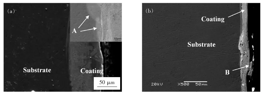
Fig.2SEMimagesofcoatingcross-section
(a)SEMimageofZr/WCcompositecoating(b)SEMimageofWCcoating
2.3 Performance of coating
Fig.3 shows the results of microhardness measurement of coating. As shown, the microhardness value gradually decreased with the increase of the distance to the surface of the coating. The microhardness at the Zr/WC composite coating and the junction with the matrix was 1 140 HV200 gand 900 HV200 g, respectively. The microhardness of the matrix material was about 780 HV200 g. The microhardness of the coating was significantly higher than that of the substrate. Compared with the WC coating, the Zr/WC composite coating included a 30 μm thick transition layer with microhardness of 900 HV200 g.
The high microhardness of both kinds of coating is mainly due to the extremely fast heating and cooling speed during the ESD process, which is equivalent to the quenching treatment to refine the surface tissue, and the distribution of high hardness tungsten carbide hard phase in the sedimentary layer.
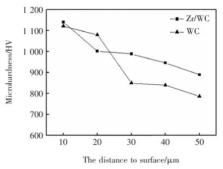
Fig.3Micro-hardnessofcoating
The wear test weightless results are shown in Fig.4. In 20 minutes, the wear of the matrix Cr12MoV, the Zr/WC composite coating and WC coating is 58 mg, 19 mg and 27 mg, respectively. The wear of both coatings was significantly less than that of the matrix Cr12MoV, therein, the wear of the Zr/WC composite coating was less than that of the WC coating.
Fig.5a- Fig.5c show the three-dimensional morphologies of worn surface of WC coating, Zr/WC composite coating and the matrix Cr12MoV after 20 minutes wear under 10N load, respectively. It can be seen that under the same test conditions, three kinds of worn surface have been damaged during wear. As shown, The wear of matrix was the most serious, whereas the wear of Zr/WC composite coating was the lightest. Fig.6a- Fig.6c show the worn trace profile of WC coating, Zr/WC composite coating and the matrix Cr12MoV, respectively. As shown in Fig.6, the worn trace profile widths of WC coating, Zr/WC composite coating and the matrix Cr12MoV were approximately 1 600, 1 450 and 1 950 μm, respectively. For three kinds of worn trace, the depth at their deepest part was 45, 38 and 68 μm, respectively.
Under the same test conditions, the depth and width of the worn trace profile can reflect the wear resistance of a material. The width and depth of worn trace profile of Zr/WC composite coating were smaller among them. This indicates that the wear resistance of the Zr/WC composite coating is largest.

Fig.4Resultsofweartest
In addition, it can be found that the worn trace depth of WC coatings was 45 μm as shown in Fig.6a, which is higher than the maximum thickness of WC coating. This indicates that the WC coating prepared under this wear test condition has failed. The worn trace depth of Zr/WC composite coatings was much lower than the average thickness of the coating. This shows that the wear resistance of the composite coatings prepared by adding Zr transition layer is better than that of WC coating.
The wear volume can more intuitively reflect the loss of material geometry after wear, and the specific wear rate can comprehensively reflect the wear resistance of materials[12]. The wear volume can be determined by the following formula:
WV=S·L
(1)
whereWVis the wear volume,Lis length the worn trace,Sis the cross-sectional area of the worn trace.
Wear rate is defined as:
K=WV/(P·s)
(2)
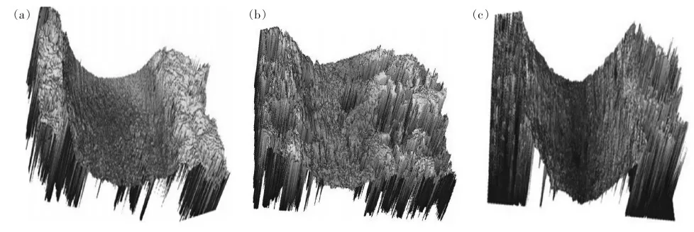
Fig.5Threedimensionaltopographyofwornsurface(a)WCcoating(b)Zr/WCcompositecoating(c)MatrixCr12MoV

Fig.6Profileofworntrace(a)WCcoating(b)Zr/WCcompositecoating(c)MatrixCr12MoV
whereKis the wear rate,WVis the wear volume,Pis the radial load,sis the friction distance, which is the product of the circumference and the number of turns.
The calculated results are shown in Table 4 according to equations (1) and (2). Thewear volume and wear rate follow the following rules: the matrix Cr12 MoV > WC coating > Zr/WC composite coating. Combined with the analysis of friction coefficient and worn surface morphology, under experimental conditions, the coating prepared by ESD can effectively improve the wear resistance of the Cr12MoV. When the prepared WC coating was worn, a large amount of grinding debris was produced to accelerate the surface wear which resulted in serious abrasion and adhesion wear. The residual stress of the composite coating pre-pared by adding transition layer was reduced, and the resistance to plastic deformation was enhanced. This improved its wear resistance.
Table4Wearvolumeandwearrate

Wv /mm3K/(10-6mm3·N-1·mm-1)WC1.403.7Zr/WC1.092.9C12MoV3.9410.8
Fig.7a and Fig.7b show worn surface SEM images of the WC coating after 20 min of wear. A series of scratches along the sliding direction, which was micro-cutting wear morphology characteristics, were observed on the worn surface. Slight bulge phenomenon was also observed on both sides of the furrow, which shows the coating occurred plastic deformation during wear. Moreover, there were a lot of wear debris on the grinding scratch. These shows that the wear of WC coating belongs to typical abrasive wear and adhesive wear[10-11]. Fig.7c,d show worn surface SEM images of the Zr/WC composite coating after 20 min of wear. In comparison with the worn surface of WC coating, the furrows were shallower, the number of particles was also smaller on the worn surface of the Zr/WC composite coating. Moreover, some flaky exfoliation and small pits were observed on the local region of worn surface. This may be caused by the fatigue crack of the coating under alternating stress. Therefore, the wear of Zr/WC composite coating belongs to abrasive wear and fatigue wear.
In general,the plastic deformation of the underlying metal, dislocation generation and accumulation can be reduced, and then the formation, propagation of cracks caused by stress concentration can also be reduced by using a soft transition layer according to the theory reported by Suh[13]. This can delay the failure between the coating and the the matrix. In this study, a valid joining between the matrix Cr12MoV and the coating of WC was achieved by using Zr transition layer. This can prevent the slip and peeling of WC from the matrix. Meanwhile, since the thickness of overall coating layer increased, its wear life was improved because the transition layer itself also has better wear resistance.
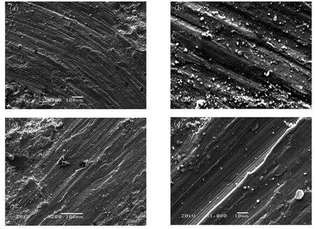
Fig.7WornsurfaceSEMimagesofthecoating(a)WCcoating(lowmagnification) (b)WCcoating(Highmagnification) (c)Zr/WCcoating(lowmagnification) (d)Zr/WCcoating(Highmagnification)
3 Conclusions
(1)A continuous and uniformZr/WC composite coating with a thickness of about 50-60 μm was prepared on the surface of Cr12 MoV steel.
(2)Compared with WC coating, the maximum microhardness of Zr/WC composite coating is higher. The maximum microhardness was 1 140 HV200 g.
(3)The wear, wear volume, and wear rate follow the following rules: the matrix Cr12MoV > WC coating > Zr/WC composite coating.
- China Welding的其它文章
- 3DPMD-Arc-based additive manufacturing with titanium powder as raw material
- Feature extraction of welding defect based on machine vision
- Supervised descent method for weld pool boundary extraction during fiber laser welding process
- Thermodynamic study on welding wire design of high nitrogen austenitic stainless steel
- Effect of pulse M-Arc frequency on Tri-Arc DE droplet transfer and weld forming
- Effect of electrode morphology on steel/aluminum alloy joint

