Seam-tracking based on dynamic trajectory planning for a mobile welding robot
Hong Yuxiang,Du Dong,Pan Jiluan,Li Xiangwen
1.College of Mechanical and Electrical Engineering,China Jiliang University,Hangzhou 310018,China;2.Key Laboratory for Advanced Materials Processing Technology,Ministry of Education,Tsinghua University,Beijing 100084,China;3.Engineering Research Center for Complex Trajectory Machining Technology and Equipment,Ministry of Education,Xiangtan University,Xiangtan 411105,China
Abstract A new seam-tracking method based on dynamic trajectory planning for a mobile welding robot is proposed in order to improve the response lag of the mobile robot and the high frequency oscillation in seam-tracking.By using a front-placed laser-based vision sensor to dynamically extract the location of the weld seam in front of torch,the trend and direction of the weld line is roughly obtained.The robot system autonomously and dynamically performs trajectory planning based on the isometric approximation model.Arc sensor technology is applied to detect the offset during welding process in real time.The dynamic compensation of the weld path is done in combination with the control of the mobile robot and the executive body installed on it.Simulated and experimental results demonstrate that the method effectively increases the stability of welding speed and smoothness of the weld track,and hence the weld formation in curves and corners is improved.
Key words welding automation,seam tracking,mobile robot,dynamic trajectory planning
0 Introduction
Many large components must be welded for use in the fields of energy equipment,heavy machinery and shipbuilding.In recent times,mobile welding robots have become a solution to the large-scale,complex trajectory welds necessary today.These include welds of long distance,large span,large curvature,welds with large corner curves,and polyline welds.The large range of motion capabilities of mobile welding robots has been key to successfully implementing large-scale,complex welds[1-2].The use of welding seam-tracking sensing technology[3]is an inevitable requirement in the development of intelligent mobile welding robots that can compensate for changes in weld position and size due to workpiece processing and assembly errors and welding thermal deformation in real time.
Mobile welding robots are limited by the working stroke of the installed actuator(such as a mechanical arm,X-Y carriage in rectangular coordinate system,etc.).It is necessary to adjust the position and posture of the actuator in coordination with the mobile platform to ensure that the welding torch is aligned with the center of the weld.That is to say,under the cooperative control of the mobile robot and the actuator,automatic tracking of the weld is realized.At present,there are two kinds of weld bead tracking methods commonly used in mobile welding robots:those that use the serial control method and those that use the parallel control method.
(1)The serial control method uses a single type of seamtracking sensor that includes a vision sensor and an arc sensor to detect the welding deviation.The mobile robot body adjusts its position and orientation according to the size and direction of the actual deviation correction adjustment of the actuator.Its accuracy issensitive to the mechanical and electrical inertia of the human system of the mobile machine,which leads to a lag in tracking control.The tracking accuracy of the weld seam can be low,and the quality of the weld seam formation is difficult to guarantee.Particularly in areas where the weld bead is bent or folded,the mobile robot needs to perform a high-angle turning motion to track the weld seam track.It is difficult for the robot to adjust its position and attitude in time;consequently,welding deviation defects are somewhat common in such cases.
(2)The parallel control method uses the actuator to rectify the deviation and adjust the posture of the mobile robot synchronously.A single type of seam-tracking sensor is used to detect the welding deviation.The actual deviation correction of the mobile robot body in the integrated actuator,and the position and orientation adjustment of the sensor,are based on welding deviation information obtained over a sampling adjustment period;this method depends on prior knowledge of the sensor(i.e.,the welding deviation information obtained during the previous sampling adjustment period).With increasing welding distance,the error accumulates,and it is easy to increase the vibration probability,which in turn greatly increases the pose adjustment process of the mobile robot.The welding torch has difficulty tracking the weld path smoothly and stably,especially when weld paths with large curvature changes are involved.Overall,it is difficult to meet the process requirements of quality large-scale welds[4-6].
In view of the problems,an orbit tracking method is proposed based on trajectory dynamic programming to achieve accurate tracking of large-scale complex trajectory welds in mobile robot systems,and thus improve the quality of weld formation.
1 Mobile welding robot
The mobile welding robot system developed for this work,with structure light vision and an arc sensor,is shown in Fig.1.The system is mainly composed of the Pioneer3-AT robot body,4-DOF airborne actuator and its driver,industrial PC,magnetic arc sensing system,structure light sensor,image acquisition card,and motion control card.The Pioneer3-AT robot platform is driven by four wheels in parallel on the same side.Each driving wheel and the driving motor form a speed closed loop,which allows in-situ turning with zero turning radius and accurate speed control.The airborne actuator is installed on the central axis of the connecting line of the same side wheel of the robot platform.The magnetic control arc sensing system controls periodic arc scanning of the welding joint by adding a transverse magnetic field to extract weld position information from the arc energy signal.The structured light sensor uses laser line structured light as the active light source.The area array uses a CCD sensor,which is installed on the front end of the magnetic control arc sensor head(welding torch).The CCD is connected to the image acquisition card to obtain the weld area characteristic image.
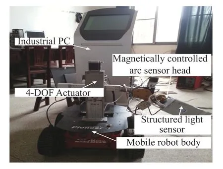
Fig.1 Mobile welding robot system with structured light vision sensor and arc sensor
2 Dynamic planning of mobile welding robot trajectories
2.1 Dynamic fit of the weld trajectory
As shown in Fig.2,the basic Cartesian coordinate systemOxyzof the mobile welding robot,the robot body coordinate systemMxyz,the mobile auxiliary coordinate systemUxyzof rectangular coordinate system,the forward and backward auxiliary coordinate systemVxyz,the left and right auxiliary coordinate systemWxyz,the structured light sensor coordinate systemLxyz,the welding torch coordinate systemCxyz,and the welding seam coordinate systemSxyzwere established.
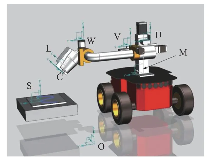
Fig.2 Coordinate system of mobile welding robot
Of these,Oxyzis fixed on the ground,withOas the origin of the coordinates.The robot body has two degrees of freedom.One is the displacement in thexOyplane;the second is the angle of rotation around thez-axis.The robot body is considered as the motion of the body coordinate systemMxyzrelative to the basic Cartesian coordinate systemOxyz.Because the robot body is driven parallel to the side wheels,the robot body model may be simplified to a two-wheel model in two-dimensional plane motion analysis,and tire deformation and longitudinal sliding of the vehicle body are negligible.
The structured light sensor projects the laser light obliquely onto the weld seam,and collects a structured light fringe image containing the features of the weld seam.After image processing and feature extraction,the coordinates of the welding joint features are translated to their representation on the welding torch coordinate systemLxyzand to the robot body coordinate systemMxyz.Depending on the current position of the robot body centroid in the basic Cartesian coordinate system,a set ofNwelding joint features is determined.The base Cartesian coordinate sequenceoGiof theNwelding feature points(xi,yi),(i=1,2,...,N)can then be calculated,whereEiis the deviation from the welding point characteristic pointIto the axis of the magnetron arc sensing head in they-axis direction of the structured light sensor coordinate systemLxyz.Nis given by

whereλis the forward-looking distance of the structured light sensor;vis the welding speed;andTopis the image processing cycle.
The Catmull-Rom cubic interpolation spline[7]was used to fit the collected discrete welding joint feature point position sequence0Gi,and the fitted weld trajectory curveS(x)was derived,The slope of the tangent line onS(x)of each characteristic point on0Giwas solved by the derivative,and the posture matrixPi=[xiyiarctan(ki)](i=1,2,...,N)ofNcharacteristic points of welding groove was obtained.
In the process of seam-tracking,when the structured light sensor does not detect the characteristic point position of the welding joint for several consecutive cycles,the magnetic control arc sensor head drives the structured light sensor to rotate through a fixed angleθxabout thez-axis ofLxyz.The direction of correction in the previous cycle is the same,to ensure that the weld trajectory is always within the field of view of the structured light sensor.θxis calculated from

whereμis the field of view of the structured light sensor.
2.2 Robot trajectory generation
To ensure that the welding speed direction of the mobile welding robot is always consistent with the tangent direction of the trajectory of the proposed weld during the bead tracking process,the motion trajectory of the robot body is dynamically planned on the basis of curve isometric offsets.
The curve isometric offset,ΔE,is such that the threshold σ is compared withthen the thresholdζis compared with ΔE.The motion decision of the robot body is then executed based on the threshold comparison results.The decision set includes continuous-path motion planning(CP,continuous path),car-around-center pivot planning(PS,pivot steering)and point-to-point(PTP)planning,and is calculated from

whereLsis they-coordinate of the welding torch in the airborne actuator coordinate systemUxyz,Lais the maximum working stroke of the airborne actuator in they-axis direction of the airborne actuator coordinate systemUxyz,andLmis the airborne actuator.The pre-set value of the working stroke in they-axis direction of the airborne actuator coordinate systemUxyzdepends on the actual structure to be welded and the size of the airborne actuator.
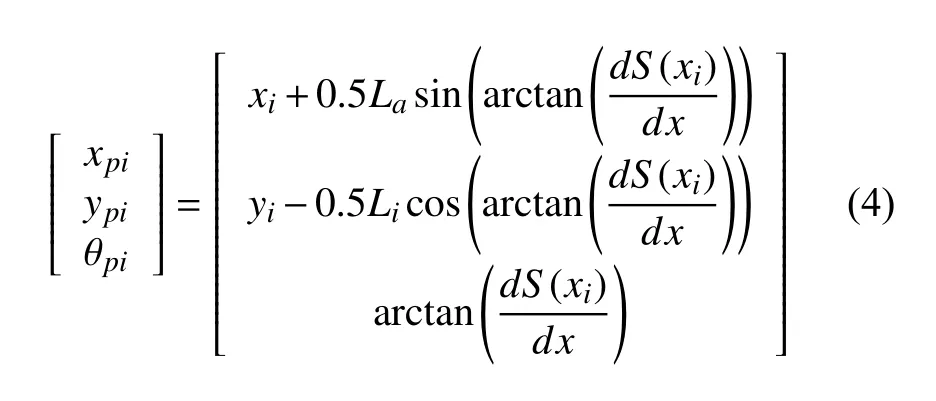
whereLais the length of the horizontal movement of the airborne actuator.
The curve of the Catmull-Rom cubic interpolation spline was used to interpolate discrete path nodes to generate a continuous,smooth robot body motion trajectoryG(x).As shown in Fig.3,the system controls the left-hand and right-hand wheels of the robot using a differential control method based on the kinematics model of the robot body.This enables the robot to complete a walking process along the path nodes on the trajectory and sets the attitude at each discrete moment to be consistent with the tangential direction of the characteristic point of the welding joint on the corresponding weld trajectory,when the robot body is turning.

Fig.3 Motion trajectory generation of a continuous path

(3)When the above conditions are not met,the robot body goes in a straight line and executes the planned pointto-point straight trajectory,moving forward in the current direction for a distanceλat a constant speed.
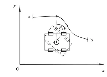
Fig.4 Motion trajectory generation of pivot steering
During posture adjustment of the mobile welding robot along the planned motion trajectory,the magnetron arc sensing system detects the welding deviation information in real time by dynamically compensating the welding trajectory by means of the on-board actuator.
3 Bead tracking test
To verify the validity and reliability of the method described in this paper,a weld bead tracking test of a complex trajectory of a corner joint was performed with the structured light-arc hybrid sensing mobile welding robot.
The test used CO2gas shielded welding.The welding power source was a Fronius TPS4000;the welding process parameters are shown in Table 1.The mobile robot system parameters are shown in Table 2.The test plate material was Q235 steel with a thickness of 5 mm and a joint angle of 120°.The assembly method was as shown in Fig.5a.Point A in the figure was the initial position of the welding.The initial posture C0of the mobile welding robot was[0,-20,π/5]T,and the initial deviation was 0 mm.
Results of the bead tracking test are shown in Fig.5b and the weld details are shown in Fig.5c
The results of the welding bead tracking test showed that the robot body moved smoothly during the tracking process.The welding trajectory basically coincided with the centerline of the weld.The tracking curve was smooth,and the maximum tracking error was±0.4 mm.The welding seam formation was uniform.

Table 1 Welding parameters

Table 2 System parameters of mobile welding robot
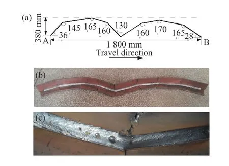
Fig.5 Tracking results of a complex-trajectory weld seam(a)Complex trajectory welding(b)Seam tracking test result(c)Weld detail at chamfer
4 Conclusions
(1)A trajectory dynamic planning model for a mobile welding robot was established.A real-time tracking of a complex trajectory weld was realized on a self-developed mobile welding robot system test platform.The maximum tracking error was±0.4 mm.
(2)A seam-tracking test showed that this method improves the consistency of welding speed and also improves the smoothness of the welding trajectory for complex trajectories.In particular,the welding seam quality at bead bend and corners is markedly improved.
- China Welding的其它文章
- Effect of Ga on microstructure and properties of Sn-Zn-Bi solder for photovoltaic ribbon
- Mechanism analysis of free formation of backing weld by the pulsed MAG-TIG double arc tandem welding
- Cross section scan trace planning based on arc additive manufacturing
- Underwater robot local dry welding system
- Analysis of weld pool vibration characteristics in pulsed gas metal arc welding
- Graphene-coated copper foam interlayer for brazing carbon/carbon composite and niobium

