
Graphene-coated copper foam interlayer for brazing carbon/carbon composite and niobium
2019-04-16 02:12:22WangZeyuBaJinQiJunleiFengJicai
China Welding 2019年4期
Wang Zeyu,Ba Jin,Qi Junlei,Feng Jicai
State Key Laboratory of Advanced Welding and Joining,Harbin Institute of Technology,Harbin 150001,China
Abstract Problems such as poor structural integrity,inhomogeneous dispersion,and agglomeration of graphene in the brazing seam are typically encountered for graphene additives in a brazed joint interface.To resolve these problems,a plasma-enhanced chemical vapor deposition process was employed for in-situ preparation of a high-quality graphene-coated copper(Cu)foam composite interlayer prior to be applied for brazing carbon/carbon composite and niobium.The prepared graphene and the brazed joints were characterized via Raman spectroscopy,scanning electron microscopy,and high-resolution transmission electron microscopy.The results revealed that graphene was evenly distributed in the brazing seam with the help of the Cu foam,which was characterized by interconnected porosity.Simultaneously,the excellent chemical inertia of graphene inhibited the collapse of the Cu foam,based on which the thermal residual stress in the joint was effectively mitigated due to the synergistic reinforcement effect of the Cu foam(with good plastic deformation capacity)and graphene(with extremely low coefficient of linear expansion).This effect led to significant improvement in the average shear strength of the joint.
Key words graphene,composite interlayer,brazing,carbon/carbon composite,residual stress
0 Introduction
Carbon/carbon(C/C)composite is one of the main materials used in the manufacture of hot-end parts comprising space engines and rocket nozzles.This use is motivated by the low density,low thermal expansion coefficient,excellent high temperature mechanical properties,and excellent thermal shock resistance[1]of these materials.In actual production,the brazing of C/C composite materials with hightemperature metals or alloys such as niobium(Nb)is typically required[2-3].Due to the large difference between the thermal expansion coefficients of C/C composite and Nb,a large residual stress will be generated in the brazed joint,leading to poor mechanical properties.Many studies have focused on overcoming this problem by incorporating a soft interlayer or a high-performance reinforcements into the braze seam,thereby alleviating the residual stress and improving the quality of the joint[4-6].The uneven distribution of the interlayer and the limited additive amount of the reinforcements in the brazing seam has,however,hindered further improvements in the joint performance.Therefore,a new type of reinforcement with a uniform distribution with high content in the brazing seam is essential for overcoming these problems.
In recent years,researchers have applied metal foams,possessing three-dimensional porous structure,as interlayers in the field of brazing.The unique network structure prevents uneven dispersion(and easy segregation)of high content reinforcements,thereby alleviating the residual stress of joints and consequently yielding significant improvement in the brazed joints.Zhu et al.[7]reported a nickel foam with high plasticity uniform porosity can be used as the buffer layer for considerably relieving the residual stress of Al2O3/stainless steel brazed joints.Lin et al.[8]found that uniformly dispersed Ti-Cu compounds were formed in the brazing seam through the metallurgical reaction of a Cu foam interlayer with the filler alloy.As a result,the shear strength of the joints improved substantially.However,in the aforementioned studies,the metal foam skeleton reacted with the filler and collapsed,preventing itself from being applied for buffering energy absorption associated with its unique structure.As a new type of carbon nanomaterial,graphene has excellent physical properties,mechanical properties,and chemical inertness,which,therefore,make it an ideal material as joint reinforcement[9].Hu et al.[9]reported a graphene nanoplates reinforced Sn-based composite solders for brazing Cu rods.The results revealed that graphene could inhibits the formation of brittle intermetallic compound layers,refines the interfacial phase grains,and improves the microhardness and shear strength of the joints.However,there was no evidence of reaction between graphene and the solder alloy.Song et al.[10]reported a C/C composite-titanium alloy brazed joint by using a graphene reinforced titanium-based composite solder.It was found that the introduction of graphene significantly reduced the thermal expansion coefficient of the brazing seam and substantially improved the joint mechanical properties via load transfer.However,the current corresponding investigations mainly focus on reduced graphene oxide(RGO)reinforcement,which owns numerous defects and large thickness,and high agglomeration tendency.
In the present work,plasma-enhanced chemical vapor deposition(PECVD)was employed for in situ preparation of vertically-oriented graphene arrays with high content and uniformly distribution on the surface of a Cu foam.Due to the unique three-dimensional network structure of the Cu foam substrate,the difficulty of achieving a high content of uniformly dispersed high-quality graphene was overcomed.Owing to the excellent chemical inertness of graphene,the integrity of the foam skeleton was preserved and hence the residual stresses were significantly mitigated.This method,which is referred to as the synergistic strengthening effect,leads to considerable improvement in the mechanical properties of the brazed joint.
1 Experimental methods
A Cu foam(thickness:0.3 mm,porosity:98%,open-cell rate:≥98%,sample size:5 mm×5 mm×0.3 mm)was applied in this work.The parent material were a C/C composite(density:1.5 g/cm3,sample size:5 mm×5 mm×5 mm)with two-dimensional weave and three-dimensional puncture structure,as well as a 15 mm×10 mm×3 mm asrolled Nb plate.Besides,a Ag-21Cu-4.5Ti alloy foil(thickness:~50 μm)were used as the braze filler.The source gases for graphene growth were methane,hydrogen,and argon.The C/C composite and Nb were grounded with sandpaper and cleaned with alcohol and acetone prior to bedried.Subsequently,the Cu foam was placed in the PECVD equipment.When the pressure was evacuated to<5 Pa,hydrogen(20 sccm)as the reducing gases,and argon(80 sccm),were introduced,then regulated the pressure to 200 Pa.Hydrogen was stopped,argon was relegated to 90 sccm and methane(10 sccm)was introduced when the temperature reached the working temperature.In the meanwhile,the equipment parameter was set as atmosphere pressure:500 Pa,radio frequency(RF)power of deposition system:175 W,RF power frequency:13.56 MHz,under which condition the deposition stage was performed for 60 min.After the deposition was completed,the RF power and heating power were turned off.Eventually,a graphene-coated Cu foam composite interlayer was obtained when the system was cooled down to room temperature.As shown in Fig.1,the braze assembly from bottom to top was Nb/Ag-Cu-Ti foil/composite interlayer/Ag-Cu-Ti foil/C/C composite.The assembled sample was placed in a vacuum brazing furnace.Brazing process was performed under the following conditions:vacuum level:<3×10⁻³Pa,brazing temperature:880 °C,and holding time:10 min.The shear strength of the joints was determined at room temperature.Furthermore,the microstructure of graphene and the brazed joints was evaluated via Raman spectroscopy(Raman),scanning electron microscopy(SEM),and high resolution transmission electron microscopy(HRTEM).

Fig.1 Schematic of the braze assembly
2 Results and discussion
2.1 Morphology and microstructure of graphene

Fig.2 Microstructure of graphene characterized by Raman spectrum,SEM and HRTEM(a)Raman spectrum of graphene(b)Low-magnification SEM image of graphene on Cu foam(c)High-magnification SEM image and(d)HRTEM image of graphene
Fig.2 shows the Raman spectrum,SEM image,and HRTEM image of graphene prepared by means of PECVD on the surface of Cu foam under the aforementioned process parameters.The Raman spectrum of graphene(Fig.2a)consists of three strong peaks,which were located at 1 352 cm-1,1 583 cm-1,and 2 691 cm-1,corresponding to the D,G,and 2D characteristic peaks,respectively.The relative intensity ratio between D peak to G peak(ID/IG)which is associated with the lattice defect,was calculated as~0.528 which is very close to the ID/IGvalue of graphite crystals,indicating the good integrity and sound graphitization of the prepared graphene.In addition,the thickness of graphene can be estimated from the relative intensity ratio of the 2D peak to the G peak(I2D/IG).Fig.2a reveals an I2D/IGof~0.768,suggesting that the prepared graphene consisted of~5-10 atomic layers.The Raman spectrum results exhibits a high-quality few-layer graphene prepared by PECVD process in the present work.
The low-magnification SEM image of graphene on Cu foam is shown in Fig.2b revealing the Cu foam was composed of an unique interconnected porous network structure,which was well preserved after graphene growth.To further investigate the morphology of the prepared graphene,high magnification SEM was carried out,which disclose the top and side view of the vertically-oriented few-layer graphene sheets are quite thin and are characterized by very uniform dispersion without agglomeration,as shown in Fig.2c.Previous studies have reported that graphene prepared by PECVD method will form a complete coverage as buffer layer on the surface of Cu foam[11].The above results shows that the Cu foam has been fully coated by the insitu prepared high-quality few-layer graphene,which is conducive to yield an even distribution of graphene in the braze seam with the help of the unique three-dimensional skeleton structure of the Cu foam.
Fig.2d shows the HRTEM image of graphene,from which it is obvious that the graphene film is thin,transparent,and uniform in a large selected area(50 nm).Approximately 5-10 carbon atomic layers were observed at the boundary and the lattice spacing is~0.34 nm,which matches the one of graphite.
2.2 Microstructure of brazed joints
The interfacial microstructure of C/C composite-Nb joints brazed at 880 °C for 10 min without interlayer,with pure Cu foam interlayer and with the graphene-coated Cu foam composite interlayer are shown in Fig.3a-c.Table 1 shows the chemical composition of the corresponding characteristic regions shown in Fig.3 by EDS analysis.Region"A" with eutectic characteristics is composed of Ag(s,s)and Cu(s,s).Similarly,the TiC reaction layer of "B" was formed at the interface in between the C/C composite and the braze seam.Ti-Cu compound particles comprise the continuous wave-like dark gray phase of "C".When the pure Cu foam interlayer was used,the dark gray bulk phase of "D" was almost entirely composed of Cu(s,s).Additionally,the continuous wave-like phase “E” is still detected as Ti-Cu compound,which is,however,disappeared when using the composite interlayer for brazing.
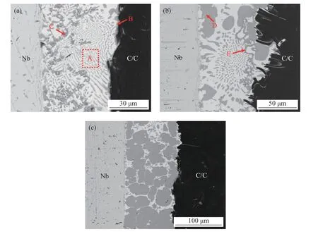
Fig.3 Interfacial microstructures of the C/C composite-Nb joints brazed(a)Without interlayer,with(b)Pure Cu foam and(c)Composite interlayer.
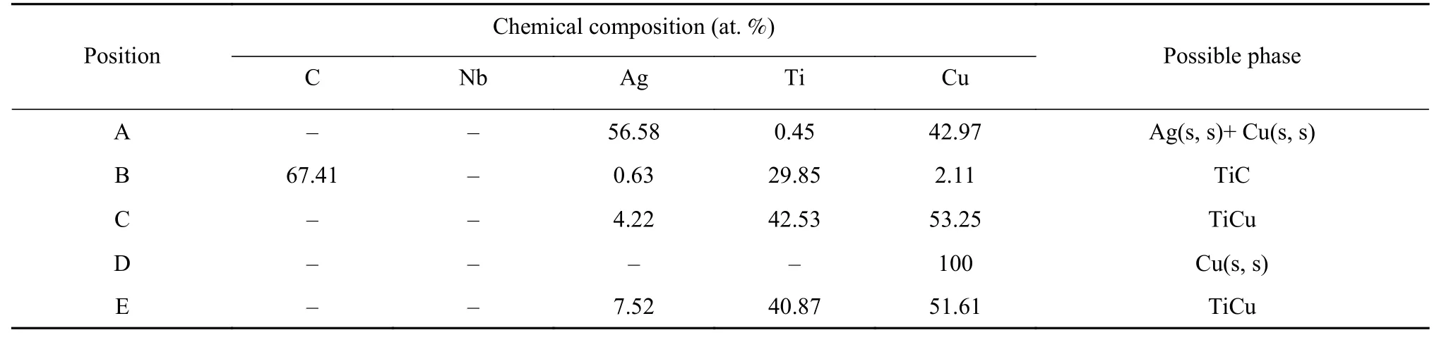
Table 1 EDS compositional results of the joint interface
The results of the joint brazed without interlayer show the braze seam was well bonded with the parent materials(C/C composite and Nb).As for the Nb/braze seam interface,there exists a sound diffusion layer without any reaction products.A TiC reaction layer with the thickness of~2 μm was formed at the interface in between the C/C composite and the braze seam.The interfacial microstructure at the joint was mainly composed of the Ag(s,s)+Cu(s,s)eutectic microstructure.with the formation of continuously formed wave-like Ti-Cu compound particles.As for the joint brazed with the Cu foam interlayer,consumption of elemental Ti by Cu-Ti reaction led to inevitable reduction in the thickness of the TiC reaction layer from~2 μm to~0.5 μm.In addition,the introduction of Cu foam increase the content of Cu(s,s)formed in the brazing seam,which to some extent enhance the plasticity of the joint.However the Cu(s,s)phases were unevenly dispersed in the braze seam.In comparison,when applying the composite interlayer,the interfacial microstructure changed significantly.In details,the bulk Cu(s,s)pieces,derived from the Cu foam skeleton were evenly distributed in the braze seam,resulting from the protection of graphene due to its excellent chemical inertness.Namely,the Cu foam skeleton was well preserved by preventing it from the severe chemical reaction with the filler,thereby enhancing the role of Cu foam in mitigating the residual stress[12].In addition,the width of the braze seam reached~40 μm,which is higher than that of the joint brazed with a pure Cu foam interlayer.Note that no wavelike brittle phases were formed from the Ti-Cu reaction under the protection of graphene on the Cu foam surface..
2.3 Mechanical properties of brazed joints
Fig.4 shows the shear strength of the C/C composites-Nb joints brazed without interlayer and with pure Cu foam as well as with the composite interlayer.The results reveal that the shear strength of the brazed joint can be significantly improved by incorporating an interlayer into the brazing seam.Brazing without an interlayer led to large residual stress in the brazed joint,which is resulted from the large difference between the thermal expansion coefficient of the parent materials and the braze seam.Furthermore,the uneven distribution of brittle compounds products could deteriorate the joint by increasing the stress concentration of the joint under load.These factors have considerable impact on the brittle TiC reaction layer[13].As a consequence,the average shear strength of the joint was only 12.3 MPa.When using pure Cu foam for brazing,the shear strength of the C/C composite-Nb joint was nearly doubled to 22.8 MPa.Although the Cu foam collapsed through reacting with the filler,the good plasticityof Cu(s,s)may play a role in alleviating(to some extent)the residual stress.In comparison,as for the joint brazed with the graphene-coated Cu foam composite interlayer,the braze filler exhibited excellent wettability on the graphene surface without defects formed in the braze seam.What is more important is that the composite interlayer played a key role in residual-stress absorption through plastic deformation during the brazing process.Besides,graphene,possessing extremely low thermal expansion coefficient,was evenly distributed in the braze seam with the help of the Cu foam skeleton,which also contributed to relieving the residual stress of the joint to some extent.Through the synergistic strengthening effect from Cu foam and graphene,the average shear strength of the joint reached 43.2 MPa,which is~240% higher than that of the joint brazed without an interlayer.
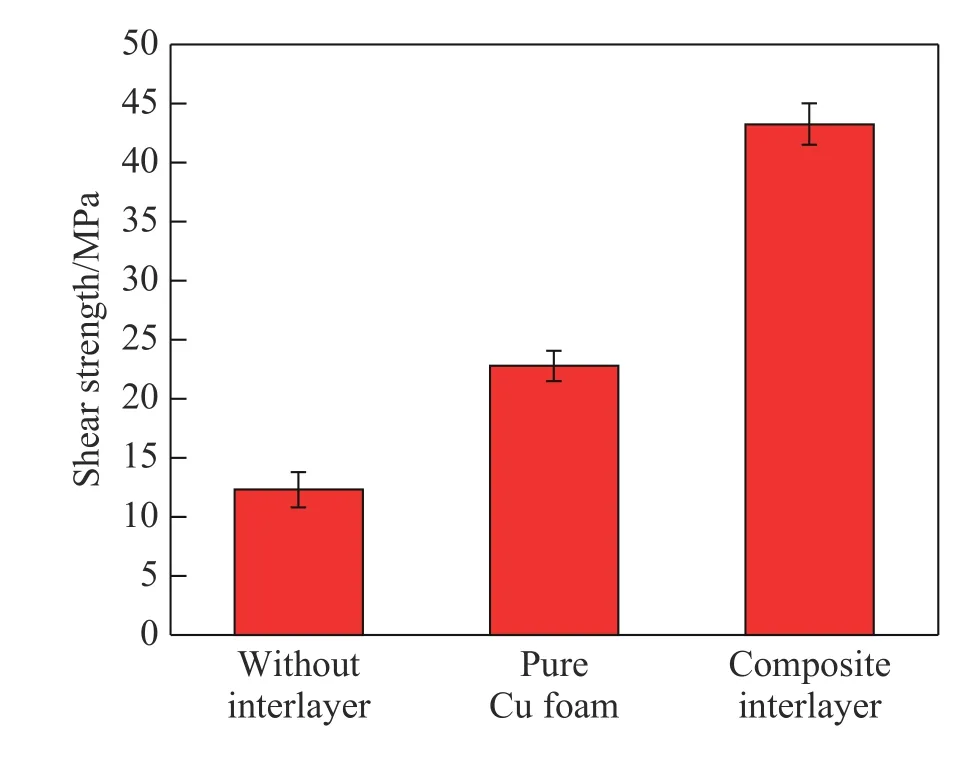
Fig.4 Shear strength of the C/C-Nb brazed joints.
3 Conclusions
(1)By carrying out the PECVD method,the fabrication of a graphene-reinforced foam Cu composite interlayer was realized by in-situgraphene growth on the surface of a Cu foam.In this way,the problem of segregation and agglomeration of graphene additives in the braze seam has been well resolved.
(2)By applying the graphene-coated Cu foam composite interlayer,the Cu foam and graphene exerted synergistic strengthening effect,which is conducive to considerably mitigate the residual stress of the joint.
(3)When using the graphene-coated Cu foam composite as interlayer,a brazing temperature of 880 °C and holding time of 10 min yielded a robust C/C composite-Nb joint with an average shear strength of 43.2 MPa at room temperature.
- China Welding的其它文章
- Fabrication of in-situ synthesized ceramic reinforced Ni-based alloy composite coatings by reactive braze coating processing
- Electron beam welding of SiCp/2024 and 2219 aluminum alloy
- Seam-tracking based on dynamic trajectory planning for a mobile welding robot
- Combine S-N curve and fracture mechanics for fatigue life analysis of welded structures
- Analysis of weld pool vibration characteristics in pulsed gas metal arc welding
- Underwater robot local dry welding system