Combine S-N curve and fracture mechanics for fatigue life analysis of welded structures
Wei Guoqian,Odsuren Ochbileg,Yue Xudong,Dang Zhang
1.School of Machinery and Automation,Wuhan University of Science and Technology,Wuhan 430081,China;2.Hubei Key Laboratory of Mechanical Transmission and Manufacturing Engineering,Wuhan University of Science and Technology,Wuhan 430081,China
Abstract Based on the evolution of fatigue cracks in welded structures,the fatigue life of welded structures was defined as the sum of the crack initiation life Ni and the crack propagation life Np.Correspondingly,a fatigue-life analysis method combining S-N curves and fracture mechanics theory was proposed.The equivalent structural stress method and the lower 99% boundary of the master S-N curve were used to evaluate Ni,and cracks at the end of the initiation stage were considered as semi-elliptical surface cracks.Moreover,Paris equation and the stress intensity factor range of the cracks were used to evaluate Np.Furthermore,the fatigue test results obtained from the running girder of cranes were used as a reference for comparison and verification of the results.The results revealed that the equivalent structural stress is a good indicator for the crack initiation behavior of complex welded structures.In addition,the predicted fatigue life corresponded closely to the testing life.
Key words welded structures,fatigue life,equivalent structural stress,S-N curve,fracture mechanics
0 Introduction
Welding,which represents an economic and effective means of connecting metallic components,is widely used in machinery,transportation,construction,pressure vessels,and other fields.Welded structures subjected to cyclic loading fail mainly via fatigue fracture,and the life prediction of these structures is always an important problem in engineering.
Common fatigue prediction methods include nominal stress method,hot spot stress method,and structural stress method[1-4].These methods,which are based on S-N curves associated with specific types of welded joints,neglect the influence of the weld detail geometry,especially the initial crack state.Based on Taylor critical distance theory,Peng et al[5]introduced the fatigue notch coefficient of welded joints.The influence of the parameters employed in hot spot stress method on the fatigue prediction of welded joints was revealed.In addition,based on fracture mechanics theory,some scholars defined the life of a welded structure as the number of cycles from the initiation of a crack to the point where the critical size is reached.Paris model was used to perform the integration computing to determine the residual life.The above descriptions of crack initiation and short crack fracture behavior are of several shortcomings.Firstly,different assumptions about the initial crack length of the weld introduced considerable uncertainty into fatigue-life prediction[6].Xu et al[7].used Monte Carlo method to estimate the fatigue reliability of the welded box girders of cranes.The test results revealed an average value of 0.25 mm(standard deviation:0.48 mm)for the initial crack length of the welded box girders of cranes.Secondly,Paris model is only valid for the long crack stage,and the results deviate from the real crack propagation behavior of the welded structures when the life is estimated only by using this model.Chapetti et al[8]considered the different growth rates of short cracks and long cracks,and proposed a two-stage fracture mechanics assessment method integrating short and long cracks.Tang[9]proposed a unified cross-scale crack model and its solution algorithm by using the strain energy density factor as the control parameter.
Welded joints have been extensively investigated.However,in engineering practice,the structure and stress state as well as the mode of crack initiation and propagation of welded structures are more complex than those of other type joints.Fatigue-life prediction via the aforementioned methods is very difficult.Therefore,a new method of fatigue-life analysis is proposed for welded structures.This method combines the S-N curve and fracture mechanics theory for considering both the crack initiation life and crack growth life.
1 Evolution process of fatigue cracks in welded structure
Generally,the fatigue evolution process of metallic materials includes three stages:crack initiation,stable propagation,and unstable propagation(an extremely short stage).Therefore,the fatigue lifeNtis often defined as the sum of the crack initiation lifeNiand the crack propagation lifeNp.Consider the inevitable occurrence of welding defects in welded structures,Niis generally considered very short or even non-existent,and the fatigue lifeNof welded structures is often approximately equal toNp.Some studies have shown that even if welding defects(except for crack defects)are present in the welded structure,Niwill still account for a considerable fraction of the entire fatigue life.This is especially evident in high cycle fatigue,soNiis long enough and cannot be neglected.Generally,welded structures in practical engineering should meet the corresponding welding quality requirements in industry.Hence,these structures can be considered free of crack defects,and their fatigue life should includeNiandNp.
Fig.1 describes the main stages in the fatigue crack evolution process of a welded structure(stage 1:crack initiation stage,stage 2:micro-crack growth stage,and stage 3:macro-crack growth stage).In the first stage,the weld geometry,weld defects,microstructure,residual stress,and other factors lead to an intense stress concentration in the weld toe.Multiple micro-cracks,which are difficult to be observed and defined,are initially formed on the weld toe surface.In the second stage,micro-crack aggregation results in the formation of a main crack that propagates to a macroscopic surface crack,which can be detected via engineering methods.In the third stage,this surface crack propagates along the depth of the plate thickness,eventually penetrating the plate and leading to failure of the welded structure.The maximum principal stress at the crack tip may be the main driving force for crack growth in this stage,and promotes the crack growing in the plate.
A strict boundary is lacking from the above three stages,the crack size and corresponding life span are uncertain,and the main control parameters differ among the stages.Generally,the stress concentration factorKthas a considerable influence on the crack initiation stage and micro-crack propagation stage.Moreover,the macro-crack propagation stage is mainly controlled by the stress intensity factorK,while the final fracture stage is controlled by the fracture toughnessKICof the base metal or the actual structures.

Fig.1 Crack evolution in welded structures
2 Fatigue-life prediction model of welded structure
2.1 Fatigue life composition of welded structure
The crack initiation stage and the micro-crack propagation stage of the welded structure are greatly affected by the microstructure and the structure composition of the weld.Effective detection methods and descriptive models are currently lacking.Methods for accurately determining the crack size is also lacking.Micro-cracks can become macrocracks that can be detected in engineering practice at the end of these two stages.The sum of the two stages is taken as the crack initiation lifeNi.The macro-crack growth life is recorded asNpand can be calculated by using Paris model with the actual growth state.Hence,the total service lifeNtof the welded structure is calculated as follows:

2.2 Prediction of fatigue crack initiation life
Fatigue tests were performed on specific welded joints.Various standards and codes(e.g.,AASHTO,IIW,BS7608,GB50017)based on these test results have provided a lot of S-N curve series that apply to specific welded joints.During the design process,the life calculated from the S-N curve is generally considered as the number of cycles associated with crack initiation in the welded structure.Although explicit stipulation of the corresponding crack state is lacking from various standards and codes,in practice,this stage is often regarded as the crack initiation state,for the purpose of conservation.
Dong et al[10]used the equivalent structural stress method to evaluate the fatigue test results of more than 2000 different weldments,and obtained a main S-N curve.Various crack states were represented in the curve.For example,some states corresponded to the micro-crack growth stage,and some states corresponded to crack propagating into the plate thickness and entering the macro-crack growth stage.Some other states were undetermined,but all the test results lie above the lower limit curve with 99% probability.Therefore,the equivalent structural stress and the 99%lower limit S-N curve are proper to describe the crack initiation life of welded structures.The equivalent structural stress curve is described by the following expression:

where Δσessis the equivalent structural stress range.
2.3 Prediction of fatigue crack growth life
In order to determine the fatigue crack growth life,the crack at the end of the initiation stage is defined as a semielliptical surface crack.The crack depthaand width 2ccan be obtained via SEM analysis for fatigue fracture or by referring to the relevant literature.The process of fatigue crack growth can be described by Paris model,which is governed by the following expression:

where,Candmare material constants;ΔKis the stress intensity factor range.The ΔKof a semi-elliptical surface crack can be determined from:

where Δσ,Fs,FT,FE,andFGare the characteristic stress range at the crack tip,free surface correction coefficient,finite plate thickness or width correction coefficient,crack shape correction coefficient,and geometric correction coefficient,respectively.Fs,FT,FE,andFGare given as follows:

wheretis the thickness of the base metal plate,σiis the bending stress along the thickness directionyi(0≤yi≤t),andσis the surface bending stress.
After the surface crack propagates through the thickness of the plate,this crack becomes a through crack.The corresponding ΔKis calculated as follows:

3 Example analysis
3.1 Description of problems
In order to verify the life prediction model of the welded structure in this work,the fatigue test results of the crane running girders in reference [11] are compared and verified.The specimens are welded I-girders with arc transition at both ends.In addition,the material of the specimens is Q345,with yield strength of 345 MPa and weld height of 8 mm(see Fig.2 for the size of the test specimens).
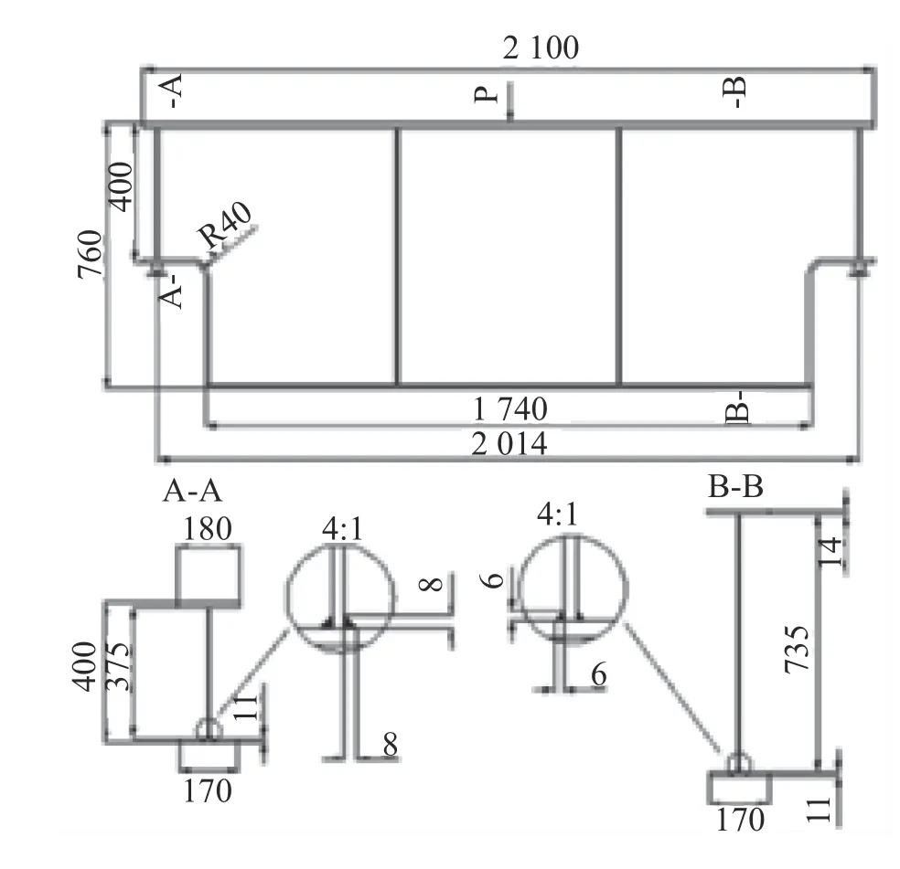
Fig.2 Details of the test specimens from reference[11]
In reference [11],the fatigue tests on five girders were performed by means of three-point bending test.The cyclic load was applied to the middle of the span or 1/3 of the span in the form of a concentrated force,and the stress ratioRis 0.1.The maximum force and acting position are shown in Table 1.

Table 1 Loads applied during the fatigue tests
The test results show that fatigue failure occurs in the variable section at both ends of the girder loaded in the middle span.However,for the specimen loaded at 1/3 span,failure occurs only at the end near the load.Furthermore,all cracks appear at the weld toe of the arc section.Two typical propagation modes are observed:along the weld curve(Mode 1)and in the base metal(Mode 2).In reference [11],the number of load cycles is defined as the nominal life of the structure when the crack length reaches 20 mm,the test results of the present study are shown in Table 2.
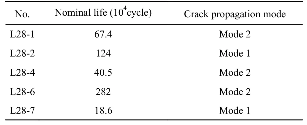
Table 2 Nominal fatigue life of each test specimen
3.2 Location analysis of fatigue crack initiation
The finite element model of the specimen shown in Fig.3 is established by using the finite element preprocessing software Hypermesh12.0.The calculation of the equivalent structural stress is performed by extracting the node force at the weld toe.Therefore,a layer of elements is built at the bending side and the web side,in strict accordance with the weld height(mesh size:8 mm).As shown in Fig.3,the shell element is constructed between the two layers for simulation of the weld.A global element size of 10 mm is employed for the other parts of the model,and 42434 elements in total are used in the model.
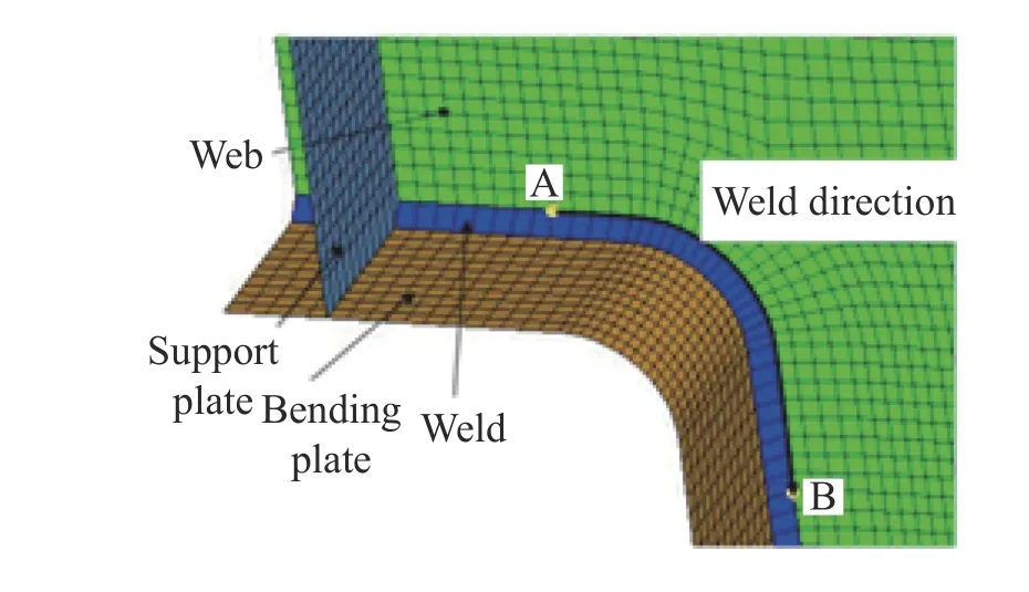
Fig.3 FEA mesh of transition arc area
The finite element software ANSYS12.0 is used to determine the mechanical parameters of the weld toe at the transition arc of the specimens.This software is also used to extract the node forces of each element between points A and B along the weld toe curve on the web,as shown in Fig.3.Afterward,the equivalent structural stress σessof the weld toe is obtained from the construction equation of this stress.The σesscurves for five specimens are shown in Fig.4.The five vertical lines in the figure correspond to:the starting point A of the weld section to be investigated,intersection of the horizontal section and the arc section,midpoint of the arc section,intersection of the arc section and the vertical section,and the ending point B.Different load conditions yield the same distribution pattern of the equivalent structural stress along the weld,but the amplitude of the stress changes.Therefore,the distribution of the equivalent structuralstress is mainly related to the structure geometry,and the stress amplitude is mainly affected by the load magnitude and location.
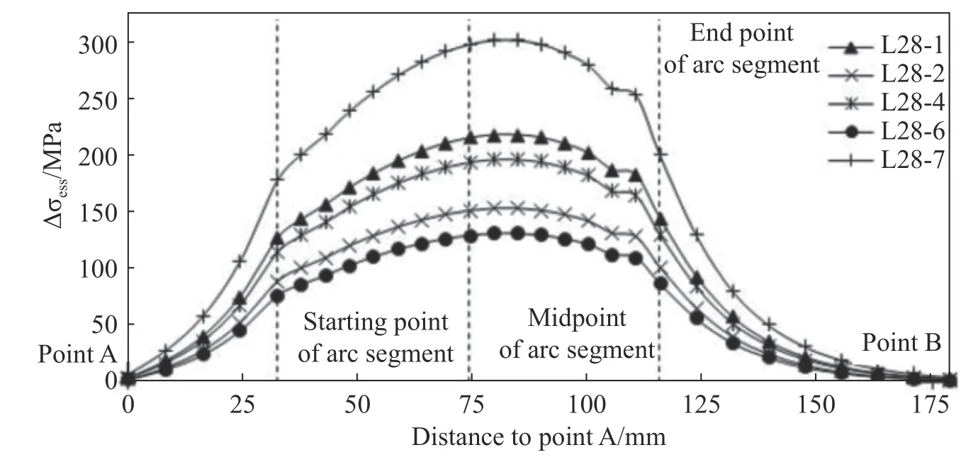
Fig.4 Equivalence structural stress range curves of weld toe at web side
The maximum principal stress range curve and equivalent structural stress range curve corresponding to the specimen L28-7 are compared in Fig.5.As shown in the figure,the curve of the maximum principal stress range is smooth and continuous,and is relatively gentle for the arc section of the weld.Two fewer significant extremum occur near the two ends of the arc(compared with other regions of the arc).The stress range outside the arc section is still greater than 100 MPa,which is extremely high.The equivalent structural stress range curve is quite broad for the arc section of the weld and an obvious extremum occurs in the middle part.The equivalent structural stress range at the weld toe outside the arc section decreases sharply,and is close to zero at point A and point B.Consider the description of cracks in reference [11] and the fatigue cracks observed for similar structures in engineering practice,the fatigue fatal points associated with this type of structures are clustered in the middle of the arc section of the weld,and only a few cracks occur outside the arc section.From this point of view,the equivalent structural stress curve reflects the above characteristics better than the maximum principal stress curve.Therefore,this curve can be used as the control parameter of fatigue crack initiation occurring in this type of structure.
3.3 Analysis of the fatigue life
Based on the maximum stress range of the equivalent structural stress shown in Fig.5,the fatigue life and the crack initiation life(Ni)are determined from Eq.(2).The crack is a semi-elliptical surface crack with the initial surface crack width 2c0of 0.2 mm,which is in accordance with the previous study[6].Assuming that the ratioa/2c,i.e.,the ratio of the crack depth to the crack width remains constant at 0.375,the initial crack deptha0is 0.093 75 mm.
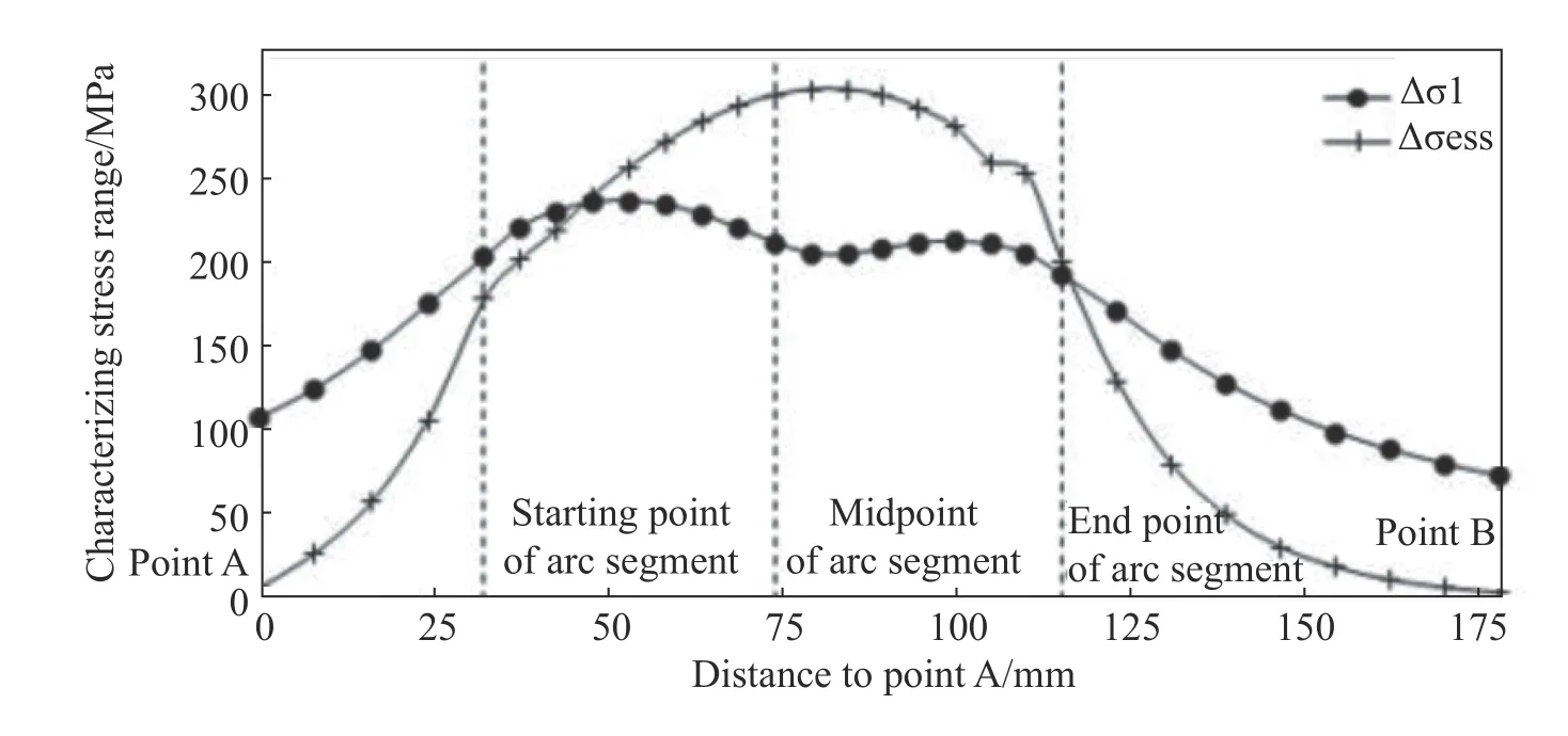
Fig.5 Stress range curves of weld toe at web side

Table 3 Evaluating fatigue life of test specimens
The crack propagation lifeNpis determined from Eqs.(3)-(8).The crack propagation life is divided into two substages,where:(1)the initial surface crack propagates along the thickness direction of the web to 78% of the plate thickness[12].At that time,the web is no longer able to resist this propagation,and the crack is considered as a through crack(crack deptha1=6.24 mm,crack width 2c1=16.64 mm);(2)The through crack propagates along the direction of the weld until a crack length ofac=20 mm is reached.The crack width 2c1from the previous stage serves as the initial crack length of the present stage.For the specimen material,Q345,C=2.19×10⁻¹³andm=3.33[12]are taken for the aforementioned two stages.Compared with the maximum principal stress,the equivalent structural stress provides a better description of the local stress state at the weld toe and,hence,the stress intensity factor range(ΔK)is calculated from this stress.The ΔKvalues associated with crack propagation along the web thickness and surface directions are calculated from Eqs.(4)and(9),respectively.The fatigue life of each specimen is shown in Table 3.
As shown in Table 3,the crack initiation life and the crack growth life in the first stage account for~50% of the total life.The results show that the crack initiation and the initial surface crack propagation along the thickness direction represent the two main stages of the crack evolution process of the welded structure.Therefore,fatigue-life analysis using the S-N curve only or the LEFM method only yields unsatisfactory results.The crack growth life in the second stage is very short and can be ignored.
Except for L28-4,the predicted life of each specimen corresponds closely to the testing life,as shown in Table 4 and Fig.6(the data are plotted in the double logarithm coordinate system).The testing life of each specimen is distributed on both sides of the regression line corresponding to the predicted life,with a large deviation occurring for L28-4.This results mainly from the fact that the density of processing defects in the specimen exceed the standard.In addition,Fig.6 also shows that each testing life lies above the S-N curve corresponding to the 99% lower limit.Therefore,even for poor welding quality of the welded structure,the equivalent structural stress can still be used as a reliablecrack initiation control parameter.
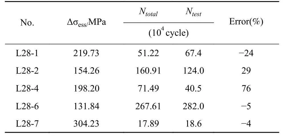
Table 4 Comparison of fatigue life of test specimen
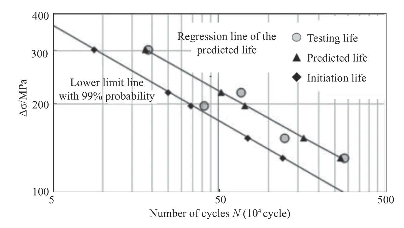
Fig.6 Comparison of fatigue life
4 Conclusions
(1)The crack initiation process will account for a considerable portion of the entire fatigue evolution process occurring in welded structures that meet the welding quality requirements in industry.The fatigue life of welded structures should consist of two components:the crack initiation life and the crack propagation life.
(2)Compared with the maximum principal stress,the equivalent structural stress provides a better description of the stress state at the weld toe and is more capable of identifying the crack initiation position.Therefore,the equivalent structural stress can be used as a control parameter for crack initiation in complex welded structures.
(3)The equivalent structural stress method and 99%lower limit main S-N curve are used to calculate the crack initiation life.Furthermore,the Paris crack growth model and stress intensity factor of a semi-elliptical surface crack are used to calculate the crack propagation life.The calculation results correspond closely to the test results.
- China Welding的其它文章
- Effect of Ga on microstructure and properties of Sn-Zn-Bi solder for photovoltaic ribbon
- Mechanism analysis of free formation of backing weld by the pulsed MAG-TIG double arc tandem welding
- Cross section scan trace planning based on arc additive manufacturing
- Underwater robot local dry welding system
- Analysis of weld pool vibration characteristics in pulsed gas metal arc welding
- Graphene-coated copper foam interlayer for brazing carbon/carbon composite and niobium

