Effects of Terminal Groups in Third Components on Performance of Organic Solar Cells
2019-03-22 06:34XUEPeiyaoZHANGJunxiangXINJingmingRECHJeromyLITengfeiMENGKaixinWANGJiayuMAWeiYOUWeiMARDERSethHANRayZHANXiaowei
物理化学学报 2019年3期
XUE Peiyao , ZHANG Junxiang , XIN Jingming , RECH Jeromy , LI Tengfei , MENG Kaixin ,WANG Jiayu , MA Wei , YOU Wei , MARDER Seth R. , HAN Ray P. S. ,*, ZHAN Xiaowei ,*
1Department of Materials Science and Engineering, College of Engineering, Key Laboratory of Polymer Chemistry and Physics of Ministry of Education, Peking University, Beijing 100871, P. R. China.
2 Center for Organic Photonics and Electronics, School of Chemistry and Biochemistry, Georgia Institute of Technology, Atlanta,GA 30332-0400, USA.
3 State Key Laboratory for Mechanical Behavior of Materials, Xi’an Jiaotong University, Xi’an 710049, P. R. China.
4 Department of Chemistry, University of North Carolina at Chapel Hill, Chapel Hill, NC 27599-3290, USA.
Abstract: Ternary blends have been considered as an effective approach to improve power conversion efficiency (PCE) of organic solar cells (OSCs). Among them, the fullerene-containing ternary OSCs have been studied extensively, and their PCEs are as high as over 14%. However, all non-fullerene acceptor ternary OSCs are still limited by their relatively lower PCEs. In this work, we used wide-bandgap benzodithiophene-difluorobenzotriazole copolymer FTAZ as the donor, low-bandgap fused-ring electron acceptor (FREA), fused tris(thienothiophene) end-capped by fluorinated 1,1-dicyanomethylene-3-indanone (FOIC)as acceptor, and two medium-bandgap FREAs, indaceno-dithiophene endcapped by 1,1-dicyanomethylene-3-indanone (IDT-IC) and indacenodithiophene end-capped by 1,1-dicyanomethylene-3-benzoindanone (IDT-NC), as the third components to fabricate the ternary blends FTAZ:FOIC:IDT-IC and FTAZ:FOIC:IDT-NC, and investigated the effects of the third components on the performance of ternary OSCs. Both IDT-IC and IDT-NC are based on the same indacenodithiophene core but contain different terminal groups (phenyl and naphthyl). Relative to IDT-IC with phenyl terminal groups, IDT-NC with naphthyl terminal groups has extended π-conjugation, down-shifted lowest unoccupied molecular orbital (LUMO), red-shifted absorption and higher electron mobility. The binary devices based on the FTAZ:FOIC, FTAZ:IDT-IC and FTAZ:IDT-NC blends exhibit PCEs of 9.73%, 7.48% and 7.68%, respectively. Compared with corresponding binary devices, both ternary devices based on FTAZ:FOIC:IDT-IC and FTAZ:FOIC:IDT-NC exhibit better photovoltaic performances. When the IDT-IC weight ratio in acceptors is 50%, the FTAZ:FOIC:IDT-IC ternary devices exhibit the best PCE of 11.2%. The ternary-blend OSCs yield simultaneously improved open-circuit voltage (VOC), short-circuit current density (JSC) and fill factor (FF) compared with the binary devices based on FTAZ:FOIC. The higher VOC is attributed to the higher LUMO energy level of IDT-IC compared with FOIC. The improved JSC is attributed to the complementary absorption of FOIC and IDT-IC. The introduction of IDT-IC improves blend morphology and charge transport, leading to higher FF. The FTAZ:FOIC:IDT-NC system yields a higher PCE of 10.4% relative to the binary devices based on FTAZ:FOIC as the active layer. However, the PCE of the FTAZ:FOIC:IDT-NC-based ternary devices is lower than that of the FTAZ:FOIC:IDT-IC-based ternary devices.Compared with the binary devices based on FTAZ:FOIC, in FTAZ:FOIC:IDT-NC-based ternary devices, as the ratio of the third component increases, the VOC increases due to the higher LUMO energy level of IDT-NC, the FF increases due to optimized morphology and improved charge transport, while the JSC decreases due to the overlapped absorption of FOIC and IDT-NC. The terminal groups in the third components affect the performance of the ternary OSCs. The lower LUMO energy level of IDT-NC is responsible for the lower VOC of the FTAZ:FOIC:IDT-NC devices. The red-shifted absorption of IDT-NC leads to the overlapping of the absorption spectra of IDT-NC and FOIC and lower JSC. On the other hand,replacing the phenyl terminal groups by the naphthyl terminal groups influences the π-π packing and charge transport.The FTAZ:FOIC:IDT-NC blend exhibits higher electron mobility and more balanced charge transport than FTAZ:FOIC:IDT-IC, leading to a higher FF.
Key Words: Fused-ring electron acceptor; Non-fullerene acceptor; Organic solar cell; Terminal-group effect;Ternary blend
1 lntroduction
Organic solar cells (OSCs) present some merits, such as easy processing, low cost, light weight, semitransparency and flexibility, and have potential applications in wearable electronic devices, aesthetic windows, building-integrated photovoltaics and so on1-5. Most high-performance OSCs are based on solution-processed bulk heterojunction (BHJ)structure, which is composed of the mixing network of electron donor (D) and electron acceptor (A)6,7. Fullerene electron acceptors and their derivatives (e.g., phenyl-C61-butyric acid methyl ester (PC61BM) and phenyl-C71-butyric acid methyl ester (PC71BM)) have been widely used owing to their outstanding properties such as high electron mobility and isotropic charge transport8,9. Nevertheless, the fullerene-based acceptors suffer from some inherent shortcomings, such as poor absorption in the visible region, limited energy level tunability and instable morphology10,11. So many efforts have been dedicated to developing non-fullerene acceptors (NFAs), such as rylene diimide derivatives12-18and fused-ring electron acceptors (FREAs)19-38. Compared with fullerenes, NFAs demonstrate some advantages, such as tunable molecular energy levels, enhanced optical absorption in visible and near-infrared (NIR) region, and easy synthesis. As a result, they are emerging the most promising acceptors for high performance OSCs.
In order to further improve the photovoltaic property, many other approaches have been examined. For example, ternary blends have been considered as an effective approach to improve power conversion efficiency (PCE)39-46. By selecting a proper third component, the open-circuit voltage (VOC) can be tuned with the composition of ternary system47,48. The short-circuit current density (JSC) can be improved owing to the complementary light absorption and balanced charge mobility.In addition, the third component can interact with the host binary blends forming the “alloy mode” or “parallel-linkage mode”49-53. Among them, the fullerene-containing ternary solar cells have been studied extensively, and their PCEs are as high as over 14% up to now54,55. However, the research about all non-fullerene acceptor-ternary OSCs is still limited with relatively lower PCEs45,51,56.
Here, we use two FREAs, IDT-IC20and IDT-NC57as the third component in the blend of FTAZ58and FOIC22(Fig. 1).Compared with corresponding binary devices, both ternary devices based on FTAZ:FOIC:IDT-IC and FTAZ:FOIC:IDT-NC exhibit better photovoltaic performance. However, two third components with different terminal units exhibit different influence on performance of ternary devices.
2 Experimental
2.1 Materials
FOIC22, IDT-IC20and FTAZ58were synthesized according to our reported procedures, and IDT-NC57was synthesized according to reported procedure. Chloroform (CF) (99.9%),1,8-diiodooctane (DIO) (95.0%) and 2-methoxyethanol(99.8%) were purchased from J&K Chemical Inc.; zinc acetate dihydrate (99.9%) and ethanolamine (99.5%) were purchased from Aldrich; all the solvents and chemicals were used without further purification.
2.2 Device fabrication
All the devices are based on an inverted sandwich structure the patterned indium-tin oxide glass (ITO glass)/zinc oxide(ZnO)/FTAZ:acceptors/MoO3/Ag (Fig. 2a). First, ITO glass(sheet resistance = 15 Ω·□-1) was continuously pre-cleaned in the ultrasonic bath with de-ionized water, acetone and isopropanol. Then, a ZnO layer (ca. 30 nm thick) was spin-coated at 4000 r·min-1onto the ITO glass from ZnO precursor solution (prepared by dissolving 0.14 g of zinc acetate dihydrate (Zn(CH3COO)2·2H2O) and 0.5 g of ethanolamine (NH2CH2CH2OH) in 5 mL of 2-methoxyethanol(CH3OCH2CH2OH)), followed by baking at 200 °C for 30 min.The D:A blends of FTAZ:FOIC, FTAZ:IDT-IC, FTAZ:IDT-NC,FTAZ:FOIC:IDT-IC and FTAZ:FOIC:IDT-NC were dissolved in chloroform. The mixture solution (D : A mass ratio = 1 : 1.7,w/w; D concentration = 5 mg·mL-1) was spin-coated at 3000 r·min-1onto the ZnO layer to form the photoactive layer (ca.100 nm thick). A MoO3layer (ca. 5 nm) and Ag layer (ca. 80 nm) were then evaporated under vacuum (ca. 10-5Pa) to form the anode electrode. The measured area of the active device was 4 mm2.
2.3 Measurements
The current density-voltage (J-V) curve was measured using a computer-controlled B2912A Precision Source/Measure Unit(Agilent Technologies, USA). An XES-70S1 (SAN-EI Electric Co., Ltd., Japan) solar simulator (AAA grade, 70 mm × 70 mm photobeam size) coupled with AM 1.5 G solar spectrum filters was used as the light source, and the optical power at the sample was 100 mW·cm-2. A 2 cm × 2 cm monocrystalline silicon reference cell (SRC-1000-TC-QZ) was purchased from VLSI Standards Inc. (USA). The external quantum efficiency(EQE) spectrum was measured using a Solar Cell Spectral Response Measurement System QE-R3011 (Enlitech Co., Ltd.).The light intensity at each wavelength was calibrated through standard single crystal Si photovoltaic cell. The ultraviolet-visible light (UV-Vis) absorption spectra of the films were measured on JASCO V-570 spectrophotometer (JASCO.Inc., Japan). Atomic force microscope (AFM) images were measured on Multimode 8 scanning probe microscopy (Bruker Daltonics, USA) in the tapping mode. Transmission electron microscope (TEM) images were measured with a JEM-2100(Japan) electron microscope operated at 200 keV. The grazing incidence wide-angle X-ray scattering measurements(GIWAXS) were performed at beamline 7.3.3 at the Advanced Light Source (ALS). The 10 keV X-ray beam was incident at a grazing angle of 0.12°~0.16°. The scattered X-rays were detected using a Dectris Pilatus 2M photon counting detector(Switzerland). Resonant soft X-ray scattering (R-SoXS)transmission measurements were performed at beamline 11.0.1.2 at the ALS. The sample detector distance was calibrated from different peaks of a triblock copolymer poly(isoprene-b-styrene-b-2-vinyl pyridine), which has a known spacing of 391 Å (1 Å = 0.1 nm). The beam size at the sample is about 100 μm × 200 μm.
2.4 SCLC measurements
Charge mobility devices were fabricated as following,ITO/PEDOT:PSS/D:A/Au for holes and ITO/ZnO/D:A/Al for electrons. The mobility was extracted by fitting the J-V curves using space charge limited current (SCLC) method, which follows an equation of J = (9/8)μɛrɛ0V2exp(0.89 (V/E0L)0.5)/L3,here, J refers to the current density; μ is hole or electronmobility; ɛris relative dielectric constant, which is equal to 3; ɛ0is dielectric constant of free space; V = Vappl- Vbi; E0is characteristic field; L is the thickness of the active layer. L was measured by Dektak XT (Bruker).

Fig. 1 Four molecular structures.

Fig. 2 (a) Device structure; (b) Absorption spectra of four molecules in films; (c) Energy levels of four molecules.
3 Results and discussion
3.1 Photovoltaic properties
The widely used wide-bandgap FTAZ was chosen as the donor based upon the following considerations: (a) FTAZ exhibits a strong absorption between 400-620 nm, which complements those of the acceptors FOIC, IDT-IC and IDT-NC(Fig. 2b); (b) the energy levels of FTAZ (the highest occupied molecular orbital (HOMO) energy = -5.38 eV, the lowest unoccupied molecular orbital (LUMO) energy = -3.17 eV)match with those of the non-fullerene acceptors, which is important for effective exciton dissociation and enhanced VOC(Fig. 2c). FOIC is a low-bandgap FREA, and has a broad absorption from 600 to 950 nm. IDT-IC and IDT-NC are based on the same indacenodithiophene (IDT) core but different terminal groups. Relative to IDT-IC with phenyl terminal groups, IDT-NC with naphthyl terminal groups has extended π conjugation, leading to down-shift of HOMO and LUMO, and red-shift of absorption. On the other hand, naphthyl terminal groups have larger size and stronger stacking, leading to higher electron mobility (Table S1, Supporting Information). The absorption spectra of IDT-IC and IDT-NC are complementary with those of FTAZ and FOIC. The main absorption band of IDT-IC locates at 600-700 nm; while that of IDT-NC red-shifts to 650-800 nm.
The binary OSCs based on FTAZ:FOIC, FTAZ:IDT-IC and FTAZ:IDT-NC blends were fabricated under the same condition. Table 1 summarizes the best and average device characteristics based on FTAZ: acceptors (1 : 1.7, w/w) blended films, with 0.25% (V/V) of 1,8-diiodooctane (DIO) as additive.The J-V curves of the best devices under the illumination of an AM 1.5G solar simulator, 100 mW·cm-2are shown in Fig. S1a(Supporting Information). Among all binary devices, the FTAZ:FOIC blend shows a highest PCE of 9.73%, with a lowest VOCof 0.775 V, a highest JSCof 22.3 mA·cm-2, and a lowest FF of 56.3%. The higher JSCis due to the wide and low-energy absorption at 600-950 nm of FOIC. FTAZ:IDT-IC device shows a moderate PCE of 7.48%, with a highest VOCof 0.924 V, a lowest JSCof 13.3 mA·cm-2and a modest FF of 60.9%. In comparison, the FTAZ:IDT-NC device shows a little higher PCE of 7.68%, with a lower VOCof 0.818 V, a higher JSCof 14.9 mA·cm-2and a highest FF of 63.0%. The lower VOCof FTAZ:IDT-NC devices is due to lower LUMO of IDT-NC;higher JSCis due to red-shifted absorption; higher FF is due to the higher electron mobility of IDT-NC (9.1 × 10⁻⁵cm2·V-1·s-1)compared with IDT-IC (6.1 × 10⁻⁵cm2·V-1·s-1), which reducesthe bimolecular recombination (will be discussed later).

Table 1 Performance of the optimized OSCs composed of FTAZ: acceptors a.
The ternary OSCs based on FTAZ:FOIC:IDT-IC and FTAZ:FOIC:IDT-NC (D/A is 1 : 1.7 in total) were also fabricated; the mass ratios of the third component in acceptor component were 0%, 30%, 50%, 70%, and 100% (Table 1).The J-V curves of optimized ternary devices are shown in Fig.3a. For the FTAZ:FOIC:IDT-IC based ternary devices, the champion PCE of 11.2% is obtained with 50% (w) IDT-IC,with a simultaneously increased VOCof 0.821 V, a JSCof 23.0 mA·cm-2and a FF of 59.5% relative to the FTAZ:FOIC based binary devices. However, for the FTAZ:FOIC:IDT-NC based ternary devices, although the VOCincreases to 0.805 V, the FF increases to 63.8%, the JSCdecreases to 20.2 mA·cm-2, leading to a PCE of 10.4%.
The external quantum efficiency (EQE) spectra of the binary and champion ternary blends are shown in Fig. S1b and Fig.3b, respectively. For the binary blends based on FTAZ:IDT-IC and FTAZ:IDT-NC, the former has narrower photoresponse from 300 to 720 nm, while the latter has wider photoresponse from 300 to 800 nm, resembling their absorption spectra (Fig.S2, Supporting Information). The EQE spectra based on different third component (IDT-IC or IDT-NC) is shown in Fig.S3 (Supporting Information). For the champion ternary blends,the EQE is higher than that of the corresponding binary devices in entire photoresponse range from 300 to 900 nm. The enhanced EQE of the FTAZ:FOIC:IDT-IC ternary blends in the region of 600-750 nm is due to absorption of IDT-IC, leading to improved JSCof ternary solar cell. Since the light absorption ranges of IDT-NC and FOIC are notably overlapping, the EQE of the FTAZ:FOIC:IDT-NC ternary blends is not obviously enhanced, leading to lower JSC, which is consistent with the absorption spectra of ternary blends (Fig. S4, Supporting Information). At the same time, VOCincreases as increasing the third component ratio in two ternary devices, which is consistent with the higher LUMO energy level of the third components than FOIC (Fig. S5, Supporting Information). The FTAZ:FOIC:IDT-IC blend exhibits higher VOCthan the FTAZ:FOIC:IDT-NC blend due to the higher LUMO of IDT-IC compared with IDT-NC.
3.2 Charge transport and recombination
We employed the space charge limited current (SCLC)method to measure the charge mobility (Tables S1 and S2, Figs.S6 and S7, Supporting Information). For the binary blends, the hole mobilities (μh) of FTAZ:FOIC, FTAZ:IDT-IC and FTAZ:IDT-NC are roughly similar (0.89 × 10⁻⁴to 1.2 × 10⁻⁴cm2·V-1·s-1), while the electron mobilities (μe) of corresponding blend films are 1.0 × 10⁻⁵, 2.3 × 10⁻⁵and 4.5 ×10⁻⁵cm2·V-1·s-1, respectively. The higher μeand more balanced charge transport in FTAZ:IDT-NC blend is beneficial to higher FF. For the ternary blends, the μhof FTAZ:FOIC:IDT-IC and FTAZ:FOIC:IDT-NC are similar (1.5 ×10⁻⁴and 1.7 × 10⁻⁴cm2·V-1·s-1), while the μeof corresponding blend films are 1.7 × 10⁻⁵and 4.5 × 10⁻⁵cm2·V-1·s-1,respectively. The higher μeand more balanced charge transport lead to a higher FF of FTAZ:FOIC:IDT-NC devices.
For the sake of understanding the exciton generation and extraction in the active layer, we measured photocurrent density(Jph) versus effective voltage (Veff) of ternary blends (Fig. 3c).When the Veffis higher than 2 V, Jphcomes up to the saturation(Jsat), suggesting the charge recombination reaches the minimal level and all the charges are collected by the electrodes. The Jph/Jsatis defined as charge dissociation probability (P(E, T)).Under short-circuit conditions, the P(E, T) of the optimized ternary blends based on FTAZ:FOIC:IDT-IC and FTAZ:FOIC:IDT-NC is 88.8% and 91.1%, respectively, indicating more efficient charge dissociation and collection in FTAZ:FOIC:IDT-NC based OSCs, which is responsible for higher FF. To understand the bimolecular recombination in the active layer, we measured the relationship between JSCand light intensity (Plight) (Fig. 3d), where the JSCfollows a power-law dependence on light intensity, JSC∝ Pαlight59. When α reaches 1, it means that no space charge and bimolecular recombination exist. The α is 0.933 and 0.985 for FTAZ:FOIC:IDT-IC and FTAZ:FOIC:IDT-NC blends,respectively. The improved and balanced charge mobility leads to less bimolecular recombination and higher FF in FTAZ:FOIC:IDT-NC.
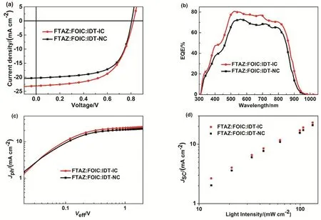
Fig. 3 (a) J-V curves and (b) EQE of optimized ternary devices; (c) Jph versus Veff curves; (d) Jsc versus light intensity.
3.3 Film morphology
We used atomic force microscope (AFM), transmission electron microscopy (TEM), grazing incidence wide-angle X-ray scattering (GIWAXS) and resonant soft X-ray scattering(R-SoXS) measurements60to characterize the binary and ternary blends morphology. The AFM images of binary blends and ternary blends show smooth and uniform surface morphology with similar mean-square roughness of 0.55-1.0 nm (Fig. S8, Supporting Information). TEM images show similar trend (Fig. S9, Supporting Information). As shown in Fig. S10 (Supporting Information), pristine FTAZ shows a favorable crystallinity, while IDT-IC and IDT-NC are more crystalline than FOIC in terms of broader scattering peaks of FOIC. As shown in Fig. 4, for the binary blends, FTAZ:FOIC exhibits sharp (100) and (200) peaks deriving from FOIC,which locates at 0.45 and 0.90 Å, respectively. Compared with pure film, the sharp peaks indicate enhancement of lamellar stacking of FOIC, and a relatively strong π-π stacking(coherence length (CL) = 2.49 nm) leads to the best JSCin three binary systems. FTAZ:IDT-IC displays an edge-on orientation without apparent π-π stacking peak, which is not beneficial to charge transport, leading to a low JSC. FTAZ:IDT-NC shows moderate crystallinity with the (010) peak located at 0.78 Å(q = 1.78 Å-1, CL = 2.15 nm). The high-crystallinity donor FTAZ blended with low-crystallinity acceptor FOIC exhibits a good performance. However, FTAZ blended with strong-crystallinity acceptor IDT-IC causes the absence of crystallinity of both donor and acceptor; the weak π-π stacking is responsible for the low JSC. As for the ternary systems,FTAZ:FOIC:IDT-IC exhibits a face-on orientation and an increased π-π stacking (CL = 2.05 nm) relative to FTAZ:IDT-IC. The FTAZ:FOIC:IDT-NC film exhibits a similar crystallinity (q = 1.78 Å-1, CL = 2.10 nm) to FTAZ:IDT-NC.Interestingly, obvious side-chain packing peak of FOIC in FTAZ:FOIC are not observed in both ternary blends, though 50% FOIC still remains. The lamellar stacking of FOIC is obviously suppressed by the third component. Furthermore,FTAZ blended with low-crystallinity FOIC and highcrystallinity IDT-IC balances the crystallization of twoacceptors and generates the best performance.

Fig. 4 (a-e) 2D GIWAXS patterns of binary and ternary blends; (f) 1D GIWAXS line-cuts of binary and ternary blends.
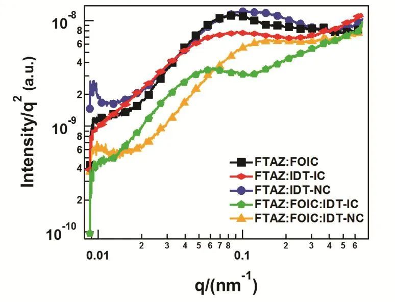
Fig. 5 R-SoXS profiles of binary and ternary blends.
R-SoXS measurements were applied to characterize the phase separation of the binary and ternary blends (Fig. 5). Here,the photon energy of 284.8 eV was adopted in order to obtain the max materials contrast. Multi-peak fitting was also used to figure out the peak location to calculate the phase separation mode length scale by ξmode= 2π/qmode, and the domain size is the half of ξmode61,62. For the binary blend, the domain sizes of FTAZ: FOIC, FTAZ:IDT-IC and FTAZ:IDT-NC are 42, 40 and 31 nm, respectively. A smaller domain size of FTAZ:IDT-NC reduces charge recombination, leading to a higher FF, while low domain purity (51%) limits the charge carrier mobility and JSC63. The ternary system FTAZ:FOIC:IDT-NC has not only a small domain size (26 nm) but also a relatively high domain purity (84%), leading to enhanced FF. As for FTAZ:FOIC:IDT-IC, the increase phase mixing (domain purity 37%) results a higher amount donor:acceptor interfacial area where excitons can effectively dissociate, although the domain size is also large (61 nm).
4 Conclusions
We designed two ternary blends, FTAZ:FOIC:IDT-IC and FTAZ:FOIC:IDT-NC, in order to investigate the effects of the two non-fullerene electron acceptors, IDT-IC and IDT-NC, as third components on ternary OSCs. When the third component weight ratio in acceptors is 50%, the FTAZ:FOIC:IDT-IC ternary devices exhibit the best PCE of 11.2%. The ternary-blend OSCs yield simultaneously improved VOC, JSCand FF compared with the binary devices based on FTAZ:FOIC. The higher VOCis attributed to higher LUMO energy level of IDT-IC compared with FOIC; the reason for improved JSCis the complementary absorption of FOIC and IDT-IC. The FTAZ:FOIC:IDT-NC system yields a lower PCE of 10.4% relative to FTAZ:FOIC: IDT-IC. Compared with the binary devices, the VOCincreases due to the higher LUMO energy level of IDN-IC, while the JSCdecreases due to the overlapped absorption of FOIC and IDT-NC.
The terminal groups in the third components affect performance of the ternary OSCs. Replacing phenyl terminal groups by naphthyl terminal groups leads to down-shift of LUMO energy level, red-shift of absorption and higher electron mobility. The lower LUMO energy level of IDT-NC is responsible for the lower VOCof FTAZ:FOIC:IDT-NC devices.The red-shift of absorption of IDT-NC leads to overlapping of absorption spectra of IDT-NC and FOIC and lower JSC. On the other hand, replacing phenyl terminal groups by naphthyl terminal groups influences the π-π packing and charge transport. FTAZ:FOIC:IDT-NC blend exhibits higher electron mobility and more balanced charge transport than FTAZ:FOIC:IDT-IC, leading to higher FF.
Acknowledgment:X-ray data were acquired at beamlines 7.3.3 and 11.0.1.2 at the Advanced Light Source, which is supported by the Director, Office of Science, Office of Basic Energy Sciences, of the U.S. Department of Energy under Contract No. DE-AC02-05CH11231. The authors thank Chenhui Zhu at beamline 7.3.3, and Cheng Wang at beamline 11.0.1.2 for assistance with data acquisition.
Supporting lnformation:available free of charge via the internet at http://www.whxb.pku.edu.cn.