
Online Magnetic Flux Leakage Detection System for Sucker Rod Defects Based on LabVIEW Programming
2019-02-28 07:09OuZhangandXueyeWei
Computers Materials&Continua 2019年2期
Ou Zhang and Xueye Wei
Abstract: Aiming at the detection of the sucker rod defects, a real-time detection system is designed using the non-destructive testing technology of magnetic flux leakage (MFL).An MFL measurement system consists of many parts, and this study focuses on the signal acquisition and processing system. First of all, this paper introduces the hardware part of the acquisition system in detail, including the selection of the Hall-effect sensor, the design of the signal conditioning circuit, and the working process of the single chip computer (SCM) control serial port. Based on LabVIEW, a graphical programming software, the software part of the acquisition system is written, including serial port parameter configuration, detection signal recognition, original signal filtering, real-time display, data storage and playback. Finally, an experimental platform for the MFL detection is set up, and the MFL measurement is carried out on the transverse and longitudinal defects of the sucker rod surface. The experimental result shows that the designed acquisition and processing system has good detection performance, simple design and high flexibility.
Keywords: Magnetic flux leakage testing, real-time detection, sucker rod, LabVIEW,acquisition and processing.
1 Introduction
In the exploration of onshore oil fields, artificial lift technology is needed to ensure the oil production of mature oil fields [Camponogara, Guardini and Assis (2018)]. Sucker rod pumping unit is well-known as the primary method to lift oil for its relative low investment and maintenance cost, simplicity, reliability and applicability to a wide range of operating conditions [Aliev, Rzayev, Guluyev et al. (2018)]. The sucker rod pumping has been a common practice in global oil production since it was put forward [Neely and Tolbert (1988)], covering over 85% of the total active well stocks in the USA, and approximately 80% of the oil wells are being produced by the sucker rod pumping in the world [Yu, Shi and Mi (2013)].
In the sucker rod pumping unit system, the sucker rod is a significant part of the power transmission in the oil well [Lao and Zhou (2016)]. It is a very slender and flexible rod,the diameter ranges from 13 mm to 29 mm in six sizes. The material constituting the sucker rod is a magnetic material and is generally composed of an alloy of steel or high-quality carbon steel. Owing to its simple construction and convenient operation, the sucker rod technique has become a significant part of the oil industry since its early stages and is still used in the vast majority of oil wells. However, the sucker rod is always subjected to the combined influences of corrosive environment and various stresses,contributing to the fracture failures during the underground working process [Benhaddad and Lee (2001)]. The failure of sucker rods has a significant impact on the oil production.There are two main reasons for the sucker rod fracture, corrosion and fatigue [Xu, Wu and Kang (2012)]. Any initial defect in the sucker rod would develop into a major problem under the conditions the sucker rod experiences. Some safety problems would arise if the tensile strength, rigidity and performance of physical chemistry of the rod become bad, resulting in tremendous losses [Yan and Peng (2009)]. Therefore, a comprehensive initial examination of the sucker rod is mandatory before and after the products being dispatched from the factory and applied in oil production. The effective inspection of the sucker rod can substantially reduce the accident probability and save the maintenance cost.
At present, there are many non-destructive testing techniques for the detection of the defects in magnetic materials. Commonly used inspection techniques include ultrasonic inspection [Turó, Chávez, García-Hernández et al. (2013)], eddy current testing [Mao and Lei (2016)] and magnetic flux leakage (MFL) testing [Ege and Coramik (2018); Suresh,Abudhahir and Daniel (2017)]. Among these techniques, which all have advantages and disadvantages, the magnetic leakage flux (MFL) method has been widely used in the detection of sucker rod defects in recent years [Zhang, Wei and Yan (2018)]. MFL inspection is a non-contact form of NDT used for examining tubular or columnar structures for the presence of defects and imperfections such as: cracks, corrosion, pits,dents, shrinkages, voids, etc. [Okolo and Meydan (2018)]. It is the most reliable, efficient and widely used approach for detecting cracks present in both the axial and circumferential directions [Wu, Liu, Wang et al. (2017)]. MFL testing does not need preprocessing and the signals are easy to acquire, so online detection can be easily carried out and a high degree of automation can be implemented.
In general, the MFL testing is a three-step process that consists of magnetization, leakage field measurements, and MFL data processing. As for MFL data processing, it includes data acquisition, storage, compression and noise reduction [Wu, Su, Wang et al. (2017);Shi, Zhang, Li et al. (2015)]. At present, there is almost no research on real-time acquisition and processing of the MFL detection of sucker rod defects. The processing of MFL data plays a crucial role in the subsequent defect identification and quantitative analysis. A good NDT signal processing system is easier to achieve for the automatic operation of detection, which helps to save time and improve the detection efficacy.
Laboratory Virtual Instrumentation Engineering Workbench (LabVIEW) plays a significant role in real-time data processing, and many scholars have used LabVIEW to process the detected data in NDT. In Reference Ege et al. [Ege and Coramik (2018)], two new pipeline inspection gauges (PIGs) which can be used to investigate the speed variable while determining defects in pipelines were designed using MFL detection technique. The voltage values of the sensors in the measurement system were saved to the computer by using LabVIEW-based software in sequential order via data acquisition card. The programs in this measurement system, which were written by using the LabVIEW programming language, were used to save the data to the computer and display them on the control panel. Ribeiro et al. [Ribeiro, Ramos and Postolache (2012)] proposed a simple algorithm used to model the eddy current inspection of an aluminum plate, which can be used to preview the acquired voltage signals. The complete system ran under the control of a LabVIEW program via a modular NI-PXI system. In Wu [Wu (2017)], a new angle sensor was presented based on the magnetoelectric effect. In the experiment of testing the proposed sensor, the output signal was monitored by an oscilloscope. In addition, a LabVIEW test system based on a data acquisition card was established.Madeti et al. [Madeti and Singh (2017)] studied the photovoltaic monitoring system,which mainly includes the sensor and its working principle, the controller used in the data acquisition system, the data transmission method, and the data storage and analysis. In this study, the collected data was transmitted to a personal computer via an RS232 serial port and was further processed by using LabVIEW data acquisition software. In Reference Li et al. [Li, Ding and Bai (2014)], a detection platform was developed to measure the three-dimensional magnetic flux based on leakage flux theory. In addition,the magnetic signals were real-time displayed, processed and stored using the LabVIEW programs. The study results demonstrated that data acquisition can be realized accurately using MFL inspection technology based on LabVIEW. Hu et al. [Hu, Zhou, Liao et al.(2015)] presented the development of a novel magnetorheological damper which has a self-induced ability. The signal acquisition card was adopted to acquire the self-induced voltage signals, the LabVIEW interface was applied to display and analyze the displacement signals.
Although many scholars have used LabVIEW to process the detected signals, no literature has given a detailed and complete LabVIEW acquisition solution. Therefore, in this paper, a complete signal acquisition and processing system is designed, the MFL data of sucker rod defects is collected, filtered, stored and replayed in real time using LabVIEW program.
The paper is organized as follows: Section 2 describes the MFL detection scheme for sucker rod defects. In Section 3, a MFL signal real-time acquisition and processing system based on LabVIEW is designed and developed. Section 4 discusses and verifies the feasibility and reliability of the designed system for the experimental MFL signals.Section 5 concludes the paper indicating major achievements.
2 MFL detection system
2.1 MFL scheme
The sucker rod is a cylindrical magnetic steel, and the MFL detection, which is a noncontact and easy to automate measurement method, is considered as an ideal nondestructive testing method. The schematic of sucker rods and typical defects are shown in Fig. 1. The transverse defect, where the defect direction is perpendicular to the rod’s axis,is shown in Fig. 1(b); the longitudinal defect is depicted in Fig. 1(c), its defect direction is parallel to the rod’s axis.
Aiming at the defects of the solid sucker rod, a detection system shown in Fig. 2 is designed and developed using the MFL non-destructive testing technology in this paper.In MFL inspection, the magnetizer used to magnetize the specimen may be a permanent magnet or an electromagnet. The electromagnetic coil is advantageous over the permanent magnet excitation, and the magnitude of magnetic flux density can be varied in the former case. For the magnetization of the specimen, the air gap between the magnetizing arrangement, specimen and geometry of the magnetizing device play a vital role [Suresh,Abudhahir and Daniel (2017)].

Figure 1: Schematic of sucker rod and typical defects
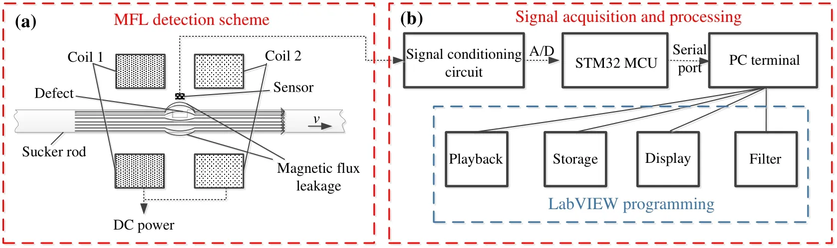
Figure 2: MFL detection system
In this design, an axial DC magnetization using magnetizing coils is used as the excitation. The sucker rod passes through the two coils which are fed by a DC power supply. When the sucker rod is magnetized to a saturated state, if there is exists a defect,then the magnetic flux will leak into the air, thereby forming a leakage magnetic field above the defect. Some magnetic sensitive sensors, such as coil sensor, Hall-effect sensor,magnetoresistive sensor, etc. can be used to pick up the MFL signals.
2.2 Hall-effect sensor
In the detection scheme, the A1302, which is a continuous-time, ratiometric and linear Hall-effect sensor, is installed for the MFL testing of sucker rod defects. The functional block diagram of A1302 is shown in Fig. 3.
It can be seen that this sensor has three pins, which are power, ground and output. The function of Cbypassis to suppress any interference on the DC supply, and allow the DC part to pass through the component with the bypass capacitor. The Hall-effect integrated circuit included in each device includes a Hall sensing element, a linear amplifier, and a CMOS Class A output structure. Integrating the Hall sensor element and the amplifier on a single chip can minimize many of the problems associated with analog signals at low voltage level. During the manufacturing process, high precision in output levels is obtained by internal gain and offset trim adjustments made at end-of-line.
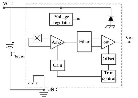
Figure 3: Functional block diagram of A1302
Supposed that the magnetic field is B, I is the current through the sensor, so the Hall voltage Vout is given by,

Obviously, the Hall voltage Vout is proportional to the field strength B and the current I.For A1302, its sensitivity is 13 V/T and quiescent voltage output is VCC/2. This Hall voltage can be measured using a signal conditioning circuit and can be used to reflect the leakage magnetic field signal. In this paper, a double Hall input is applied to collect the signals for enhancing the sensitivity and reliability of the signals.
2.3 Signal conditioning circuit
In order to transmit the magnetic leakage voltage signal collected by the dual Hall sensors to the micro controller unit (MCU), it is necessary to adjust the MFL signals, thus a signal conditioning scheme is designed, as shown in Fig. 4. Here, an adder A1 and an amplifier A2 are used to add and adjust the defect MFL signals inspected by the double Hall sensors and eliminate AC noise. The specific design circuit is depicted in Fig. 5.
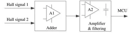
Figure 4: Block diagram of signal conditioning circuit

Figure 5: Schematic diagram of adder and amplifier circuit
For the adder, the output voltage is

We suppose that the R1=R2=R4, so, it can be noticed that this is a reverse adder. For the amplifier, the output voltage is

The output voltage range of a single Hall sensor A1302 is 0.2-4.7 V, so the output range of the double Hall sensors is 0.4-9.4 V. Due to the acquisition range of the analog to digital converter (ADC) of the MUC is 0-3.3 V, therefore, we can get constraints based on Eq. (3) as follows,
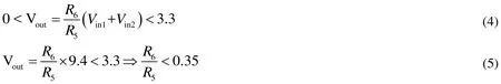
So the component values of the signal acquisition and conditioning circuit chosen in this design are listed in Tab. 1.

Table 1: Components values of the signal processing circuit
2.4 Serial communication
After signal conditioning and processing, the signal-to-noise ratio of the MFL signals is enhanced effectively. The MCU controls the ADC sampling the enhanced signals and transmits the measured signals to the computer terminal through the serial port. In this study, the RS232 serial port is performed to transmit the MFL data. Since the data transmitted by the serial port is voltage signal (the unit is V), in this design, we will retain the collected voltage signals three decimal places. RS232 is a well-known serial communication interface, which means that the MCU can only transmit voltage signals to the computer through a single character. Fig. 6 shows the process of serial transmission of a voltage signal.

Figure 6: The process of transmitting signal by serial port
A voltage signal is decomposed into 6 characters, including the integer part, decimal point, decimal part and space character. Among them, the space character is added to separate from the next voltage signal. When a voltage signal is transmitted to the computer terminal through the serial port, the integer character is sent first, then the decimal point and the decimal part are sent in turn, and the space character is sent at the end. In this way, the result of Step 6 in Fig. 6 can be obtained at the computer end, and then the next voltage signal is sent, and so on.
3 LabVIEW programming for signal processing
3.1 LabVIEW programming
After the computer receives the MFL voltage signals (i.e. a series of characters), subsequent processing is required, including acquisition, filtering, display and storage. Therefore, a real-time processing system is designed and developed based on LabVIEW programming,as shown in Fig. 7. LabVIEW can make full use of computer capabilities and has powerful data processing functions, so it is very popular among scholars. Here, the voltage signal values can be plotted, filtered or saved in order to reference them at any time while the system runs, or they can be used as inputs for further mathematical procedure.
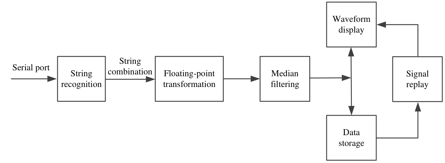
Figure 7: Block diagram of LabVIEW procedures
3.2 Signal recognition and acquisition
Fig. 8 exhibits the block diagram of the real-time signal recognition and acquisition system based on the LabVIEW program. The configuration parameters of the serial port are shown in Fig. 8(a). According to Fig. 6 in Section 2, a voltage signal contains 6 characters. When the program recognizes that there is a character transmission, that is,the data read by the serial port is not empty, the next operation is performed. As can be seen from Fig. 8(c), we added a newline character after the voltage signal to separate the next voltage signal. The combined string is converted to floating-point data and is also displayed in the receive buffer.
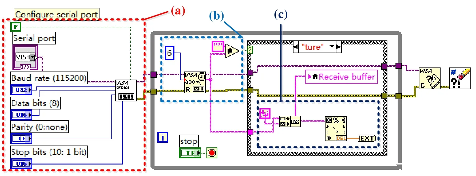
Figure 8: Program diagram for signal recognition and acquisition. (a) Serial port configuration; (b) Signal recognition; (c) String combination and transformation
3.3 Median filtering
During the detection process, due to the environmental noise and mechanical vibration,the detected MFL information contains many interference signals. Therefore, the original signals need to be filtered for subsequent defect identification. For a real-time data processing system, the filtering process of the measured original signals also needs realtime performance. Since the original MFL voltage signal is a series of discrete points, a discrete and non-linear filter, the median filter, is introduced. Median filter has a good filtering effect on impulse noise, especially when the noise is filtered out, the edge of the signals can be protected so as not to be blurred. These excellent characteristics are not available with linear filtering method. In addition, the median filtering algorithm is relatively simple and easy to implement in hardware [Niu, Zhao and Ni (2017); Shen, Ni and Chen (2016)].
When filtering a digital signal sequence, an L-long window of odd length is used, and its length L = 2M + 1, where M is a positive integer. At a certain time,the number of signal samples in the window is M, supposing that

Where f(i )is the signal sample value at the center of the window, which is defined as the output value of the median filtering.

Figure 9: Filtering process in LabVIEW
The median filter program is shown in Fig. 9. Here, the value of M is set to 4, so the difference between filtered data and original data is only 4 signals, making it possible to display two sets of data in real time.
3.4 Data storage and display
After the measured MFL data is filtered, in order to compare the effects before and after the filtering, two sets of data are simultaneously displayed in a waveform chart. The program diagram is shown in Fig. 10. Through the shift register, we store the filtered data in an array for subsequent processing or recall of the MFL information.
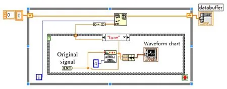
Figure 10: Data display and storage program
3.5 Signal replay
When data acquisition is accomplished, the data in the receive buffer will be stored in an array. To facilitate the re-observation of MFL data, a signal playback system needs to be programmed, as depicted in Fig. 11. It is worth noting that the signal playback system here is not real-time, it is the signal subsequent processing. In order to more clearly analyze the acquisition and display process, a playback speed control unit is also added.
Through the above detailed analysis and design of each part, a complete LabVIEW-based signal processing system can be obtained, including serial port configuration, signal identification and conversion, filtering, waveform display, data storage and playback. Fig.12 shows the front panel display of the detection system based on LabVIEW procedures.
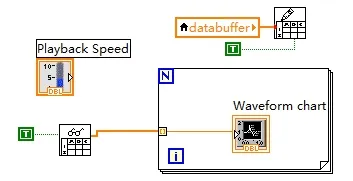
Figure 11: Signal replay program
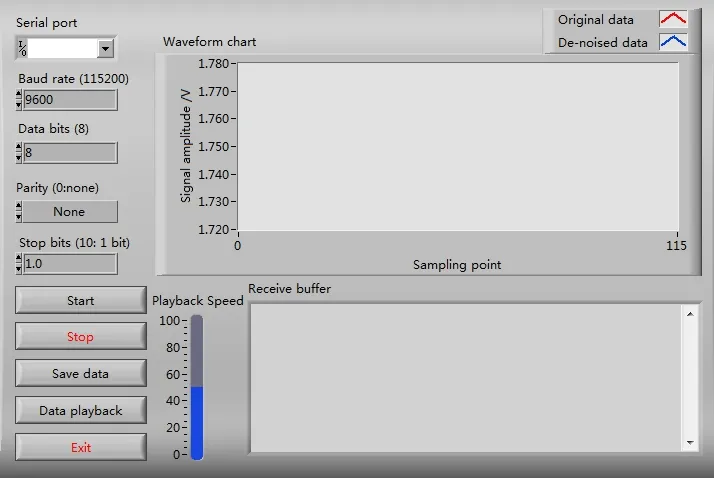
Figure 12: LabVIEW front panel display of the detection system
4 Experiments
4.1 Experimental platform
In this paper, the MFL non-destructive testing technology is used to detect the sucker rod defects online, and a MFL detection platform is set up, as shown in Fig. 13. In this experiment, a solid sucker rod with a diameter of 19.05 mm is selected as the tested workpiece. The magnetizing coils are wound in multilayer using the Litz wires and are supplied with a current of 8 A through a DC source.
In this part, experiments are carried out for different defects on the sucker rod surface, i.e.transverse defect and longitudinal defect, and the defect sizes are shown in Fig. 1(b) and Fig. 1(c). The lift-off value, which is the distance between the measured workpiece and the sensor, is set to 1 mm in the experiment.
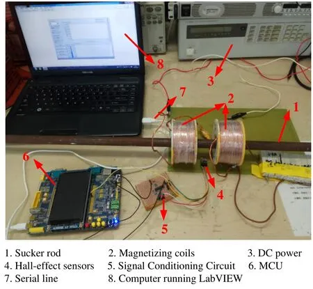
Figure 13: MFL testing platform
4.2 Experimental result
The previously designed system is used to acquire and process the detected MFL signals in real time. Before the defect is detected, the output of the two-way Hall sensor can be obtained from the Eq. (3):

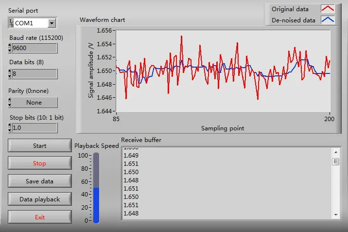
Figure 14: LabVIEW static output interface
The LabVIEW display interface at this time is shown in Fig. 14. It can be seen that the serial port of the system is selected as COM1, and the receive buffer is used to display the collected data in real time. As can be noticed from the blue curve in the waveform chart,the median filter has a good filtering effect, and the value of the MFL voltage fluctuates in the range of about 1.65 V.
4.2.1 Transverse defect
Transverse defect refers to a defect whose direction is perpendicular to the rod body, it is commonly found in the rod and the transition zone of the sucker rod. Since the axial DC magnetization method is adopted in this paper, the direction of the magnetic circuit is perpendicular to the defect direction, which is beneficial to the MFL detection. For the transverse defect artificially carved in Fig. 1(b), we obtained the results of MFL inspection as shown in Fig. 15. Fig. 15(a) and Fig. 15(b) show the normal and tangential components of the MFL signal, respectively. It can be seen that the red marked original signal fluctuates more violently, and the interference is reduced to some certain extent after filtering.
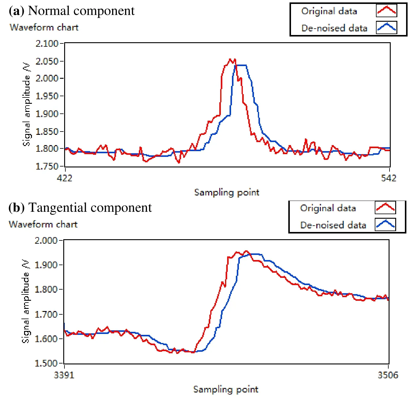
Figure 15: MFL signal of transverse defect
4.2.2 Longitudinal defect
The defect direction of the longitudinal defect is parallel to the sucker rod body, so its direction is parallel to the axial magnetization direction. It has been proved that the longitudinal defect is not conducive to the generation of the MFL signals [Zhang, Wei,Yan et al. (2018)]. In this paper, the double-coil axial magnetization method can effectively detect the MFL signals of the longitudinal defect. For the longitudinal defect shown in Fig. 1(c), the measurement result shown in Fig. 16 is obtained using the designed detection system. It can be seen that the normal component and tangential component of the MFL signals are quite obvious and can be effectively detected.However, compared with the MFL detection result of transverse defect in Fig. 15, the amplitude of the MFL signal of longitudinal defect is smaller.
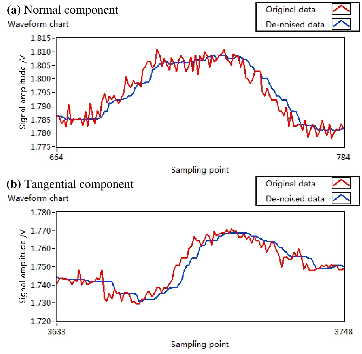
Figure 16: MFL signal of longitudinal defect
5 Conclusion
At present, as one of the most popular nondestructive testing technologies, MFL detection is widely used in various fields of industry, such as petroleum, pipelines and railways. For the on-line MFL detection of sucker rod defect, a real-time acquisition and processing system based on LabVIEW programming is designed in this paper. The study introduces the hardware and software parts of the designed system, and describes each module of the system in detail. It is obvious that the designed system is simple, powerful,and has good reliability and flexibility. Experiments are carried out on different types of defects in the sucker rod by establishing a MFL testing platform. The result illuminates that the acquisition and processing system has high detection performance and good filtering effect, and can achieve real-time acquisition, filtering, display and storage of MFL data.
Acknowledgement:This work has been supported by the National Key Research and Development Plan of Ministry of Science and Technology, Key technology research and equipment development of high speed maglev operation control system 1-5, 2016-2022(2016YFB1200602-26).
 Computers Materials&Continua2019年2期
- Computers Materials&Continua的其它文章
- Social-Aware Based Secure Relay Selection in Relay-Assisted D2D Communications
- Leveraging Logical Anchor into Topology Optimization for Indoor Wireless Fingerprinting
- An Improved Unsupervised Image Segmentation Method Based on Multi-Objective Particle Swarm Optimization Clustering Algorithm
- Forecasting Model Based on Information-Granulated GA-SVR and ARIMA for Producer Price Index
- Detecting Iris Liveness with Batch Normalized Convolutional Neural Network
- A Lightweight Three-Factor User Authentication Protocol for the Information Perception of IoT