Numerical simulation of spatial distributions of mining-induced stress and fracture fields for three coal mining layouts
Shengwei Li,Mingzhong Go,*,Xiojun Yng,Ru Zhng,Li Ren,Zhopeng Zhng,Guo Li,Zetin Zhng,Jing Xie
aState Key Laboratory of Hydraulics and Mountain River Engineering,College of Water Resource and Hydropower,Sichuan University,Chengdu,610065,China
bState Key Laboratory for Geomechanics and Deep Underground Engineering,China University of Mining and Technology,Xuzhou,221116,China
cMOE Laboratory of Deep Underground Science and Engineering,College of Architecture and Environment,Sichuan University,Chengdu,610065,China
dChina Three Gorges Projects Development Co.,Ltd.,Chengdu,610065,China
Keywords:Coal mining Mining layouts Mining-induced stress field Mining-induced fracture field Numerical simulation
A B S T R A C T In this study,the spatial distributions of stress and fracture fields for three typical underground coal mining layouts,i.e.non-pillar mining(NM),top-coal caving mining(TCM)and protective coal-seam mining(PCM),are modeled using discrete element software UDEC.The numerical results show that different mining layouts can lead to different mining-induced stress fields,resulting in diverse fracture fields.For the PCM,the mining influenced area in front of the mining faces is the largest,and the stress concentration factor in front of the mining faces is the lowest.The spatial shapes of the mining-induced fracture fields under NM,TCM and PCM differ,and they are characterized by trapezoidal,triangular and tower shapes,respectively.The fractal dimensions of mining-induced fractures of the three mining layouts decrease in the order of PCM,TCM and NM.It is also shown that the PCM can result in a better gas control effect in coal mines with high outburst potential.The numerical results are expected to provide a basis for understanding of mining-induced gas seepage fields and provide a reference for highefficiency coal mining.
1.Introduction
Underground coal mining in highly gassy coal seams can cause stress redistribution and large-scale movement of the strata,which result in the development of fracture field.The complex fracture fields increase stratum permeability and thereby provide the major channels for gas migration and drainage(Qian and Xu,1998;Xie et al.,2011).Therefore,study of stress and fracture fields is critically important to develop techniques for efficient coal mining and gas extraction.
During mining,the coal and rock in front of the mining face experience dynamic stress changes due to the decrease in confining stress,which will increase stratum deformation induced by in situ stresses in the rock subsequently(Xie et al.,2011,2016).Song et al.(1984)theoretically described the distribution of abutment pressure during coal mining in combination with field application.Singh et al.(2011a,b)studied the evolution of mining-induced stress fields during coal mining under different geological conditions and estimated the range of influenced area and the ultimate mining-induced stress over the coal pillars.Several studies(e.g.Mark et al.,2007;Guo et al.,2012;Jiang et al.,2012;Shabanimashcool and Li,2012,2013)focused on the stress evolution in a longwall mining face and presented the optimum location for gas extraction based on field monitoring and numerical simulations.He et al.(2007,2015)proposed the longwall mining“cutting cantilever beam theory”and formulated the “110 mining method”,which is considered as the third mining science innovation.Using this method,one working face,after the first mining cycle,only needs one advanced roadway excavation;while the other one is automatically formed during the last mining cycle without coal pillars left in the mining area(He et al.,2015).Compared with the conventional pillar mining method,the peak stress in roof cutting non-pillar mining(NM)method can be decreased by 11.8%-20.3%(He et al.,2018).Xie et al.(2011)simulated the mining-induced mechanical behaviors of rock for different mining layouts in the laboratory and revealed the relation between the mining layout and the mechanical behaviors of rock.However,most of these aforementioned studies focused solely on exploring the variation in mining-induced stress,but the spatial distribution and variations in the stress fields for different mining layouts are rarely reported.
It is known that the stress in front of the working face changes drastically as mining progresses.This provides the basic driving force for fracture generation and development.To understand the mining-induced fracture networks,theoretical analysis,numerical simulation,rock-like material test, field test,and other approaches are basically used.Qian and Xu(1998)studied the distribution characteristics of mining-induced fractures in the overlying strata,and revealed that the fractures are presented in the form of O-shaped circle.Yasitli and Unver(2005)numerically analyzed the deformation,displacement,stress and fracture evolution of a thick coal seam.Due to the complexity of the fracture field and its spatial distribution,fractal geometry provides an alternative to describe the fracture fields.Zhou et al.(2012)presented the self-similarity of fracture distributions in rock masses by means of model experiments on similar materials and fractal geometry.Gao et al.(2013)analyzed the spatial distribution and evolution of mining-induced borehole wall fractures using borehole video equipment.
The spatial distribution and evolution of fracture fields during coal mining have been studied extensively;however,there are few reports on how fracture fields are produced by different mining layouts.In this context,the mining-induced stress and fracture fields produced by three mining layouts are analyzed using discrete element method,in order to provide the basis for the coupling problem between the mining-induced stress-fracture-seepage fields and different mining layouts for the purpose of highefficiency coal mining.
2.Analyses of mining-induced stress and fracture fields
During coal mining,the stress field changes significantly due to rock unloading,providing the conditions for the formation of mining-induced fracture networks.The complex fracture field expands to form gas seepage pathways,which greatly changes the permeability of the coal seam.Unfortunately,the distribution and evolution of the mining-induced stress and fracture fields for different mining layouts are not well known.
2.1.Mining-induced stress fields
Various studies(e.g.Xie et al.,2011,2016)discussed the stress fields generated by different mining layouts.NM is a type of mining that removes the coal pillar in a mined-out area(goaf)or leaves small coal pillars between the underground roadway and the goaf(see Fig.1a)(Zhang et al.,2016;He et al.,2018).In Fig.1,γis the bulk density of overlying strata;H is the mining depth;K is the abutment pressure coefficient;and L1and L2are the lengths of the abutment pressure of the decreasing and increasing sections,respectively(Zhang et al.,2016).Top-coal caving mining(TCM)mainly develops a mining face along the bottom of a thick coal seam and loosens the coal at the face by abutment pressure or by blasting with the overlying coal removed after being caved(Fig.1b)(Xie et al.,1999,2016;Alehossein and Poulsen,2010;Zhang et al.,2014;Yu et al.,2015).Protective coal-seam mining(PCM)is the first step of mining performed on a seam to eliminate the risk of gas or rock outbursts during subsequent mining operations(Fig.1c)(Yuan,2008;Yang et al.,2011;Chen et al.,2014).The distribution of the stress field in front of the mining face varies for each of these mining layouts.In the NM,when the coal pillar is removed,the stress imposed by the adjacent goaf will be superimposed on the coal mass in front of the mining face.For the three mining layouts,the stress will be the greatest for the NM.In the TCM,as the goaf is relatively larger,both the scale of the mining-induced stress field and the peak stress are relatively larger.In the PCM,the protective coal-seam yields stress relief during the early stages of mining so that the peak stress is smaller.
2.2.Mining-induced fracture fields
For the three mining layouts,it is obvious that fractures can be developed in the overlying strata due to stress changes.As the mining advances,the fracture networks gradually propagate to the overlying strata and along the direction of the working face.In the NM,because the coal pillar is small or absent,the stress field changes significantly.The fracture field is widely distributed and the fractures in the coal near the mining face are frequently observed.In the TCM,due to the intensive mining activities and large mined-out volume generated,coal itself is more fractured and the extent of the fracture field is greater than that of PCM.In the PCM,where the mining width of the protective layer reaches an appropriate size,the volume of protective coal-seam will experience compression and swelling phases,and finally reach a stable stage.The fracture field of the protective layer is fully developed over the goaf,where it provides favorable conditions for gas control of the adjacent seams.
3.Numerical simulations of mining-induced stress and fracture fields
3.1.Simulation procedures
Numerical simulation is carried out using the commercial discrete element software UDEC4.0.The discrete element method allows for limited displacements and rotations of discrete elements including complete separation of elements.Prefabricated fractures are added to the model.The bottom of the model is fixed as shown in Fig.2.Then the tensile stress is applied to both sides of the model,allowing for the coalescence of cracks in the middle of the model.An inverse analysis can be carried out by adjusting the model parameters.It is possible to make the blocks equivalent to the intact module wherethe discrete fractures are added.When the boundary condition is assumed,some cracks will open,propagate and finally coalesce.
3.2.Model setup
To minimize the boundary effects on the model,the model length is defined as 300 m,the height of the overlying stratum is assumed to be 50 m,and the height of the underlying rock mass is set to be 15 m.Numerical simulations are conducted based on the geological and mining conditions of the 8212 working face in the Tashan Mine,Shanxi Province,China,where the coal seam is located at the depth of 469.4 m.To compare the three numerical models,three mining layouts(i.e.NM,TCM and PCM)are numerically analyzed at the same depth,as shown in Fig.3.It is assumed that both sides of the model have only vertical displacement and the horizontal displacement is zero.It is also hypothesized that the horizontal and vertical displacements of the underlying rock formations are both zero.The in situ gravitational stress is applied to the upper boundary with respect to the overburden depth.As for the NM model,stress of 1.3 times the original gravitational stress is applied due to the strike abutment pressure.The models for all three mining layouts simulate a mining face advance of 60 m.Simulated transverse and longitudinal fractures are set at a spacing of 1 m.
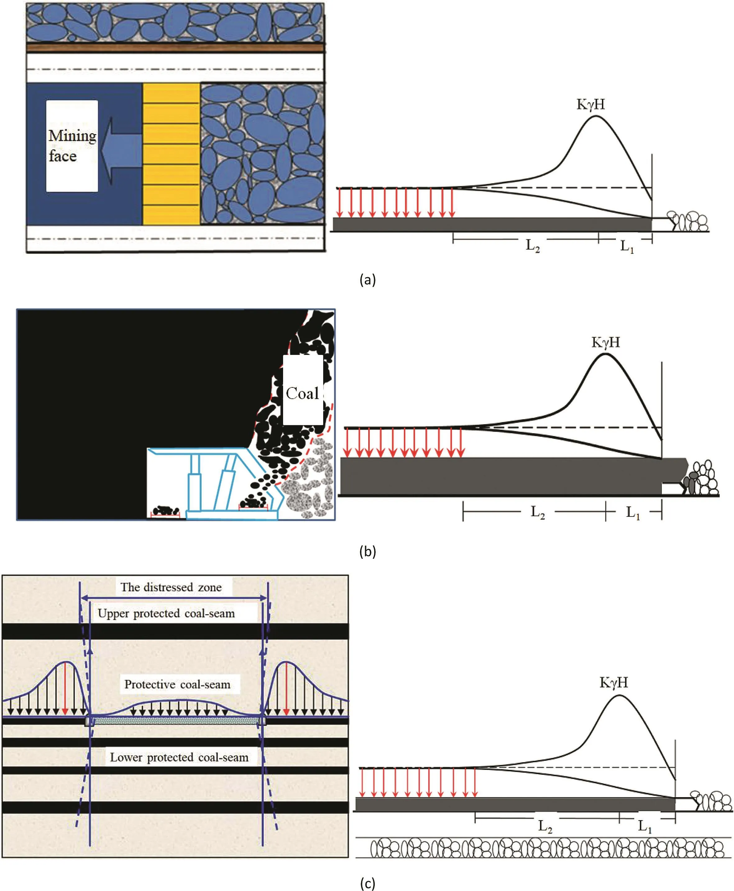
Fig.1.Spatial distribution of abutment pressures for three mining layouts:(a)Non-pillar mining,(b)Top-coal caving mining,and(c)Protective coal-seam mining.
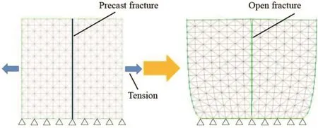
Fig.2.Schematic diagram illustrating fracture field simulation.
3.3.Parameter selection
The numerical model employs the Mohr-Coulomb failure criterion.The surface contact Coulomb slip model is adopted for the joint model.The physico-mechanical parameters of the rocks and rock joints used in the simulation are listed in Tables 1 and 2,respectively(Yu et al.,2015).
4.Results and discussion
4.1.Distribution of mining-induced stress fields
Stress field distributions for the three mining layouts are shown in Fig.4.In this figure,it is clear that there is a stressrelief zone above the goaf.Fig.5 shows the comparison of the stresses in the model.For the three mining layouts,the height of the NM stress-relief zone is the minimal and the heights of the TCM and PCM zones are similar but both with higher values.The vertical stress of the NM layout gradually increases above the stress-relief zone,but near the upper edge of the model,the stress begins to decrease,as shown in Fig.5a.At the same horizontal distance,the vertical stress for the NM layout is greater than that for TCM and PCM layouts.To obtain the advanced abutment pressure for three mining layouts,the vertical stresses at the height of 16 m in the model for NM and PCM layouts and 18 m in the model for TCM layout are calculated,as shown in Fig.5b.In this figure,the vertical stresses of three mining layouts first rise and then fall at a considerable distance away from the goaf.The peak value of the advanced abutment pressure in front of working face for NM,TCM and PCM layouts are 42.8 MPa,28.56 MPa and 28.15 MPa,respectively.The in situ stress for NM,TCM and PCM layouts are 14.58 MPa,11.53 MPa and 11.58 MPa,respectively.In terms of the peak values of the advanced abutment pressure and in situ stress,the stress concentration factors for NM,TCM and PCM layouts can be calculated as 2.93,2.48 and 2.43,respectively.Clearly,the stress concentration factors decrease in the order of NM,TCM and PCM.
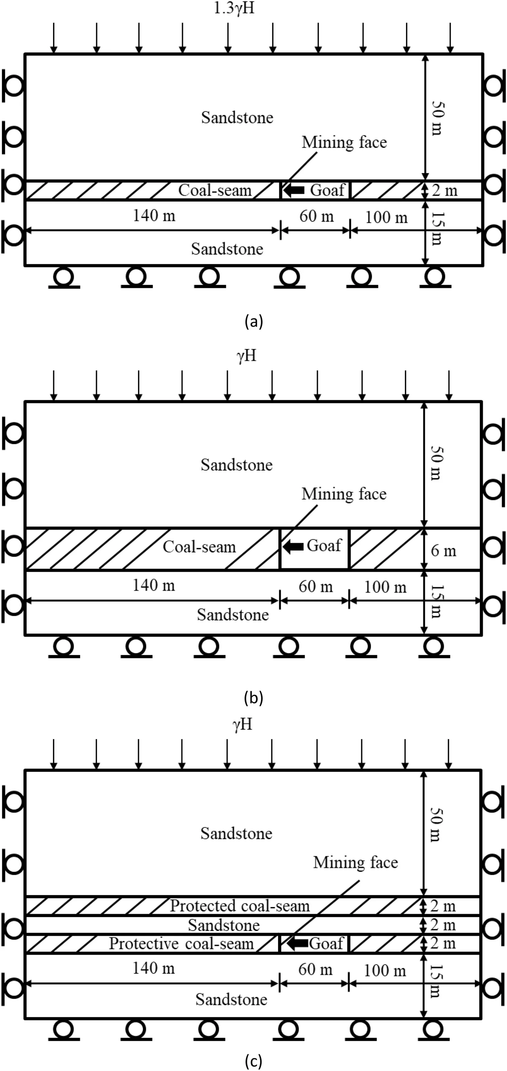
Fig.3.Schematic diagrams of numerical models for three mining layouts:(a)Nonpillar mining,(b)Top-coal caving mining,and(c)Protective coal-seam mining.

Table 1Physico-mechanical parameters of different types of rocks.

Table 2Physico-mechanical parameters of rock joints.
4.2.Shapes of fracture fields for different mining layouts
For all three mining layouts,the open fractures above the goaf are concentrated.On the basis of their orientations,the fractures can be divided into vertical and separation fractures.The vertical and separation fractures together form the open fracture field,which can be divided into following three regions.Region 1,mainly formed from separation fractures,is produced by bending deformation.Region 2 occupies both sides of the fracture field and is the most intensely fractured area.Region 3 is the caving zone,presenting trapezoidal shape distribution.There are marked differences in the regional distribution for three mining layouts.
(1)Non-pillar mining-induced fracture field
As shown in Fig.6a,the open fracture field above the goaf is trapezoidal in shape,covering the depths of 17-32 m.Region 1,at the depths of 3-18 m above the goaf,is also trapezoidal in shape with base angle of 30°.Region 2 occupies both sides of the trapezoid.Region 3 is located at the middle of goaf,showing a triangular shape.
(2)Top-coal caving mining-induced fracture field
As shown in Fig.6b,this spatial shape of open fracture field presents a triangular shape.Compared with the NM,the range of fracture field in TCM is larger,ranging from 15 m to 57 m in the model.Due to the large mining height,the falling overlying strata result in more mining-induced fractures.
(3)Protective coal-seam mining-induced fracture field
As shown in Fig.6c,the open fracture field under the PCM layout is tower-shaped,with a triangle higher than 27 m at the top of a trapezoid that is approximately 15 m high.The PCM is similar to TCM in Region 1,where fracturing in the protective layer is especially intensive.This layer has high connectivity in both horizontal and vertical directions.

Fig.4.Stress field distributions for three mining layouts:(a)Non-pillar mining,(b)Top-coal caving mining,and(c)Protective coal-seam mining.Unit in MPa.
In summary,the mining-induced fracture fields in the NM,TCM and PCM layouts are respectively trapezoidal,triangular,and tower in shape,respectively.The shapes and distributions of the fracture fields obtained in this study are basically in agreement with that obtained by means of similarity simulation,as shown in Fig.7 (Wanget al.,2009).In this circumstance,the gas drainage holes should be considered in Region 2 to maximize gas extraction.
4.3.Quantitative description of fracture fields
To describe the mining-induced fracture fields quantitatively,the fracture connectivity ratios and the field fractal dimensions are chosen as in dices to evaluate the permeability for gas transmission of the coal and rock mass.In this paper,the fracture connectivity ratio is calculated by(Chen et al.,2005):

where Niis the number of pixels that represent a single fracture projection,n is the number of fractures,and N is the number of pixels in the horizontal or vertical direction.
The box dimension method is adopted to calculate the fractal dimension of fracture fields(Falconer,1990):

where F is the bounding set of fractures for a two-dimensional plane,Nδ(F)is the minimum number of fracture sets covered by the largest diameterδ,and DBis the fractal dimension of the fracture.
As shown in Fig.8,one-dimensional(1D)connectivity ratio in the vertical direction is the highest for the PCM layout,followed by the TCM and NM layouts.The 1D connectivity ratio in the horizontal direction for the PCM is the largest,and those for the NM and TCM are almost the same(Fig.8).For the three mining layouts,the fractal dimensions are in the order of PCM>TCM>NM(Fig.8).This indicates that development of the fracture fields is in the same order,i.e.PCM>TCM>NM.
5.Conclusions
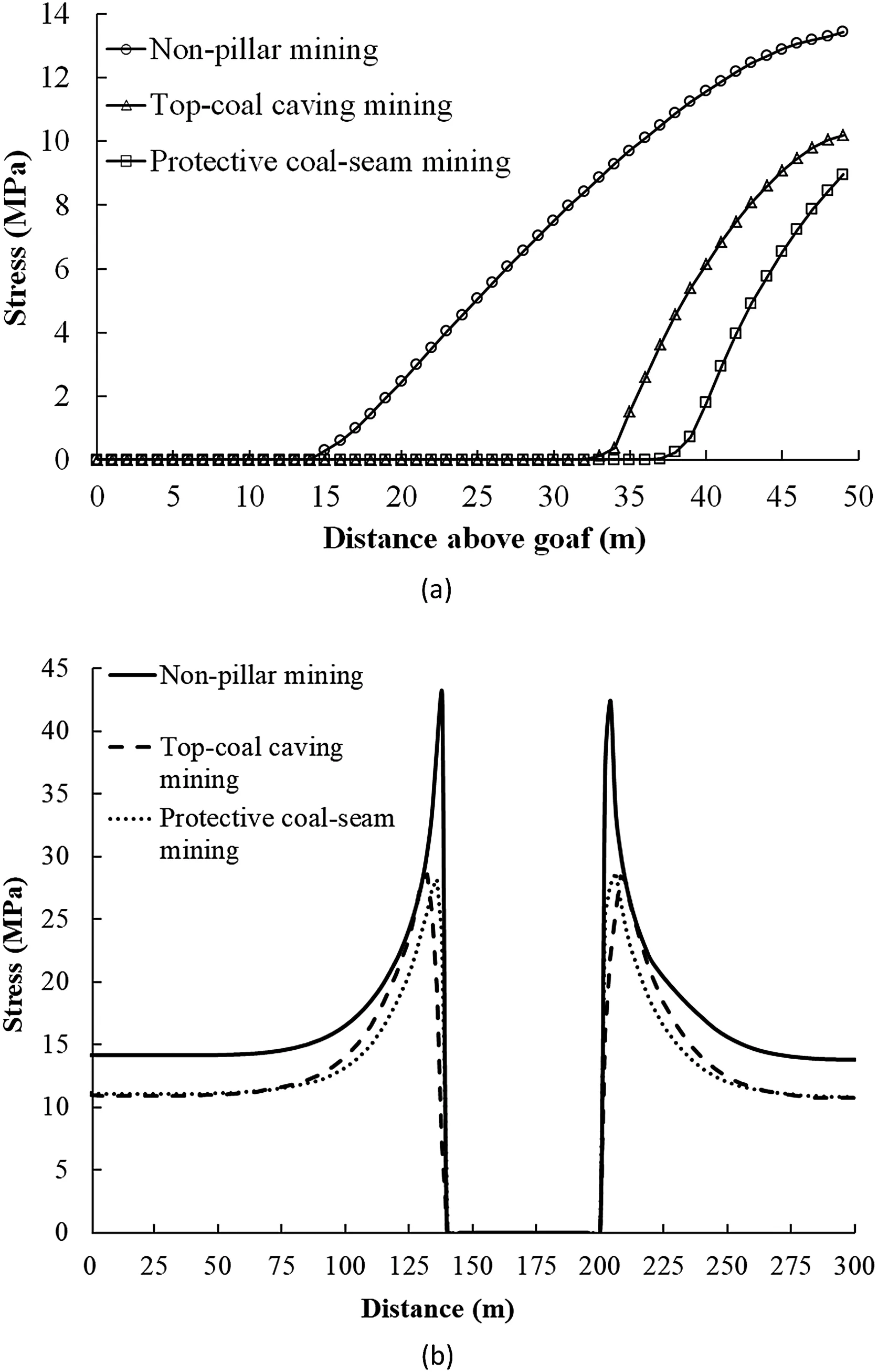
Fig.5.Comparison of stresses in the model for three mining layouts:(a)Perpendicular to the mining direction and(b)Along the mining direction.
To better understand the stress and fracture fields,numerical simulations are used to analyze the spatial distributions of the stress and fracture fields for three mining layouts.Numerical results show that different mining layouts lead to different mining-induced stress fields and associated fracture fields.The shapes of the mining-induced fracture fields produced by the NM,TCM and PCM are trapezoidal,triangular and tower in shape,respectively.The fractal dimensions of mining-induced fractures under different mining layouts decrease in the order of PCM,TCM and NM.For the PCM layout,the fracturing in the protective coal-seam is quite intensive and the permeability enhancement is remarkable.These results are expected to provide guidance for practical engineering application for the highefficiency coal mining and the simultaneous extraction of coalbed gas.
Conflicts of interest
The authors wish to confirm that there are no known conflicts of interest associated with this publication and there has been no significant financial support for this work that could have influenced its outcome.
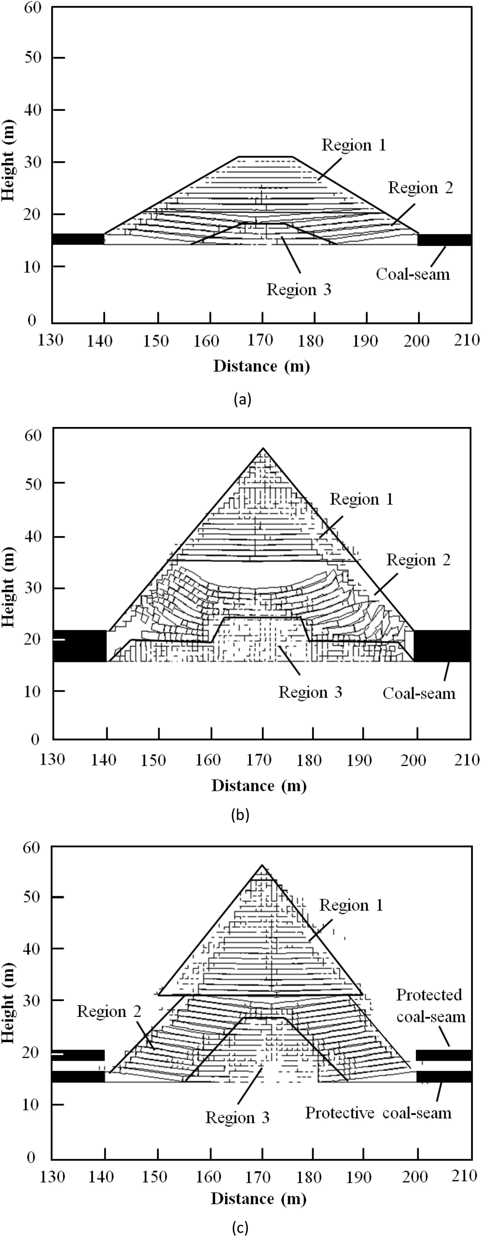
Fig.6.Fracture field distributions for three mining layouts:(a)Non-pillar mining,(b)Top-coal caving mining,and(c)Protective coal-seam mining.
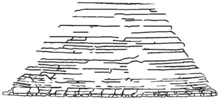
Fig.7.Fracture field distribution based on similarity simulations(Wang et al.,2009).
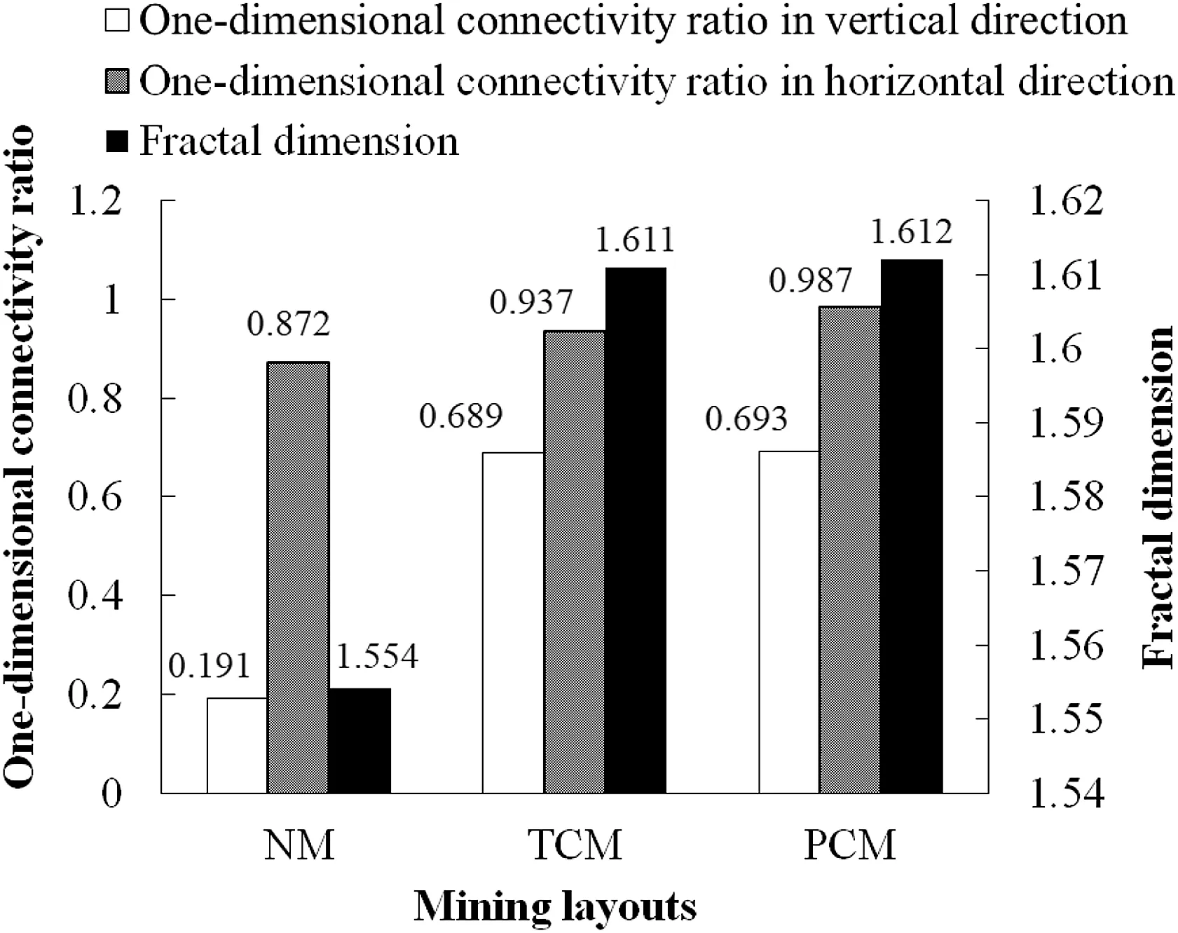
Fig.8.Histograms showing the connectivity ratios and fractal dimensions for different mining layouts.
Acknowledgements
The study was financially supported by the State Key Research Development Program of China(Grant No.2016YFC0600701)and the National Natural Science Foundation of China(Grant No.51674170).
 Journal of Rock Mechanics and Geotechnical Engineering2018年5期
- Journal of Rock Mechanics and Geotechnical Engineering的其它文章
- Pullout behavior of polymeric strip in compacted dry granular soil under cyclic tensile load conditions
- A comparative study between gravel and rubber drainage columns for mitigation of liquefaction hazards
- Bearing behavior and failure mechanism of squeezed branch piles
- Experimental evaluation of mechanically stabilized earth walls with recycled crumb rubbers
- Dynamic properties and liquefaction behaviour of cohesive soil in northeast India under staged cyclic loading
- Saturated anisotropic hydraulic conductivity of a compacted lateritic soil
