Acoustic emission characterization of microcracking in laboratory-scale hydraulic fracturing tests
Jesse Hampton,Marte Gutierrez,Luis Matzar,Danan Hu,Luke Frash
aDepartment of Civil&Environmental Engineering,Colorado School of Mines,Golden,CO 80401,USA
bNew England Research,Inc.,White River Junction,VT 03766,USA
cHalliburton,Houston,TX 77032,USA
dLos Alamos National Laboratory,Los Alamos,NM 87545,USA
Keywords:Acoustic emission(AE)Microcracking Hydraulic fracturing Laboratory-scale testing Moment tensor analysis Fracture coalescence Computed tomography(CT)imaging
A B S T R A C T Understanding microcracking near coalesced fracture generation is critically important for hydrocarbon and geothermal reservoir characterization as well as damage evaluation in civil engineering structures.Dense and sometimes random microcracking near coalesced fracture formation alters the mechanical properties of the nearby virgin material.Individual microcrack characterization is also significant in quantifying the material changes near the fracture faces(i.e.damage).Acoustic emission(AE)monitoring and analysis provide unique information regarding the microcracking process temporally,and information concerning the source characterization of individual microcracks can be extracted.In this context,laboratory hydraulic fracture tests were carried out while monitoring the AEs from several piezoelectric transducers.In-depth post-processing of the AE event data was performed for the purpose of understanding the individual source mechanisms.Several source characterization techniques including moment tensor inversion,event parametric analysis,and volumetric deformation analysis were adopted.Post-test fracture characterization through coring,slicing and micro-computed tomographic imaging was performed to determine the coalesced fracture location and structure.Distinct differences in fracture characteristics were found spatially in relation to the openhole injection interval.Individual microcrack AE analysis showed substantial energy reduction emanating spatially from the injection interval.It was quantitatively observed that the recorded AE signals provided sufficient information to generalize the damage radiating spatially away from the injection wellbore.
1.Introduction
Hydraulic fracturing in low-permeability rock is commonly used in many hydrocarbon and enhanced geothermal systems reservoirs.Throughout the fracture formation process,microcracking generally occurs in a larger region than the eventual coalesced hydraulic fracture locations.The geometry and rate of microcracking occurring during the formation of the coalesced hydraulic fracture depend greatly on the mechanical properties of the source material,the presence of discontinuities,in situ stress,loading rate,and frequency of loading(Tutuncu et al.,1998a;b).In this study,microcracking refers to the individual fractures generated at the nano-(100 nm)to micro-meter scale(100μm),while the coalesced macrofractures are in the millimeter to centimeter scale and are the result of an agglomeration of failures. This means that microcracking in the laboratory is defined by those events readily observed with acoustic emissions(AEs)in the range of hundreds of kHz,while the macrofracturing is more easily observed with strain gages or overall sample deformation measurements.AE refers to the generation of transient elastic waves in a material caused by the sudden occurrence of fractures or frictional sliding along discontinuous surfaces(Mogi,2007).Regardless of whether or not discontinuous features exist near hydraulic fractures,it is reasonable to expect that microcracking in the region adjacent to the fracture face will alter the mechanical responses of the material in that region.For instance,if microcracking near hydraulic fracture face is volumetric reduction type events(i.e.pore collapse and natural fracture closure),the permeability in that region will be reduced consequently.Thus,characterizing the microcracking surrounding the coalesced fracture face is important in understanding the state of the damaged zone of the material prior to any production operations.This information can provide a starting point for mechanical and petrophysical property changes due to pore pressure depletion operations,rather than using original virgin material properties as the starting point for production analysis of reservoir materials.
To characterize microcracking near the coalesced fracture faces,laboratory hydraulic fracturing test was carried out while monitoring AEs on eleven piezoelectric transducers. Typically, the stress release in the form of an elasticwave is a result of permanent damage caused within the source material, such as microcrack initiation. AE source location studies have shown the staged formation of damage within a rocky material until final rupture occurs(Mogi,1962,2007;Lockner and Byerlee,1977;Lockner,1993;Rudajev et al.,2000).Specifically,AE activity has been divided into several stages by several authors and the interpretation has varied depending on the type of fracturing that is occurring as well as the boundary conditions that have been applied.Mogi(2007)described the staged AE progression as three stages throughout a rock fracture test:(i)stage A,initial stage in which no appreciable AE events occur; (ii) stage B, AE events begin to occur and their sources are distributed randomly throughout the specimen;and(iii)stage C,sources of the AE events begin to concentrate in limited regions where rupture is occurring.Although,in stage C, the AE activity typically narrows to a relatively small region of microcracking,the actual rupture takes place through this region and the individual microcrack events may or may not be directly connected to the rupture face.Fig.1 illustrates this concept of microfracture generation throughout a continuous axial loading of an unconfined cylinder sample.The AE events shown in this figure in black color are not subdivided into particular stages,but act as snapshots in time of the accumulation of microcracks throughout a test.As seen in Fig.1,small microcracks occurring throughout the loading and failure stages of a material oftentimes are not directly connected to the coalesced fracture,but rather occupy a damaged zone near the final fracture face.The mechanical and petrophysical responses of the material in the localized regions will differ depending on the original properties of the rock,the induced discontinuities,and the local state of stress.
To study these individual micro-failures and the possible effects they have on the rock structure,the source mechanism of the AE microcrack must be characterized.Several source characterization methods are reported in the literature including polarity distribution of first arrival signals,frequency analysis,b-value analysis,moment tensor inversion, and many others (Aki and Richards,1980;Enoki and Kishi,1998;Ohtsu,1989;Dufumier and Rivera,1997;Vavrycuk,2001;Stein and Wysession,2003;Chang and Lee,2004;Grosse and Ohtsu,2008).Focusing on the moment tensor inversion techniques,individual microcrack characterization was performed to obtain additional information from the microcracking process near the hydraulic fracture.The individual microcrack analysis revealed the mode of failure for the majority of the observed events.Relative volumetric deformation was characterized in two manners and was shown to exhibit large energy input in the near wellbore region.Crack displacement vector information also showed significant correlations with the principal stress directions.
2.Methods
Laboratory hydraulic fracturing test has been performed in the literature using several methodologies and analysis techniques.The following describes the theoretical background,laboratory equipment,sample material,and testing procedures of AE analyses used in this study.
2.1.Acoustic emission analysis
Although AE monitoring can,in real-time,provide useful information regarding the occurrence of impending failure of a structure,additional information can also be gained regarding the microcracking process by resolving the waveform information to account for the source characteristics of the emission events.This process is called “source characterization”and is useful in understanding the moment tensor inversion techniques(Aki and Richards,1980).In laboratory,microcrack behavior when a material is subjected to loading conditions is focused on.
Moment tensor inversion AE can be used for the deconvolution of tensile,shear,and mixed mode events through the use of rock fracture tests.Full waveform analysis is tedious and often prohibitive due to the ability to observe hundreds and thousands of AE events in a single fracturing test.Ohtsu(1995)developed a moment tensor inversion method,known as simplified Green’s functions for moment tensor analysis(SiGMA),which simplifies the full-space Green’s functions of a homogeneous and isotropic material by only selecting the first arrival P-wave characteristics,such as amplitude,time,and polarity.By only using P-wave first motions for analysis,this procedure is capable of processing numerous events in a relatively short period of time.
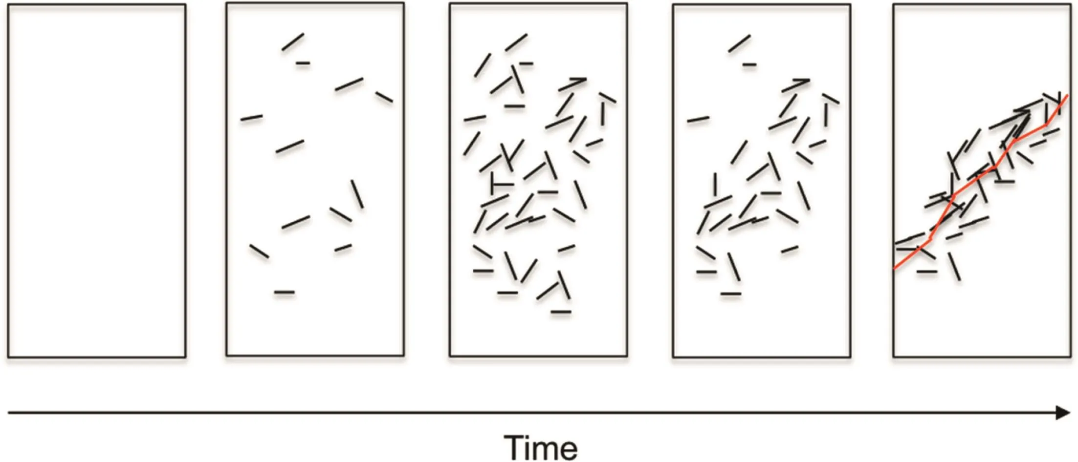
Fig.1.Progression of microcrack sources throughout a rock fracture test and eventual fracture face shown in red color.
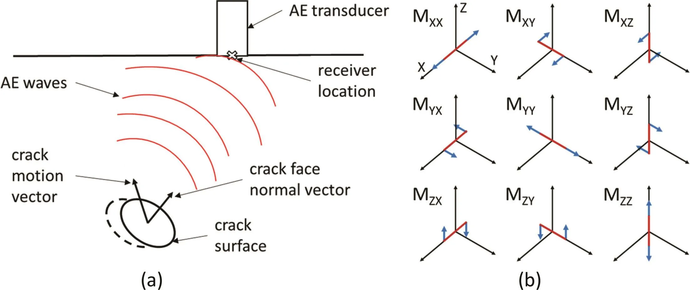
Fig.2.(a)Acoustic wave generated from crack nucleation(Ohtsu,1995),and(b)nine force couples of a moment tensor solution(Stein and Wysession,2003).
Fig.2a illustrates the fundamentals of the AE process(Ohtsu,1995).A microcrack is nucleated along the fracture surface F at point y.The vectors in the figure represent the fracture orientation and motion mathematically,where n represents the normal vector of the internal fracturing plane and b represents the displacement discontinuity or Burgers vector.As can be interpreted,the relationship between the orientation of the displacement discontinuity vector and the crack face normal vector elucidates the predominant failure mechanism of the microcrack.Displacement discontinuity vector parallel to the normal vector represents the tensile case.Conversely,the case where the displacement discontinuity vector and the normal vector are separated by 90°represents pure shear fracturing.The physical quantity of the two orientations of a crack is represented by a tensor.As Fig.2b illustrates,the equivalent tensor can be broken down into nine force couples.Eq.(1)represents these nine force couples as the moment tensor Mpq:

where mij(i,j=1,2,3)are the nine individual force couples with the subscripts representing the direction vectors.
To classify crack types from the seismic moment tensor,a unified decomposition of eigenvalues must take place.The decomposition is based on the proportions of a double-couple(DC)part,a compensated linear vectordipole(CLVD)part,and an isotropic part.Fig.3 shows the decomposition in cartoon form with orientations and magnitudes of relative forces shown.From this,AE sources can be classified into a shear crack,tensile crack,or mixed mode crack.Eigenvector information can also be obtained from the moment tensor representing the crack opening and crack slip directions.
Aki and Richards(1980)summarized a generalized relationship between seismic sources and the associated elastic waves:

where ui(x,t)is the displacement,Gip,qis the spatial derivative of Green’s function,S(t)represents the source-time function,and Mpqcan be defined as

where Cpqklis the elastic compliance tensor.
SiGMA determines six independent moment tensor components from solving a set of linear algebraic equations obtained from Eq.(2)and represented as

where A(x)is the P-wave amplitude at each of the sensor locations x;R is the distance matrix from AE source y to each of the observation sensors x;rpand rqare the direction cosine and transpose of the direction cosine of the vectors associated with source to receiver,respectively;Csis the calibration coefficient of the sensor sensitivity and is typically 1 when all sensors are similarly calibrated;and Re(t,r)is the reflection coefficient at the observation point(Ohtsu,1995).
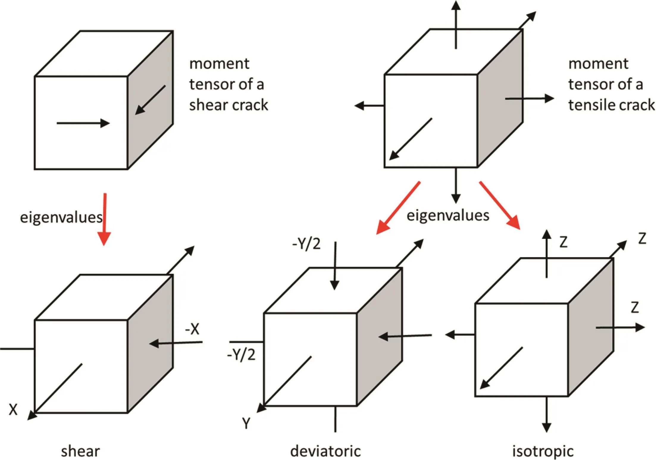
Fig.3.Decomposition of eigenvalues of a moment tensor(Ohtsu,1995).
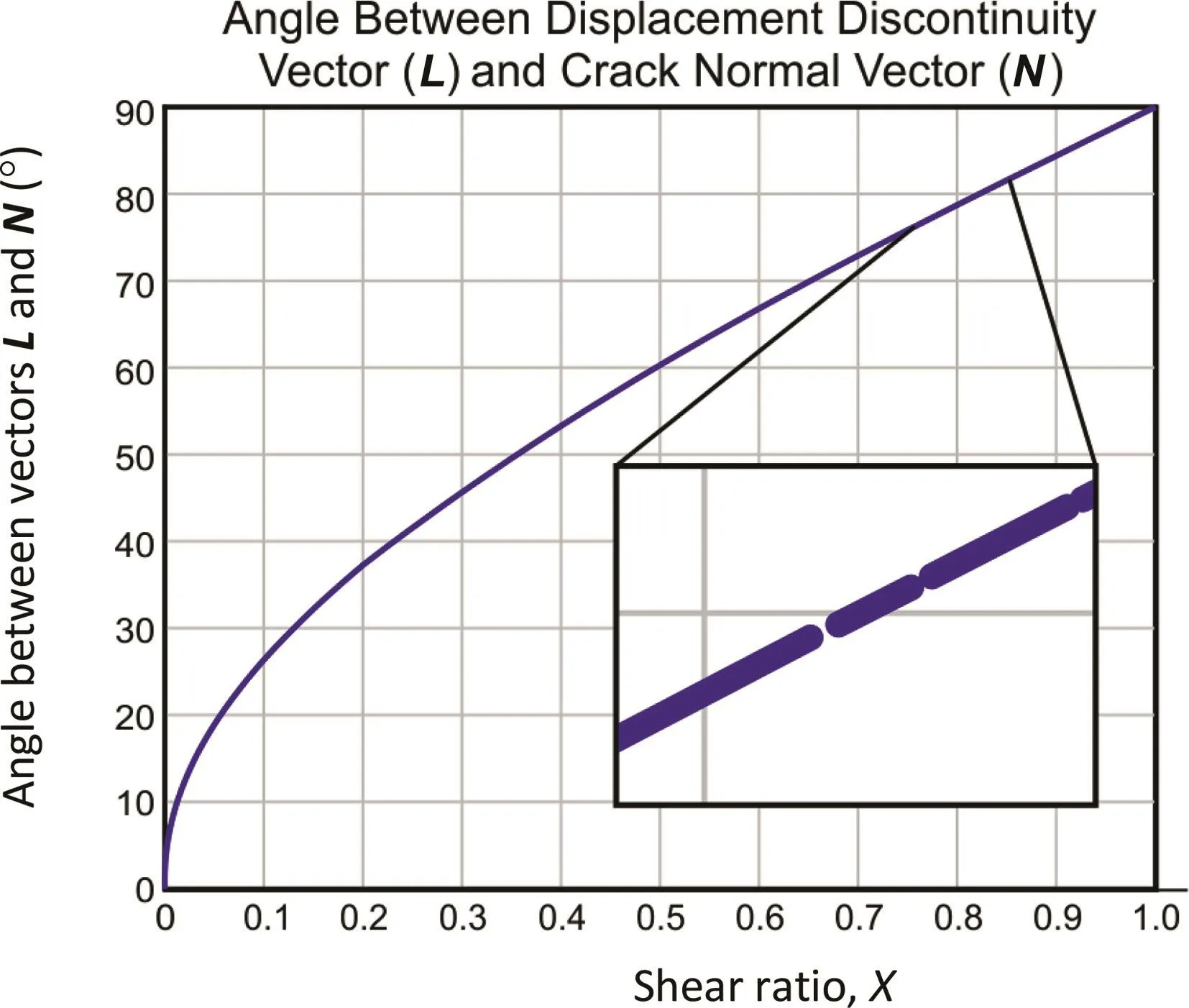
Fig.4.Experimental data showing angle between crack displacement vector and crack normal vector versus shear ratio.This figure is a scatter plot of thousands of AE event data and shows a high level of consistency(as seen in the expanded view).
Amplitude recordings at six observation points result in a linear algebraic system of equations with unknown Mpq,which is symmetric.Absolute amplitudes of an AE event are not required for the SiGMA procedure because the relative ratios of the moment tensor components are all necessary for crack type classification.Although relative magnitudes can be used to determine source mechanisms,the original magnitude of the moment tensor must be recovered in order to calculate the microcrack volume(Shigeishi and Ohtsu,2001;Hampton et al.,2014).If these values are not recovered,all relative volumes can be obtained.In an isotropic material,the moment tensor can be represented as

where l is the unit direction vector of the crack motion,μis the Lame’s second parameter,or shear modulus;and νis the Poisson’s ratio.Solving the characteristic equations of Eq.(5),the following three eigenvalues are obtained:
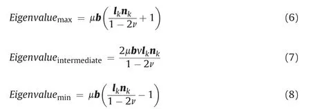
Pure shear corresponds to the case where displacement discontinuity vector l is perpendicular to normal vector n.This in turn means that ln=0.A pure tensile crack corresponds to the case where displacement discontinuity vector l is parallel to crack normal vector,meaning ln=1.Due to the observed AE signals being inherently mixed mode in nature,pure shear or pure tensile events are rarely recorded.Fig.3 shows the decomposition of the moment tensor into the DC part,the CLVD part,and the isotropic part.
Setting the maximum eigenvalue as X,the moment tensor components become X,0,and-X.Pure tensile failure moment tensor components can be decomposed into CLVD and isotropic components.Pure shear crack corresponds to the case where X=1,thus showing that X is the ratio of shear contribution.Pure tension is represented by X=0.Due to the relatively low probability that a pure shear or pure tensile failure mechanism can be observed,tensile and shear bounds of the shear ratio are used to confine the results.Shear ratios between 0.6 and 1 are used to signify shear,while ratios between 0-0.4 and 0.4-0.6 represent tensile sources and mixed mode sources,respectively(Ohtsu,1991).
2.1.1.Displacement and crack face normal vector analysis
Source mechanism characterization can be performed in multiple ways,including crack slip and crack normal vector analyses,as well as R-ratio analysis(Manthei,2005;Hampton et al.,2014).Crack slip and crack normal vector analyses consist of unified decomposition of eigenvectors of the moment tensor.Crack displacement and crack face normal directions can be determined from l+n(maximum),l×n(intermediate),and l-n(minimum).
Ohtsu(1991)showed that the angles between crack slip direction and crack normally up to 60°could still be classified as a tensile failure event.Fig.4 shows the shear ratio versus the angle between the displacement vector and crack normal vector.This image contains thousands of analyzed AE events and shows a nonlinear trend between shear ratio and angle between l and n vectors.
Although the normal vector analysis is somewhat indicative of the source mechanisms of an AE event,reliable crack type classifications are difficult to be made without addition of moment tensor inversion and a decomposition of the eigenvalues.For example,in Fig.4,an AE event with an angle between l and n of 65°still shows a shear ratio in the mixed mode region.
2.1.2.R-ratio determination
Another method for source characterization is R-ratio analysis(Manthei,2005).Using the moment tensor,ratios of volumetric versus non-volumetric components were proposed(Feignier and Young,1992).As illustrated in Fig.2b,intuitively,the sum of the diagonals of the moment tensor represents the volumetric components.Understanding that pure shear contains zero volumetric deformation,a scale of ratios R was proposed as

where m*i(i=1,2,3)are the individual force couples with subscripts associated with direction vectors.
The ratio varies from-100%to 100%for pure implosion and pure explosion sources,respectively.Pure shear mechanism is known to be 0%and pure tensile R-ratio can be calculated from the elastic properties of the rock specimen in question.

Table 1Boundary conditions and acquired data.
2.1.3.Volumetric deformation from the moment tensor
Determining actual or relative volumetric deformation provides additional insight into the fracturing process and can be performed using the observed moment tensor solutions.The trace components of the moment tensor,as shown in Fig.2b,represent volumetric deformation.The trace component can be represented as

where λ is the Lame constant and ΔV is the volumetric deformation.
Fromdamage mechanics,a damage parameter is observed in the following equation by Grosse and Ohtsu(2008):

If relative values of the amplitude observations are all known,relative crack volume can then be estimated from Eq.(11)and the following equation:

2.2.Test materials,equipment and procedure
The test material used was granite quarried and obtained from the Grant County region of South Dakota,USA.Granite was chosen because of its high strength,relative homogeneity,and low permeability.Hydraulic fracturing test was performed using a truetriaxial system and a dual pump fluid injection system.Data monitoring included flow rate,pump pressure,wellhead pressure,confining stresses,and AEs.Table 1 lists the boundary conditions and sample setup.
2.2.1.Test materials
Table 2 shows the measured rock mechanical properties.The elastic properties are reported from the average of several unconfined compression tests.The most linear regions of the stress strain curves were used to determine the elastic constants.The cohesion and friction angle were measured using uniaxial andtriaxial tests with different minimum principal stress conditions.Tensile strength was measured using the Brazilian tensile test.

Table 2Dakota granite mechanical properties.
2.2.2.Equipment
A true-triaxial system was used to simulate downhole stress ratio conditions in the laboratory.The apparatus is capable of loading a 15 cm×15 cm×25 cm(length×width×height)prismatic rock sample with independently controlled principal stresses up to 13.8 MPa.Reference axes for the aforementioned stresses are x,y,and z,respectively,for the 15 cm,15 cm,and 25 cm length directions.Stresses in the z-direction(15 cm×15 cm of application face)were applied using the biaxial load cell apparatus as shown in Fig.5.In order to apply the minimum principal stress,the entire load cell was positioned inside of a load frame.
Hydraulic injection was performed through a steel casing to a target openhole interval using a dual Teledyne ISCO 100DX syringe pump system.Injection well diameter and openhole fracturing interval diameter were approximately 10 mm and 6 mm,respectively.AE data collection hardware and software(MISTRAS Group,Inc.)were used throughout all acoustic material characterization and laboratory hydraulic fracturing test.A MISTRAS PCI-2-34 system was used,which contained 17 PCI-2 boards and a total of 34 possible signal inputs.High sensitivity and 5 mm diameter PICO piezoelectric transducers were used in order to reduce the AE sensor footprint on relatively small sample sizes.This served to increase the number of sensors used throughout testing torefine all location and source characterization efforts.A total of 11 PICO sensors were used throughout testing.Each sensor has operating frequency range of 200-750 kHz and a resonance of 250 kHz.Custom AE data analysis software was built in MATLAB in order to process the large number of AE signals in a relatively short period of time for source characterization and moment tensor solutions.
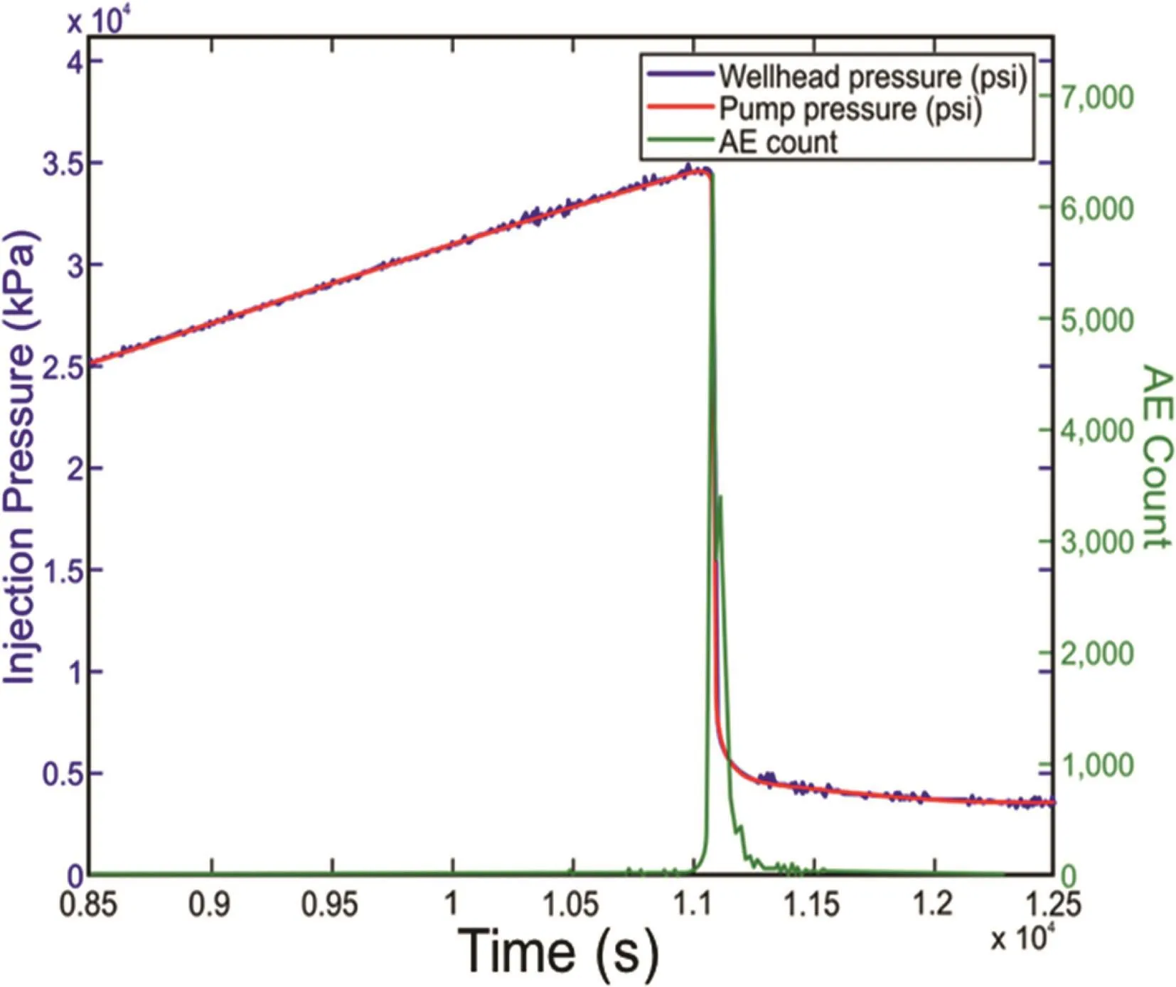
Fig.6.Observed AE histogram,pump pressure and wellhead pressure.1 psi=6.895 kPa.
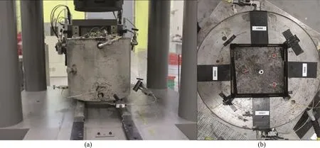
Fig.5.(a)Biaxial loading apparatus positioned inside of direct shear load frame providing the third principal stress,and(b)granite specimen inside of biaxial loading apparatus.
2.2.3.Test procedure
Prior to hydraulic fracturing test,sample characterization was performed using the AE system to understand the material wave velocity,attenuation,and proper transducer location.Active and passive AE tests were performed using auto-sensor tests(ASTs)and pencil lead break tests,respectively.ASTs sequentially create pulses emanating from each sensor on the sample.The pulsing sensor and remaining sensors all act as receivers,with a computer-controlled and initiated event initiation reference time,t0,for each signal.Highly accurate directional wave velocities can be determined.Sample characterization was performed before and after drilling and casing the wellbore.
Once all pre-test sample characterization was performed and the wellbore was drilled and cased,the sample could be placed into the biaxial load cell and pressurized to a small confinement to hold sample and sensors in place while the cell was transferred into the load frame.Wellhead pressure was monitored using a T-junction and pressure transducer.
Once trapped hydraulic system air was bled from the lines,a constant pressure injection interval was performed to check the casing seal and make the preliminary borehole permeability measurements.Upon completion of the constant pressure injection,the fracturing process was initiated.
3.Results and observations
Hydraulic stimulation was performed using gear oil.Upon completion of the constant pressure injection interval,a constant flow rate injection was initiated at a flow rate of 0.1 mL/min.Throughout the constant flow injection,AE activity was limited until injection pressure reached approximately 80%of maximum breakdown pressure.Fig.6 shows the pressure data and the approximate peak pressure of 35 MPa.The maximum(x-direction), intermediate(z-direction),and minimum(y-direction)principal stresses were13.79 MPa,6.89 MPa and 3.45 MPa,respectively.Fig.6 also illustrates a histogram of the AE events recorded throughout the hydraulic fracturing test.Low noise can be seen throughout pressure buildup until a large spike in AE activity is aligned with pressure breakdown.
3.1.AE event source location
Throughout the hydraulic fracturing test,more than 5400 three dimensional(3D)AE events were recorded on a minimum of six sensors using a multiple regression analysis of P-wave first motions.The large cloud of AE activity can be observed in Fig.7,which shows the two-dimensional(2D)orthographic projections of the 3D AE events.The orientation of the induced hydraulic fracture can be seen propagating in the xz-plane and perpendicular to the minimum horizontal stress(y-direction).The amplitude of each event is represented proportionally to the sizes of the circles.The colors of each event represent the correlation coefficient from the multiple regression analysis used in 3D source location.Red color is the highest correlation coefficient,meaning the best location(1 out of 1),and blue is the lowest(0 out of 1),with a color gradient in between.
3.2.AE event source mechanisms
Of the 5468 locatable six-sensor or greater AE events,4524 passed a filtering algorithm,which only selects those with distinguishable and high signal-to-noise ratio first arrival characteristics.Table 3 displays the results of the source characterization using the SiGMA procedure.A total of 70.5%of the observed AE events were characterized as tensile opening,while only 19.8%and 9.7%were determined to be shear and mixed mode,respectively.This is consistent with the literature where hydraulic fracturing was performed in a relatively homogeneous and intact crystalline block specimen(Hampton et al.,2013,2014).
Fig.8a displays the AE events spatially in terms of source mechanisms.A gradient of color between red and blue represents shear and tensile events,respectively.Fig.8b shows a voxelized version of the displacement discontinuity vectors and crack face normal vectors.The data were reduced by averaging location,orientation,and direction of all microcrack vector information in a 3.5 cm×3.5 cm×3.5 cm voxel.The averages are plotted in thisfigure and represent a condensed version of the vector data.This method was performed for plotting due to the large number of AE events passing the filtering algorithm;plotting each of the vectors for every event would have been meaningless because the resulting image would be indiscernible.Although performing an in-depth microcrack characterization with such a large amount of data makes the visualization and interpretation cumbersome,microcrack vector data can be visualized using a histogram plotting technique for further analysis.

Table 3AE event source mechanisms.
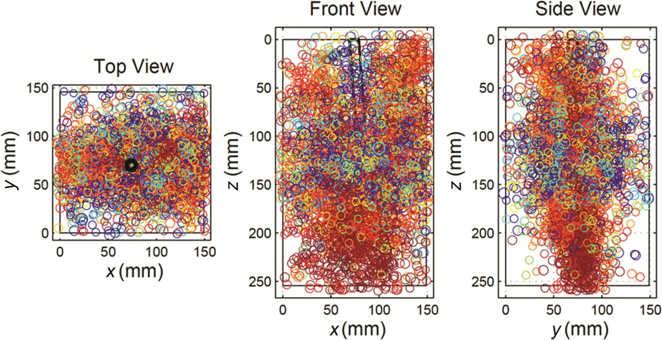
Fig.7.AE event source locations.
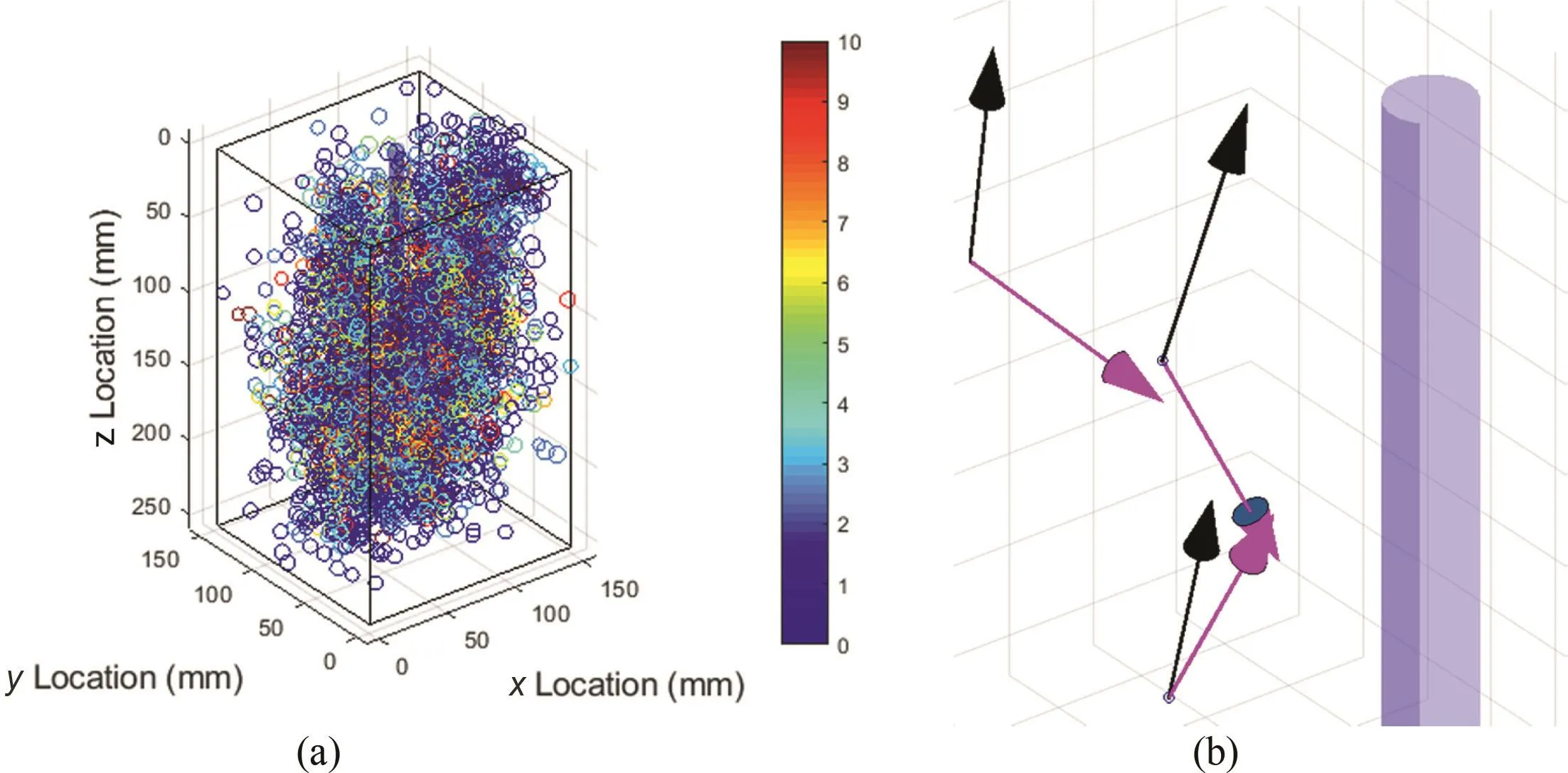
Fig.8.(a)Tensile(blue),shear(red),and mixed mode(4 through 6)source mechanisms,and(b)a zoomed in view of the voxelized AE source mechanisms showing the crack slip direction(magenta arrows)and the crack face normal direction(black arrows).
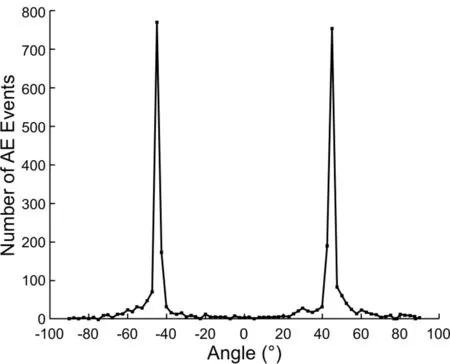
Fig.9.Histogram of angle between the microcrack displacement vectors and the zaxis.All individual events are shown here.
Although the vector information throughout the fractured sample was reduced and averaged,no discernible trends arose from these efforts.Histogram analysis was then performed to determine if relationships existed between the microcrack displacement and normal vector information,in comparison to one another and the principal stress directions.
For each individual event,the angles between crack displacement vectors and the principal stress directions were calculated and plotted.Fig.9 displays the angle between displacement vectors and the z-axis.Multiple large spikes in the number of events were observed at approximately-45°and 45°.The events were then separated by failure mode and the angle between their displacement direction and the z-axis was plotted again in Fig.10.Fig.10b shows that the tensile events almost solely contain crack displacement direction vectors with an angle of 45°from the z-axis.Fig.10a illustrates that the shear events contain displacement vectors primarily with an angle of-45°from the z-axis.
Using an alternative method for determining source mechanism,an R-ratio analysis was performed.Fig.11 shows a histogram of R-ratios.Large spikes are shown at 0,1,and approximately 0.5,representing pure shear,explosion,and tension,respectively.The number of events for shear,tensile,and mixed mode correlates very well with the moment tensor analysis solutions in Table 3.A number of explosive sources as well as implosive sources were observed during this analysis,which contributed to the total volume of AE events.
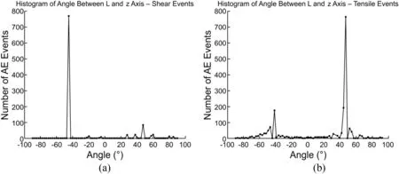
Fig.10.Deconvolution of(a)shear and(b)tensile event histograms showing orientation of the displacement vectors and the z-axis.All individual events are shown here.
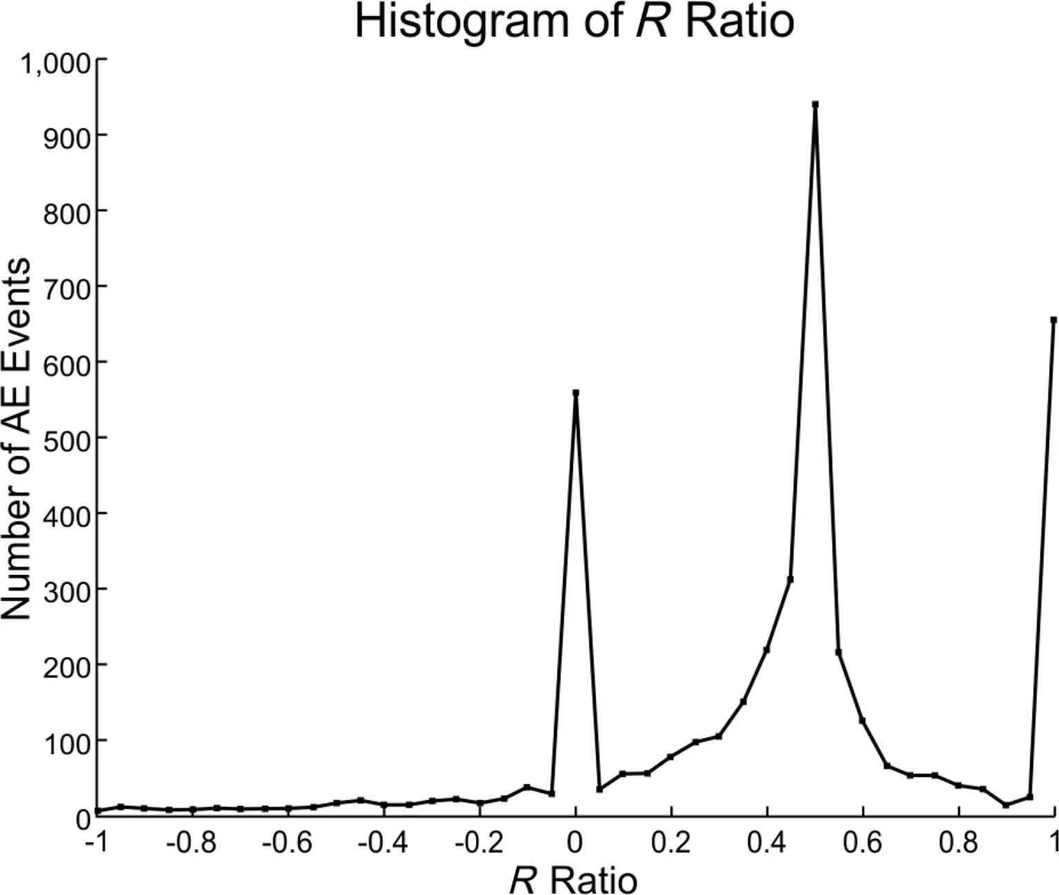
Fig.11.Histogram of R-ratios spanning between-1 and 1 for pure implosion and explosion,respectively.Zero represents pure shear,and the large spike at approximately 0.5 represents tensile opening.
The angle between displacement discontinuity vector and crack face normal vector was also calculated.Fig.12a illustrates a histogram of the results.One very large spike in the number of events was observed at approximately 38°.In Fig.12b,this corresponds to a shear ratio of approximately 0.2 and resides within the range of tensile events with a crack opening angle of 52°,which is just slightly lower than the 57°observed friction angle of the material.It was hypothesized that the angle represented an internal structure of the material and material imaging was performed with a focused ion beam scanning electron microscope(SEM).Fig.13 shows one of the many images of the rough granite face.Internal cleavage angles were identified by the orientation of the two main cleavage families.Fig.14 shows a histogram of 140 of these calculated angles.It remains uncertain why so many AE events contained failure mechanisms in this range of angles between vectors l and n.
Comparisons were made between the shear ratio and the R-ratio to investigate the unusual behavior at shear ratio of 0.2.Fig.15a shows a scatter plot of R-ratio versus shear ratio.The red circles highlight high density regions and the corresponding spikes are shown in Fig.15b.The large amount of data at 0.2 shear ratio shows almost a zero R-ratio,indicating very little to no volumetric deformation comparatively to the rest of the events with similar shear ratios.This seems unphysical for tensile dominated events according to moment tensor decomposition having a near zero volumetric deformation.Further investigation is necessary to determine whether these events are in fact just very small tensile opening events(low magnitude)or if they are unphysical observations.
To understand the sensitivity of the failure mode to this anomalous behavior,these events were removed,as shown in Fig.16.The overall failure analysis results are compared and listed in Table 4.It is shown that these events make up a significant amount of data,and the tensile,shear,and mixed mode distributions change dramatically.
AE event relative volume calculations were performed in order to understand the volume change with source mechanism and time.Relative volumes were calculated using Eq.(12).Fig.17 illustrates the calculated relative volume for each AE event with time.The majority of events are positive,with few corresponding to the negative R-ratio values as displayed in Fig.17.There were two main spikes of AE activities shown here that correspond to the pressure breakdown event.These two spikes were observed in the AE event count throughout time.
Relative volumes were separated by fracturing mechanism calculated using moment tensor analysis into tensile,shear,and mixed mode volume contributions.Fig.18 shows the event volume histogram.Table 5 lists the average relative volume for each failure mechanism.Average tensile volume is slightly higher than the average contribution from shear and mixed modes.Absolute values of each relative volume were determined to observe the total volume change within the material associated with observed AE.Larger shear average relative volume in absolute value calculations shows that many shear failure type events exhibited a negative volume change compared to those of tensile and mixed modes,which corresponds to implosive source contributions.
A cumulative volume relationship was also investigated in Fig.19.The two spikes in AE activity referenced in Fig.17 can be observed by two large increases in cumulative volume with a small interval of time in between;the small interval is located at the cumulative volume and pressure curve intersection.It is possible that these two spikes are associated with uncontrolled fracture extension to the edge of the sample,followed by a continuation of fracture extension to sample corners.One can imagine a perfectly ideal case where a penny-shaped crack is extending inside of a prismatic sample where the crack intersects the sample edges and loses some fluid pressure inside of the sample.However,the fracture continues to extend to the sample corners due to a combination of the stored strain and the lower fracture extension pressure that were required to continue the propagation.It was observed from the post-test that the hydraulic fracture was able to reach three of the four corners of the sample,which were much farther than the sample edge near the openhole wellbore.Viewing the AE behavior in time,a penny-shaped fracture appeared to develop and extend,even after AE was recorded at the nearest sample edges,suggesting that hydraulic fracture propagation continued to occur even after reaching the sample edges in some locations.
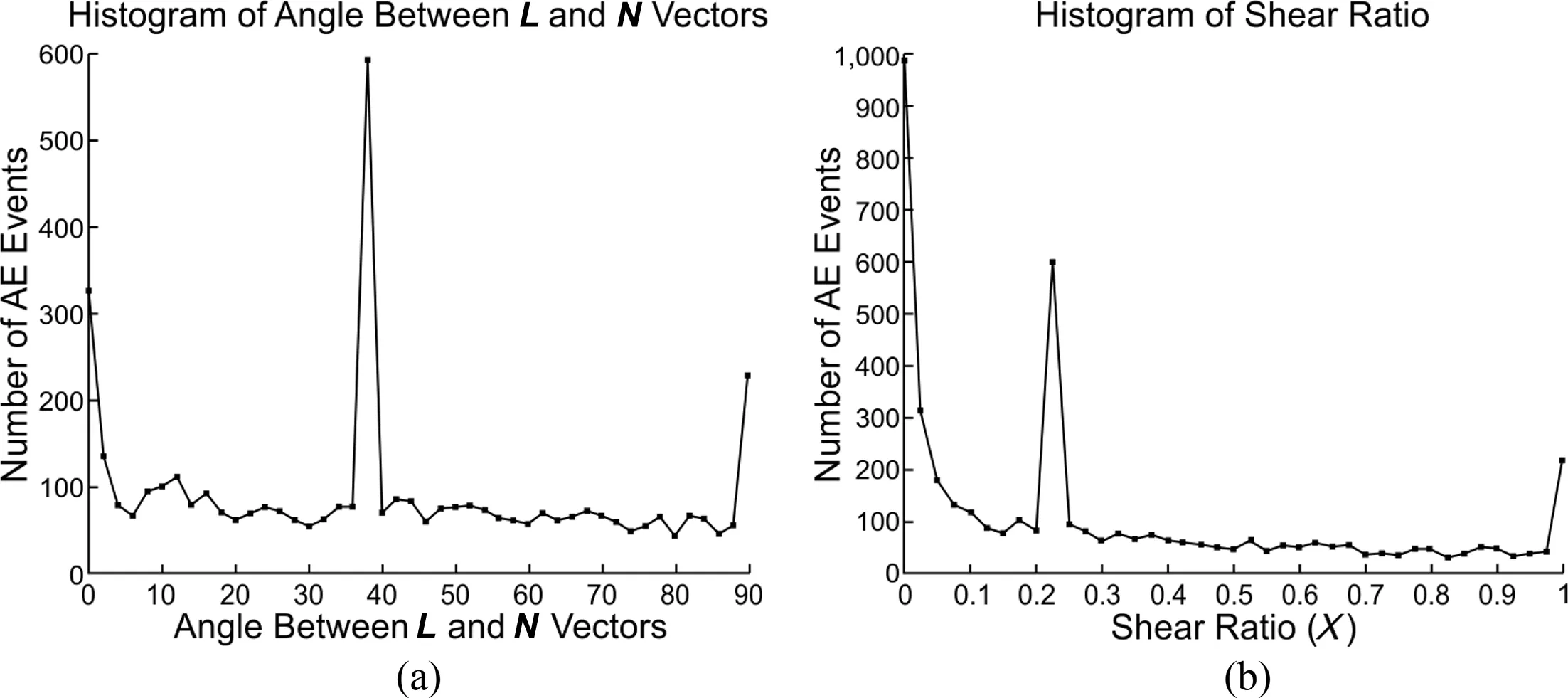
Fig.12.(a)Histogram of angle between displacement discontinuity vector and crack face normal vector showing odd behavior at approximately 38°,and(b)histogram of shear ratios observed from moment tensor solutions.
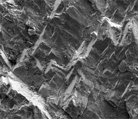
Fig.13.Single FibSEM(focused ion beam scanning electron microscopy)image of a granite cleavage structure showing preferential fracture directions.
Upon removing the sample from the confinement cell,a 50-mm core was taken,which contained the wellbore region for the purpose of computed tomography(CT)imaging and narrowing the field of study.As illustrated in Fig.20,a small section of approximately 50 mm in length and 50 mm in diameter was further investigated.Table 6 shows the relative volumetric calculations made for this cylinder of interest.It can be observed from this table that the average relative volume of tensile events in this region of interest is significantly higher than those of shear or mixed mode events.It can be speculated that the average volume of tensile opening events in this region is larger than those farther away from the wellbore because of the narrowing fracture and reduced damage zone thickness.
The ratios of tensile,shear,and mixed mode events for this reduced region were approximately equivalent to the total ratio of the entire sample.Tensile events for the cylinder of interest were approximately 70%of the total event number.Shear and mixed mode events made up approximately 22%and 8%,respectively.
3.3.CT imaging and segmentation
The wellbore and the hydraulic fractures within the granite specimen were imaged using a micro-CT scanner.CT scanning uses X-rays to create cross-sections of a 3D object that later can be used to reconstruct a virtual model without destroying the original material.The X-ray source and detector are stationary during the scanning,while the sample rotates within the micro-CT scanner.The X-ray source at a certain voltage has a limited penetration depth.The thicker the sample is,the more the X-ray signals will be dampened.It is necessary to compromise between the field of view and the resolution.In the current study,focus was given to the micro-scale hydraulic fractures induced close to the wellbore.By imaging the fracture patterns in micro-CT at a resolution of approximately 40μm,clear observations were made regarding the coalesced fractures,providing the ability to calculate the fracture volume using image segmentation processing.
The grayscale images in Fig.21 show the CT image slices.The lower the density of the material is,the darker the color shown in the CT images is.The fractures and the wellbore are composed of empty space,which has density close to zero,thus the intensity is the lowest in the open fractures and wellbore.Mainly three distinguishable materials using this resolution of scan compose the granite sample.The white dots have the highest density;the light gray has the medium density,whilst the dark gray has the lowest.The fracture in each plane is not a straight line,but is irregularly curved.The curvature of each fracture appears to follow the lower density materials and the interfaces between differing grains.The average width of the fractures is approximately 150μm.Many of the fractures are not continuous as observed by the locations at the arrow tips,where the fractures are likely to disappear.This is either due to the real discontinuities in the hydraulic fractures or due to the very thin fractures,which cannot be seen due to the insufficient resolution.The locations of the discontinuities,small enough to not be observed by this resolution,are assumed to be throughout the entire process zone,which typically spans into the surrounding material from the fracture face.
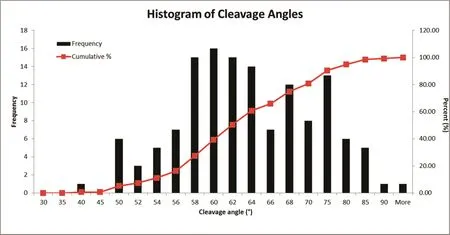
Fig.14.Image analysis of angles between cleavage families taken from several granite image sampling locations.
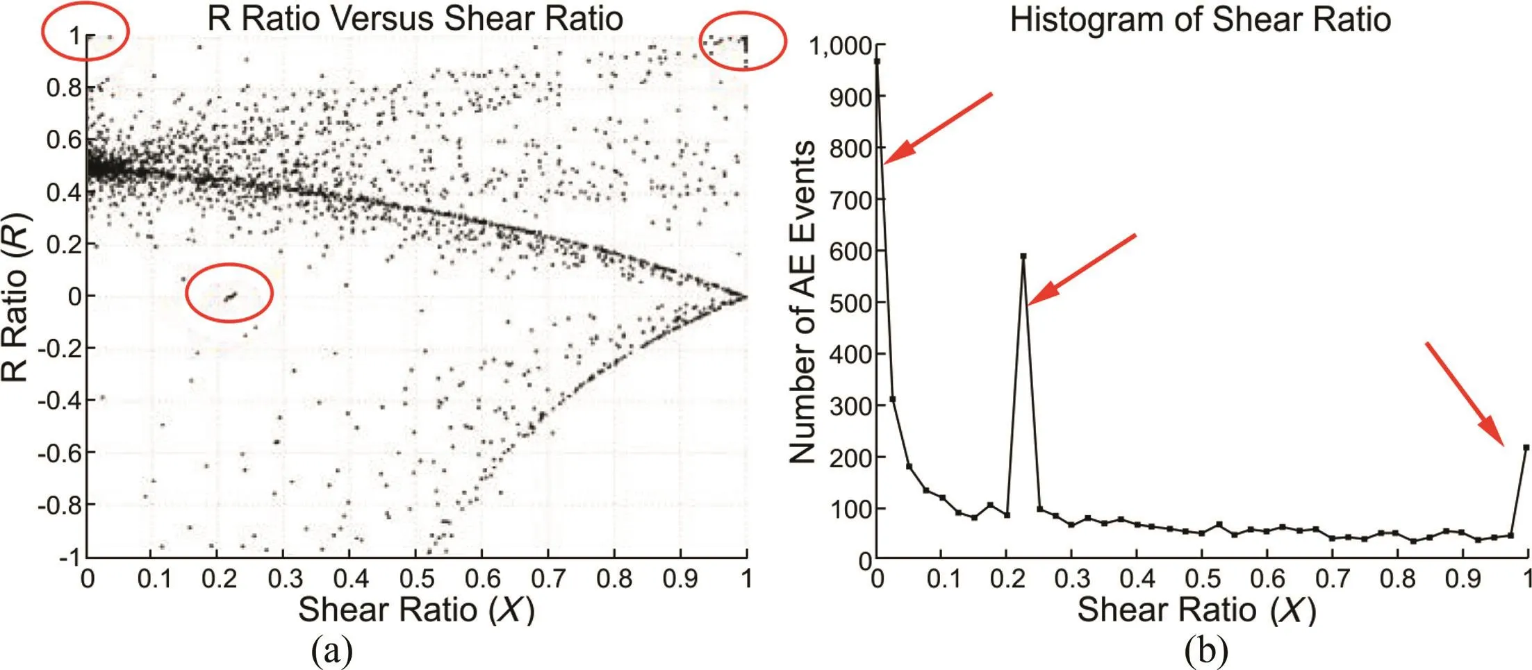
Fig.15.(a)R-ratio versus shear ratio scatter plot showing anomalous behavior,and(b)histogram of shear ratios with red arrows corresponding to high density data regions shown in(a).
In most cases,harder material corresponds to higher density.In each slice as shown in Fig.21,the discontinuity occurs at the locations with numerous white dots(highest density material inside the granite sample).There is a good match with the predictions regarding material interactions with hydraulic fractures.As depicted in Fig.21,the fracture patterns can be extracted through the image segmentation analysis(Hu et al.,2012).The blue plane denotes the fractures and wellbore.There are many open spaces on this plane,indicating the discontinuities on the fracture curves.The yellow arrow lines show the correspondence between the open holes within the fracture plane and the discontinuities in the fracture curves in each slice.The image segmentation is performed by the multi-thresholding treatment.Some fractures are well blended with their background,which has similar gray intensities,and manual operations were used to remove the over-selected areas for fractures.The number of voxels within the fracture area is measured,and the actual volume of this area is calculated by multiplying the actual volume per pixel,which is 403μm3.The calculated fracture volume in this area is approximately 250 mm3in terms of the whole field of view of 5.03×104mm3.The percentage of the fracture to the field of view is approximately 0.497%.
Fig.21 also illustrates that the fracture pattern within the granite sample is very complicated.There are many open spaces on the fracture plane,which is either attributed to the discontinuities of the fractures or to the low-resolution of imaging.
4.Discussion
Hydraulic fractures were induced in a true-triaxially confined granite block through an openhole injection interval and monitored using AE transducers.Several methods of AE event source mechanism determination were undertaken.Shear ratio produced from the moment tensor analysis was compared to crack slip and crack face normal direction vector analyses,as well as the R-ratio determination.All three methods showed consistent results,producing numerous tensile failure dominated events compared to shear and mixed mode microcracking.
Large spikes in the number of events were observed near a shear ratio of 0.2,which is classified as tensile.Comparisons were made between one of the volumetric analysis methods,R-ratio analysis,and shearratio determination to understand the anomalous behavior.It is shown that the spike observed at shear ratio of 0.2 corresponds to nearly zero volume change events,suggesting a substantial amount of very low volume change of tensile events.Hypotheses for this observed behavior range from internal cleavage family orientations to errors in the moment tensor solutions.
Volumetric calculations from the seismic moment tensor were determined and classified into tensile,shear,and mixed mode volumetric contributions.AE source mechanism and average relative volume calculation of tensile events between full sample hydraulic fracture and narrowed cylinder of interest were compared.It was observed that AE source mechanism distribution was similar,showing that 70%of events in the entire sample,as well as the cylinder of interest,exhibited tensile failure.Average relative volume calculations were performed and showed that tensile openingevents in the cylinder of interest were approximately three times greater than the total sample average of tensile events.

Table 4Moment tensor solution data with and without the anomalous data.
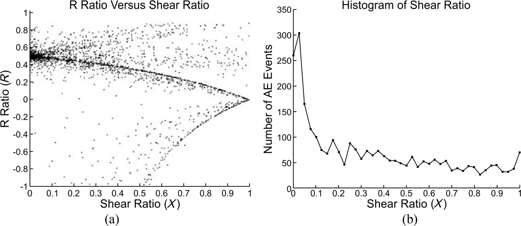
Fig.16.(a)Removal of the anomalous data,and(b)subsequently produced shear ratio plot.
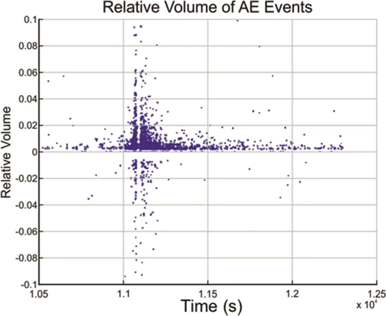
Fig.17.AE event relative volume versus time.
CT imaging and segmentation were performed to obtain an actual fracture opening volume and geometry.Although the sample was depressurized inside of the load cell,cored,and removed for CT imaging,the resultant CT images and volumetric fracture calculations from the images were assumed to have changed at an unknown amount between fracture initiation,closure,sample removal,coring and preparation.The fracturing images are meant to show the possible outcomes of the fracture widths as well as the fracture face roughness,which would not change significantly inside of the sample because of the post-test coring procedures.
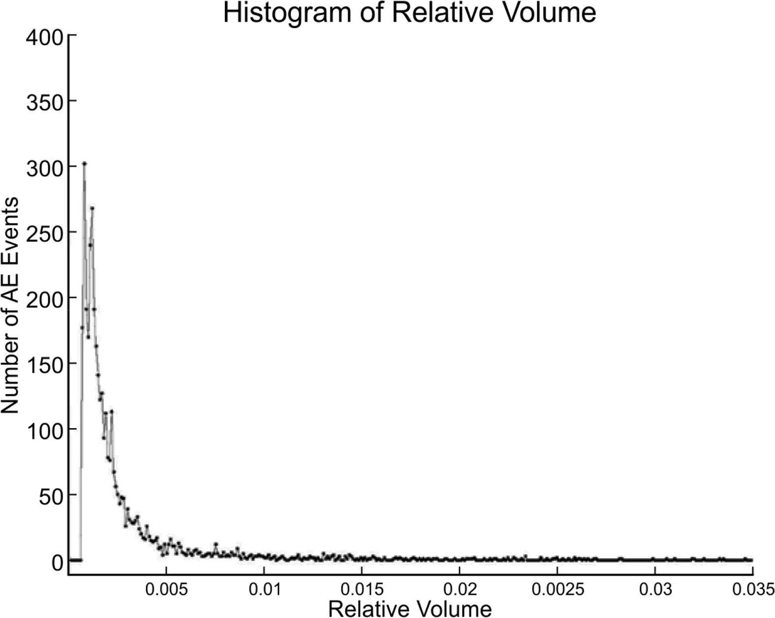
Fig.18.Histogram of relative volume observed for all AE events.
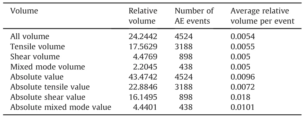
Table 5Relative volume,number of AE events,and average relative volume per event.
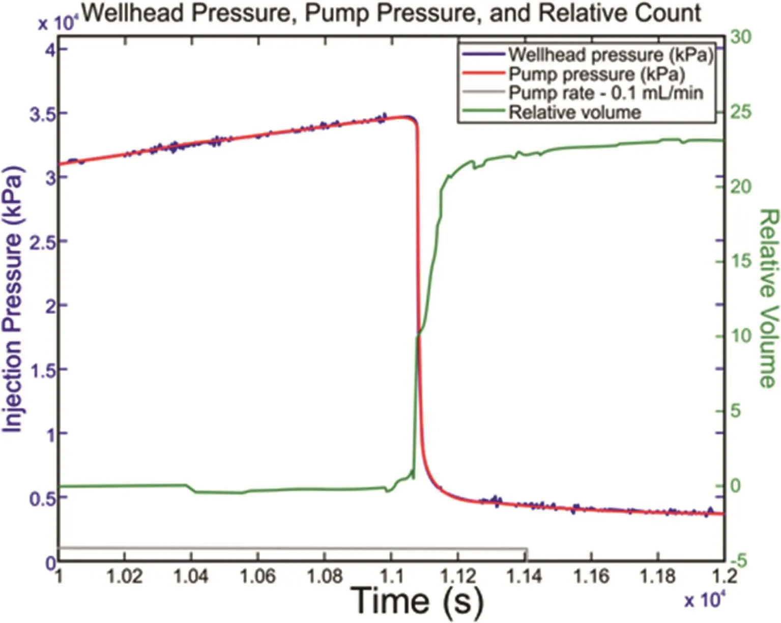
Fig.19.Cumulative volumes of all AE activities,wellhead pressures,pump pressures,and flow rates throughout time.
CT imaging showed that,even in relatively high stress contrast boundary conditions,hydraulic fractures tended to propagate throughout weaker or less dense materials and the interfaces between material types rather than making a linear trend.Although observing the sample from multiple scales shows that the fracture is approximately planar,the micro-scale behavior is displayed to be far from planar with a high level of curvature complexity and roughness.
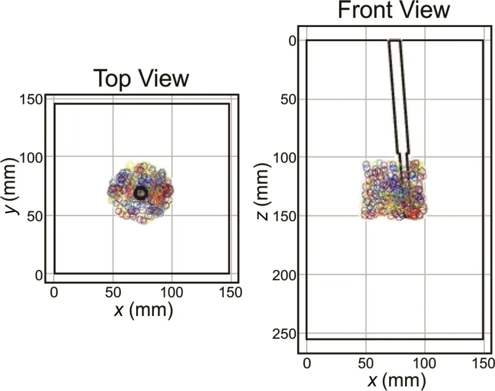
Fig.20.AE event source locations inside cylinder of interest used for CT imaging.
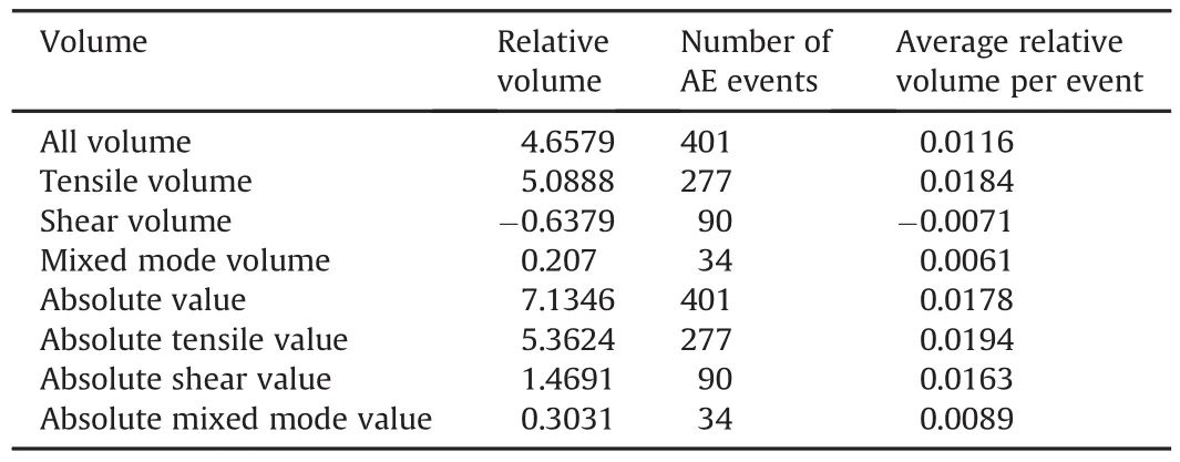
Table 6Relative volume,number of AE events,and average relative volume per event for AE events located inside cylinder of interest.
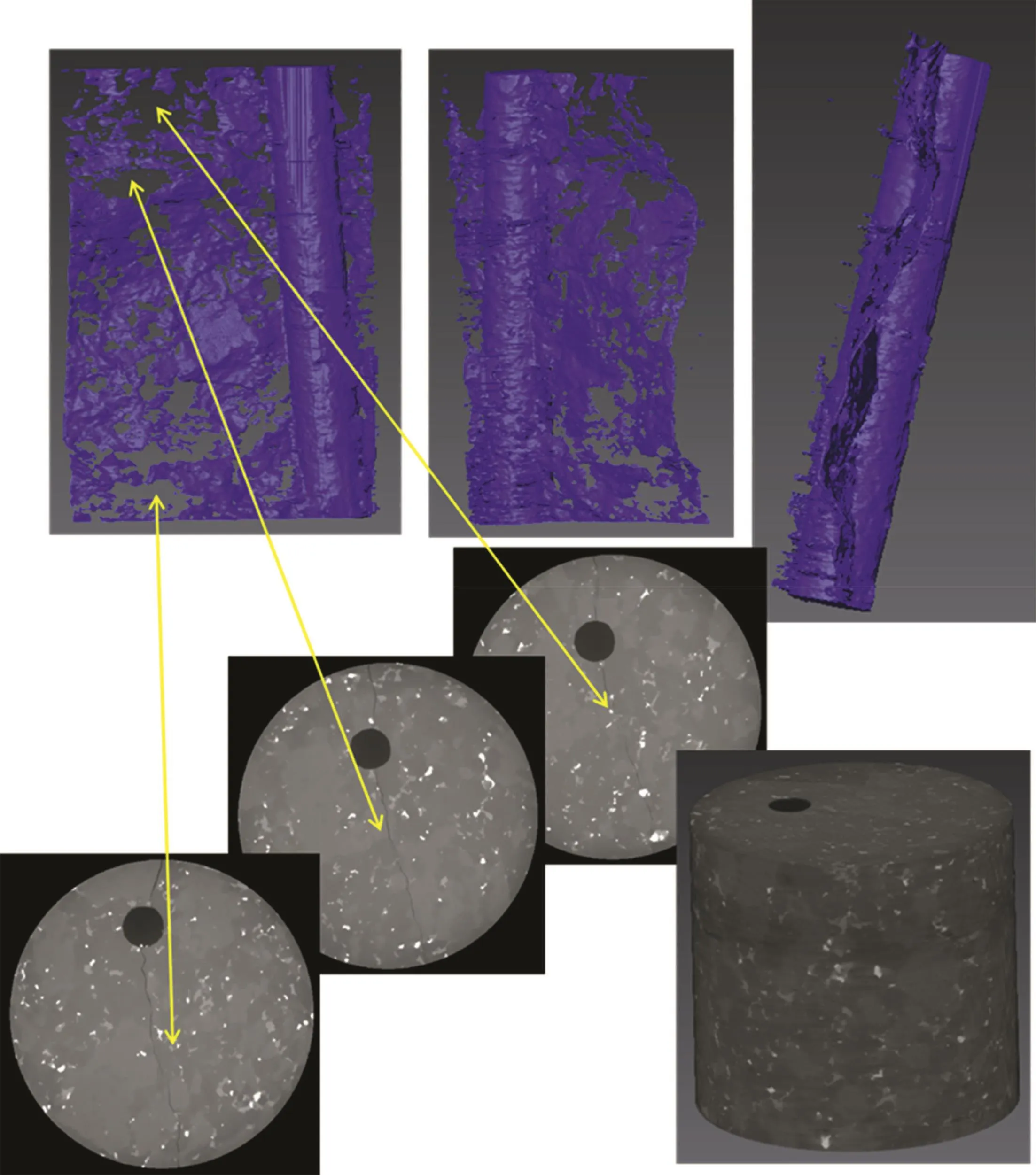
Fig.21.CT image results(grayscale images),and results of image segmentation of the fractures(blue).
Crack displacement and crack face normal vectors were determined from the AE analysis.Trends were observed in the microcrack displacement vectors with respect to the principal stress directions.Significant numbers of events were shown to have displacement vector relationships in the z-axis direction.The majority of tensile events contained an angle of approximately 45°between the microcrack displacement vector projection and the zaxis,in the xz-plane;conversely,shear events primarily contained an angle of-45°between the displacement vector projection in the xz-plane and the z-axis.Plotting the orthographic projections of the displacement vectors served to identify possible trends in the displacement information for the dense microcracking around and very near a hydraulic fracture.This type of information is hypothesized to be useful for plotting the flow characteristics in the bulk media surrounding the hydraulic fracture.For instance,if all tensile and/or shear events are oriented in a few primary directions,the semi-elliptical resultant flaws will contribute to a greater flow capacity in those directions when these flaws remain open after the microcracking process.Further study is necessary to model the reservoir flow alterations associated with a large number of semielliptical microcracks induced in multiple orientations.
5.Conclusions
Extensive AE analysis of a laboratory hydraulic fracturing experiment was presented in this context.Source characterization analysis of AE events provided a large amount of data including mode of failure,orientation and direction of crack slip and crack face normal vectors,and two methods of volumetric AE analysis.The following conclusions are drawn in this work:
(1)AE data located near coalesced fracture faces provided valuable insight into the formation of microcracks and their characteristics,including volumetric deformation,mode of failure,and orientation and direction of microcrack and motion.Adding characteristic information to source locations of microcracks,it is possible to investigate the material response to a growing fracture.Additional information gained from the source characteristics aided in interpretation of damage progression away from the wellbore.
(2)Relationships between microcrack displacement vector orientation and principal stress directions can be observed with AE source characterization.Displacement vector projections within the xz-plane had concentrated orientations at 45°and-45°with respect to the z-axis.Further deconvolution showed that tensile event displacements tended to form angle of 45°with the z-axis,while shear dominated failures formed angle of-45°.
(3)Relative volumetric deformation of AE events changed spatially throughout the sample,giving a possible indication of a damage map of energy input from the fracturing processes.Microcrack events near the wellbore and inside the cylinder of interest contained much larger volumetric deformation per event on average than microcracks occurring farther away from the openhole interval.Tracking volumetric deformation away from the wellbore would allow for a microcrack damage indicator that is not specific to microcrack density.
Further work is necessary to investigate the relationship between the individual microcrack source information and relation to the coalesced fracture attributes,including dimensions,roughness,and orientations.Additionally,individual source characterization should be investigated as possible inputs for damage mapping near fracture faces in terms of geomechanical and petrophysical property change.
Conflicts of interest
The authors wish to confirm that there are no known conflicts of interest associated with this publication and there has been no significant financial support for this work that could have influenced its outcome.
Acknowledgements
The authors gratefully acknowledge Halliburton and Colorado School of Mines for the right to publish this work.Additionally,financial support for much of the early development of the AE analysis methods was provided by the U.S.Department of Energy(DOE)(Grant No.DE-FE0002760).The opinions expressed in this paper are those of the authors and not the DOE or Halliburton.
 Journal of Rock Mechanics and Geotechnical Engineering2018年5期
- Journal of Rock Mechanics and Geotechnical Engineering的其它文章
- Pullout behavior of polymeric strip in compacted dry granular soil under cyclic tensile load conditions
- A comparative study between gravel and rubber drainage columns for mitigation of liquefaction hazards
- Bearing behavior and failure mechanism of squeezed branch piles
- Experimental evaluation of mechanically stabilized earth walls with recycled crumb rubbers
- Dynamic properties and liquefaction behaviour of cohesive soil in northeast India under staged cyclic loading
- Saturated anisotropic hydraulic conductivity of a compacted lateritic soil
