Numerical Investigation on the Features of Gasoline Mixture Flow Field with Rotary Jet Mixing
Songying Chen, Longhao Xiang and Yanpeng Qu
(Key Laboratory of High-Efficiency and Clean Mechanical Manufacture, National Demonstration Center for Experimental Mechanical Engineering Education, School of Mechanical Engineering, Shandong University, Jinan 250061, China)
Abstract: Employing the standard k-ε turbulent model and slipping grid technique, distributions of velocity and dynamic pressure and mixing time was numerically investigated to research the gasoline flow features and mixing efficiency in a gasoline mixture tank with a rotary jet mixing (RJM) system installed at the bottom center. The simulation results showed that the RJM system can achieve fully circular stir without blind corner, reaching high mixing efficiency in the mixing process of gasoline from different refining line. The mixing density difference met the mixing requirement for the first time at 31.2 s and then showed a tendency of deterioration. It met the requirement again at 58.2 s with the mixing density difference meeting the mixing criterion of 3‰.
Key words: gasoline mixing; rotary jet mixing (RJM); computational fluid dynamics (CFD) simulation; mixing time
Refinery enterprises usually adopt different processing technology to attain gasoline with different densities through various steps like atmospheric distillation, hydrogenation etc. In order to meet the national petroleum products standards, the various line components should be mixed to make the gasoline’s physical and chemical properties more uniform. Therefore, gasoline mixing is a necessary step in the production of petroleum. The mixing efficiency directly corresponds to the quality of petroleum[1].
Gasoline mixing in refinery enterprises consists of two main categories: tank mixing and pipe mixing. Tank mixing approaches include compressed air mixing[2], mechanical agitation[3-5]and nozzle mixing with pump circulation[6-8]. Compressed air mixing usually leads to the gasoline oxidation because of the air in the tank. Moreover, the compressed air will produce strong vortex which causes static electricity that immensely threatens the tank safety. Therefore, the compressed air method has a tremendous limitation in production. Mechanical agitation is also a common method in gasoline mixing, but regardless of if the axial flow or the radial flow is adopted, it still causes blind corners easily which lowers the stirring efficiency and causes high energy consumption. High-speed nozzle jet mixing with pump circulation works as follows: the gasoline enters the tank again through the nozzle jet and the submerged jet flow promotes the motion of the static fluid. Then vortexes are generated in the boundary of the jet flow, which in turn traps surrounding fluids into the jet to improve the mixing of fluids. Nozzle mixing with pump circulation is being, gradually, widely applied for its simple structure, high safety, convenient operation etc.
By 1951, Fosset[9]had already conducted the study on jet mixing and found that nozzle mixing has higher mixing efficiency than traditional mechanical agitation. In 1982, Maruyama, Ban and Mizushina[10]found that the mixing time was up to the depth of fluid and nozzle length. In 1983, Zhu and Chang[11]introduced the principle and effect of nozzle mixing with pump circulation; In 2006, Yu[2]analyzed the features of fluid filled in a tank with a rotary nozzle and the result showed that the distribution of nozzles had an obvious effect on the fluid filled. With the development of computational fluid dynamics (CFD), jet stirring gets a further promotion[12-14]. Wang[15]studied the performance of large flux nozzle based on CFD; In 2007, Wang[16]simulated the inner flow features of jet agitator numerically; In 2012, Zhang[17]et al. researched the rotary nozzle for gasoline mixing. Barekatain H[18]et al. improved the mixing by submerging the rotary jet system with CFD software in a large storage tank. Neyestanak[19]et al. introduced a new relation of estimating the mixing time of crude oil tank with a submerged rotary jet mixer. Zhong[20]et al. studied the gas-liquid two phase flow in a slurry pool with rotary jet mixing. In this paper, the rotary jet mixing (RJM), as a novel kind of stir system, is introduced into gasoline mixture to reach uniform density without blind area. The flow features and mixing efficiency is studied using computational fluid dynamics software. The paper frame is organized as follows: Geometric model and meshes that simulate the gasoline tank is introduced in Section 1, numerical investigation and results discussion is presented in Section 2, and conclusions are in Section 3.
1 Geometric Model and Meshing
1.1 Geometric model
The geometric structure of the mixing tank and RJM device is illustrated in Fig.1. Under an assumption of no pipe leak and loss of flow, the system can be assumed as closed. Thus, there are no inlet and outlet boundaries. The motivation of the whole in-tank system is provided by the source term near the outlet pipe, which approximates the function of circulating pump. For the convenience of calculation, the diameter and the height of the tank is set to be 1 m and 2 m, respectively. The rotational velocity of the RJM is 0.2 r·min-1for a gentle stirring process. The diameter of the rotary jet nozzle is 26 mm and the nozzle number is 4 in a uniform distribution across the 360° circumferential directions. One group is horizontal and another inclined upward with the axis at 30° to the horizontal level.

Fig.1 Sketch of the mixing tank and RJM device
1.2 Meshing and boundary conditions

Fig.2 Divided zones in the tank
Software Gambit 6.3 is used to mesh the model. Because the RJM system has a fixed rotating speed with constant magnitude and direction, sliding mesh is adopted to divide the whole flow zone into four parts: moving zone, static zone, source zone and pipe zone except source term. In the model, the pipe diameter is 0.03 m and the interface between zones is defined as interface and the wall of RJM system is a moving wall with a rotary speed of 0 rad/s relative to the moving zone showing in Fig.2. Static, pipe and source zones are arranged further away from the RJM device and possess large volume of the mixing tank. Tet/Hybrid 3D elements are used to mesh the three zones with TGrid method. For the moving zone surrounding the rotational fluid agitator, Hex elements are employed to mesh with Cooper. In order to assure the grid quality, the grid sizes are: 0.012 5 mm in moving zone, 0.02 mm in static zone, 0.01 mm in both source zone and pipe zone. Verifing the grid independence, the total number of grids is 732 205.
The operating pressure, with a value of standard atmospheric pressure 101 325 Pa, is set to act on the top plane of the tank withz=1 m. Gravity term with a magnitude of 9.8 m/s2and a direction pointing to minuszaxis is chosen. Since the mixing flow field is turbulent, the standardk-εmodel is applied. As for the phase, four components which can reflect the mixing state of a certain kind of gasoline, are chosen as shown in Tab.1.
The density and viscosity of the kinds of gasoline listed in Tab.1 was measured at 20 ℃.

Tab.1 Physical property and distribution zones of the main components of a certain brand mixing gasoline
1.3 Governing equations
In this study, the heat transfer and temperature variation in the flow field were neglected. The three-dimensionaln-sequation and standardk-εequations are used as the governing equations.
Continuous equation

(1)
Momentum equation
(2)
k-εequations
(3)

1.4 Calculation strategy
The continuum equation, turbulent equation and slipping velocity equation in constant flow are solved, then the volume distribution function is calculated in unsteady flow state. Therefore, the convergence can be accelerated and a convergent density field can be attained.
According to GB/T 4756—1998 manual sampling of gasoline liquid, three points,A(0.3, 0, 0.1),B(0.3, 0, 0.5),C(0.3, 0, 0.9) (units are m, m, m), are chosen as density monitoring points in the mixing tank. More serious mixing time criterion is put forward as
(4)

2 Results and Discussion
Fig.3 shows the axial velocity distribution of the RJM, in which the axial velocity in zone [-0.5, 0.5] is exactly caused by the fluid in the inlet pipe, thereby conforming to the velocity distribution law in pipe flow. The velocity profile reveals symmety from the RJM center inlet where the axial speed is maximum value. The velocity along the axial direction drops down quickly till the gasoline mixture reaches the interface between the moving and static zones, then the trend goes slightly straight forward without sharp disturbance. The area near the wall of RJM has a minus velocity value caused by the fluid turning around after crashing on the top plane of the RJM system.

Fig.3 Axial speed distribution of the horizontal nozzles in x=0 plane
From Fig.4, an obvious acceleration function of the nozzle can be seen. In the plane atx=0, two nozzles almost distribute equal flow flux, which thus produces approximately the same outlet velocity. Because of the interface of the moving zone and the static zone, the velocity aty=±0.13 decreases suddenly, then the velocity near the wall gradually declines to 0.35 m/s, thereby comforming to the velocity attenuation law. The radial velocity is nearly symmetrically distributed. One inclined nozzle group distributes flow flux and velocity according to the analogous law in they=0 plane.
The RJM system is dominated with the axial and circumferential flow, but the radial flow only appears at the surrounding of the nozzle inlet. The absolute velocity is obtained by combining the three velocities. As illustrated in Fig.5, a minimum velocity of 0.3 m/s can be kept near the wall of the tank, which meets the requirement of gasoline mixing. Across the interface, the velocity decreases about 2/3, and this is a factor that cannot be ignored in the numerical simulation. This is why the outlet speed needs to be larger than the theoretical calculation values.

Fig.4 Radial speed distribution of the horizontal nozzles

Fig.5 Absolute speed distribution of the horizontal nozzles
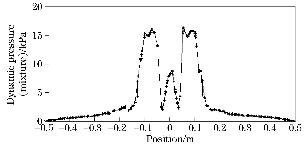
Fig.6 is quite similar to the absolute velocity distribution in their tendencies. The difference is that the effect of interface on dynamic pressure is more obvious than that on velocity. The dynamic pressure is mainly generated by the axial speed of the RJM while the dynamic pressure in other zones is a result of the jet speed of two horizontal nozzles. This justly verified the function of gathering energy and improving pressure of the nozzle.

Fig.6 Dynamic pressure distribution of the horizontal nozzles
With an increase in the radial velocity, dynamic pressure near the RJM center area affected by the transverse fluid is dropped down suddenly till the interface of static and moving zone increases. This is consistent with the result shown in Fig.4.
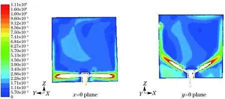
Fig.7 is the cloud chart of speed attenuation of the horizontal nozzle inx=0 plane and of the inclined nozzle iny=0 plane. The outlet speed of the nozzle is about 5.5 m/s and the speed declined to 0.5 m/s at the wall. This is slightly larger than the required value. Thus, the source term needs to be decreased. In Fig.8, the distribution of velocity inx=0 plane also showed the effect of gravity on jet speed. The gravity can make the jet trajectory incline to the bottom of the tank. The speed in the pipe declined slightly and the axial speed declined from 10.5 m/s at the outlet of the source term to 10 m/s at the inlet of the agitator.

Fig.7 Velocity distribution of the mixing phase in three planes

Fig.8 Cloud chart of velocity distribution in two planes
The whole flow field seems to be ideal, but there exists two low-speed zones with narrow regions in the opposition of the outlet pipe and around the RJM system. However, the so-called low-speed zones will disappear with the continuous velocity superposition with the rotation of the RJM system.
In the simulation process, besides theA,B,Cmonitoring points, planez=0.1 m,z=0.5 m andz=0.9 m are monitored as well. After launching the RJM system, the third phase and the fourth phase began to enter the agitator through the pipe under the action of outlet pipe and the source term. Then these two phases jet into the first phase zone through the nozzle. Before these two phases entered the pipe, they mixed in a certain region in virtue of the speed change. Therefore, among the three planes, the density change first appeared inz=0.9 m plane and mixing started in the other two planes at 4.4 s. From the point of phase, the third and fourth phase mixed in a certain region before entering in the pipe. But in the initial time, the main mixing still happened between the main phase and the third phase with the maximum volume fraction. Finally, the density of the mixing phase approached the equilibrium density 764.5 kg/m3.
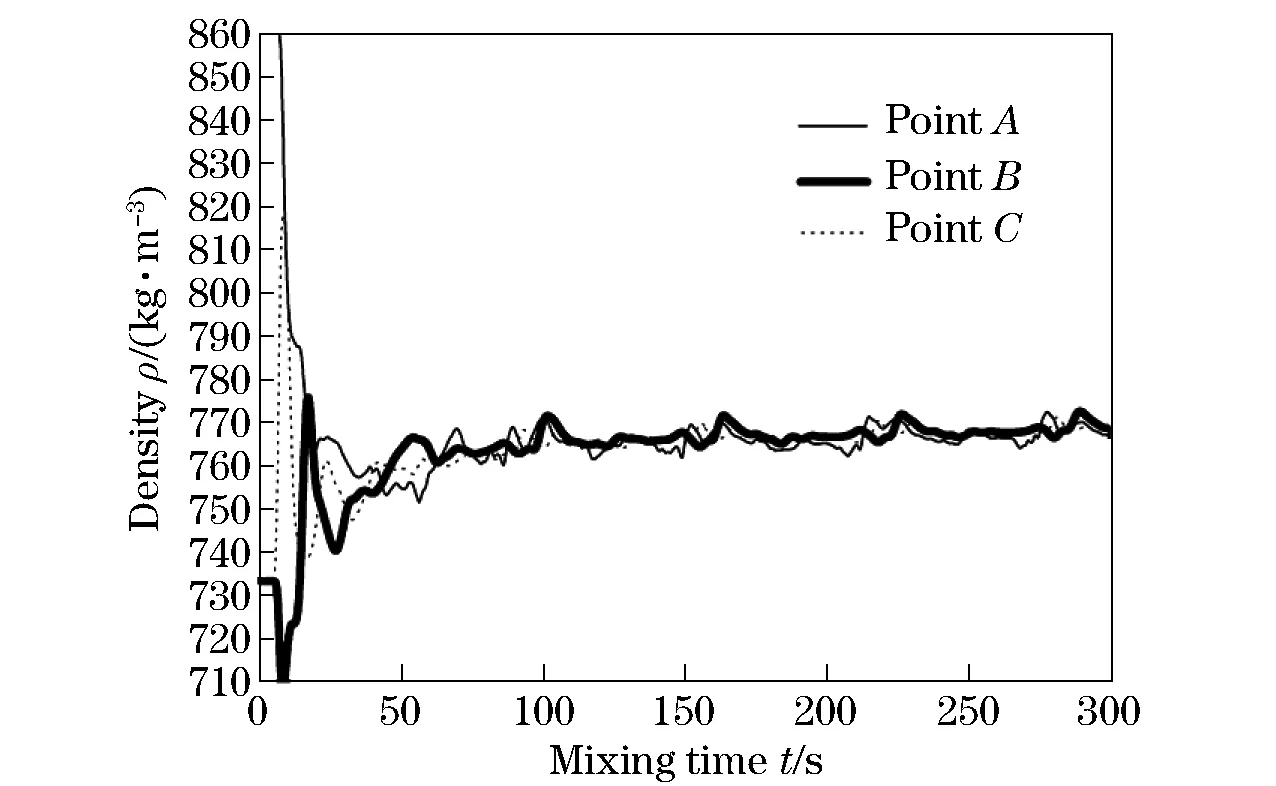
In Fig.9, the time of meeting the mixing criterion Eq.(1) for the first time is at 72.4 s and this is when the density ofA,B,Cis 764.210 57 kg/m3, 763.544 25 kg/m3and 762.067 08 kg/m3respectively. The density difference of the three is 2.81‰ and soon exceeded the limit within 1%, which is mainly caused by the sensitivity of points to value in 3D space. Hence, the mean density distribution in the three planes needs to be checked.

Fig.9 Density-mixing time curves of the three points
In Fig.10, the density values in the three planes are obtained by taking the average density of all points inz=0.1 m,z=0.5 m andz=0.9 m planes, which would eliminate the sensitivity of points to the result errors and could actually reflect the mixing effect of the flow field better.

Fig.10 Density-mixing time curves of the three planes
The mean density atz=0.1 m plane is 761.655 2 kg/m3at 31.2 s, atz=0.5 m is 763.934 1 kg/m3and atz=0.9 m is 762.173 kg/m3. The density difference is 2.992‰. This is the time which met the mixing criterion for the first time. But after 38.8 s, it went up and exceeded 3‰. The difference decreased to 2.923‰ (shown as Tab.2) again at 58.2 s and then kept within 3‰. Therefore, the mixing time of the model could be recognized to be 58.2 s.

Tab.2 Mean density in three planes at 58.2 s
3 Conclusions
This paper analyzed the flow field features of the RJM system agitating in a tank with two 30° inclined nozzles and two horizontal nozzles by numerical simulation and three conclusions were obtained:
①A minimum speed of about 0.3 m/s nearby the wall of the tank can meet the gasoline mixing requirements.
②The whole flow field seems to be ideal, but there exists two low-speed zones with narrow regions in the opposition of the outlet pipe and around the RJM system. However, the so-called low-speed zones disappear with the continuous velocity superposition with the rotation of the RJM system. There is no blind corner in the agitation.
③By analyzing the monitoring planes, it can be concluded that the mixing time of the RJM system is 58.2 s and the mixing efficiency is higher than traditional methods.
 Journal of Beijing Institute of Technology2018年3期
- Journal of Beijing Institute of Technology的其它文章
- Simplified Method for Joint Calibration of 3D Ladar and Monocular Camera
- Force Control of Electro-Hydraulic Servo System Based on Load Velocity Compensation
- Name Relevance and Contact Opportunity-Based Routing Strategy for Mobile Content Sharing
- Identification of Driving Intention Based on EEG Signals
- High-Speed Noise-Based Random Bit Generator by Removing 1/f Noise with Differential Comparison
- Radiometric Calibration Chain Design Based on Uniform Collimated Laser Source
