Systematic Synthesis on Pathological Models of CCCII and Modified CCCII
Yong-An Li, Yan-Hua Xi, Zhan-Ting Fan, Yu-Ye Zhang, and Ji-Xia Wu
Abstract—According to the equivalent view for the terminal current-voltage constraint relationship between pathological elements and the various second-generation current-controlled convegors (CCCIIs), four pathological models for the CCCII are first derived by means of the nodal admittance matrix expansion in this paper.Moreover, 48 new pathological models for the modified CCCII are also synthesized. The derived pathological models for the various CCCIIs are expected to be useful in circuit analysis and synthesis.
1. Introduction
There are two types of pathological elements. One is a nullor, the other is a mirror. Because of existence of the nullor,namely the nullator and norator, the analysis and synthesis for active circuits have become easier[1],[2]. Since a voltage mirror and a current mirror, called the mirrors, were discovered in 1999, the circuit analysis and synthesis have been expanded to the circuits with new active elements, such as the secondgeneration current conveyor (CCII)[3]-[11], current feedback operational amplifiers (CFOA)[12], operational trans-conductance amplifiers (OTA)[13],[14], current differencing transconductance amplifier (CDTA), current-controlled current convey trans-conductance amplifier (CCCCTA)[15]-[29]. These facts clearly show that pathological models of an active component are the basis of circuit analysis and synthesis. It is well known that like the OTA, the second-generation currentcontrolled conveyor (CCCII) is also a basic current-mode device and has a current-controlled output; but unlike the OTA,the CCCII has not only a voltage input but also a current input.Consequently, the CCCII is a better active device than the OTA. Recently, [30] and [31] employed pathological models of the CCCCTA to synthesize floating gyrators and Wien oscillators using CCCCTAs. They not only showed the importance of pathological models of the CCCCTAs, but also gave pathological models of the CCCII. However, the related method is not of systematic synthesis. Therefore, in modern day analog circuits, it is necessary that applying the nodal admittance matrix (NAM) expansion method synthesizes all pathological models of the various CCCIIs so that a circuit designer who understands the models well has more freedom in circuit analysis and synthesis.
2. Basic Concept of CCCII
There are four types of the CCCII, namely the CCCII+,CCCII–, ICCCII+, and ICCCII–. Fig. 1 shows the symbols of various CCCIIs and (1) presents the terminal relations of CCCIIs[30].
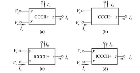
Fig. 1. Symbol of CCCII: (a) CCCII+, (b) CCCII–, (c) ICCCII+,and (d) ICCCII–.

In (1), the “+” notation in the second formula indicates CCCII and the “–” notation indicates ICCCII; the “+”notation in the third formula designates CCCII+ and ICCCII+, and the “–” notation designates CCCII– and ICCCII–. For a CCCII implemented with bipolar technology, the parasitic admittance at the x input terminal,Yx, could be expressed as

whereIBis DC bias currents of the CCCII andVTis the thermal voltage.
3. Pathological Models of CCCII
3.1 CCCII+
For the CCCII, from (1), we can find

In (3), the “–” notation in the second formula indicates CCCII and the “+” notation indicates ICCCII; the “±”notation in the third formula is the same as that in (1).
The three-port admittance matrix of the CCCII+ is then

Considering the CCCII+ with four nodes, we first insert one blank row and one blank column in (4) in the process of expanding the matrix. A nullator is then linked between columns 1 and 4 to move two –Yxfrom the first column to the fourth column. A current mirror is connected between rows 3 and 4 to moveYxand –Yxfrom the third row to the fourth row with inverted signs so that a floatingYxcan be realized between nodes 2 and 4. The expanded matrix, including the added nullator and current mirror elements represented by bracket notation, is given by (5).
The equivalent pathological model for the CCCII+described by (5) is shown in Fig. 2 (a). One important point to note is that because the stamp of the expanded matrix is sole,so is the pathological model for the CCCII+.
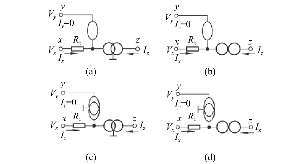
Fig. 2. Pathological model for various CCCII: (a) CCCII+, (b)CCCII–, (c) ICCCII+, and (d) ICCCII–.
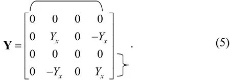
Noted that in the expanding processes, a bracket in the horizontal direction denotes a nullator, an angle bracket in the vertical direction denotes a current mirror.
3.2 CCCII–
For the CCCII–, from (3), we can find its three-port admittance matrix is

The synthesis approach of the CCCII– is essentially the same as for the CCCII+. We start from (6) and add one blank row and one blank column in (6). After two expansion steps, the expanded matrix, including a nullator and a norator represented by bracket notation, is presented by (7):
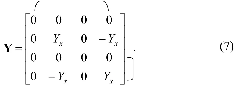
Here, a bracket in the vertical direction denotes a norator.The equivalent model for the CCCII– described by (7) is shown in Fig. 2 (b).
3.3 ICCCII+
For the ICCCII+, the three-port admittance matrix is,from (3),

As with the synthesis approach of CCCII+, we start from(8) and add one blank row and one blank column to (8). After two expansion steps, the expanded matrix, including a voltage mirror and a current mirror represented by bracket notation, is presented by (9):
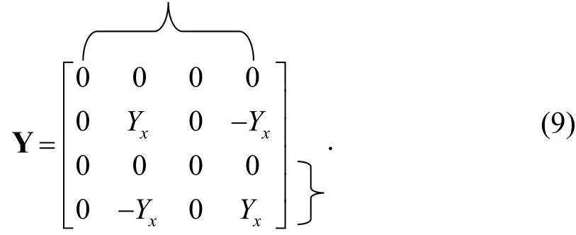
Here, an angle bracket in the horizontal direction denotes a voltage mirror. The equivalent model for the ICCCII+described by (9) is shown in Fig. 2 (c).
3.4 ICCCII–
For the ICCCII–, from (3), we obtain its three-port admittance matrix:

As before, we start from (10) and add one blank row and one blank column to (10). After two expansion steps, the expanded matrix, including a voltage mirror and a norator represented by bracket notation, is presented by (11):
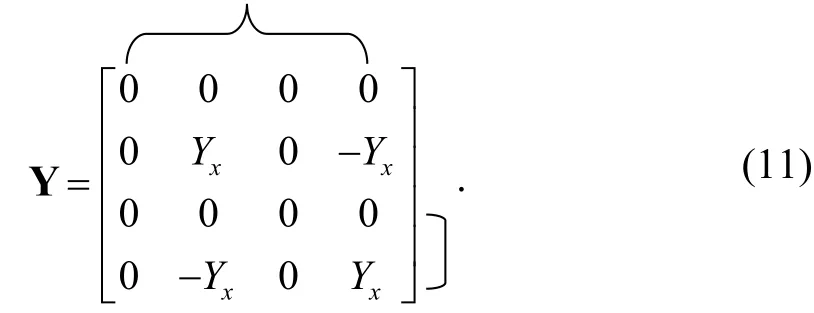
The equivalent model for the ICCCII– described by (11)is shown in Fig. 2 (d).
4. Pathological Models of Modified CCCII
The modified CCCII mainly includes the BOCCCII,BOICCCII, DOCCCII+, DOCCCII–, DOICCCII+, and DOICCCII–. Their circuit symbols are indicated in Fig. 3 and their port current-voltage relationships are as follows:

where the “±” notation in the second formula is the same as (3).
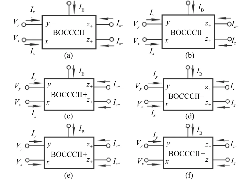
Fig. 3. Modified CCCII: (a) BOCCCII, (b) BOICCCII, (c)DOCCCII+, (d) DOCCCII–, (e) DOICCCII+, and (f) DOICCCII–.
For the BOCCCII, from (12), we can write its four-port admittance matrix as (13):

Taking into account the BOCCCII with seven nodes, we first insert three blank rows and columns in (13) in the process of expanding the matrix. Then we connect a first nullator between columns 1 and 5 to move two –Yxfrom the column 1 to the column 5, and connect a first current mirror between rows 3 and 5 to moveYxand –Yxfrom the third row to the fifth row with inverted signs so that a floatingYxcan be realized between nodes 2 and 5. It is followed that we connect a second nullator between columns 2 and 7 to move–Yxfrom the second column to the seventh column, and connect a second current mirror between rows 4 and 7, moving –Yxfrom the fourth row to the seventh row with inverted signs. Finally, connect a third nullator between columns 1 and 6 to moveYxfrom the first column to the sixth column. Then,connect a first norator between rows 4 and 6 to moveYxfrom the fourth column to the sixth column. The expanded NAM matrix, including three nullators, two current mirrors, and one norator, represented by the bracket notation, is given by (14).
It is seen that this expanded matrix contains three different pairs of pathological elements, a floating admittanceYxconnected between nodes 2 and 5, and two grounded admittances(Yx) connected between nodes 6, 7, and ground, respectively.
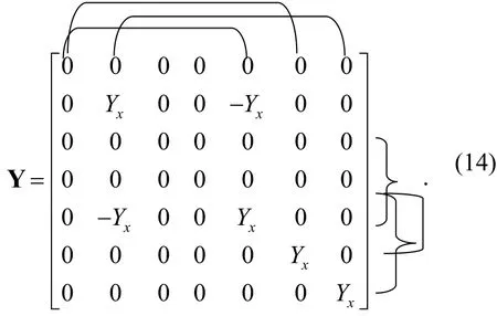
The equivalent pathological model for the BOCCCII described by (14) is shown in Fig. 4 (a).
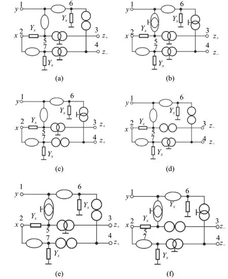
Fig. 4. One of four pathological models for (a) BOCCCII, (b)BOICCCII, (c) DOCCCII+, (d) DOCCCII–, (e) DOICCCII+, and(f) DOICCCII–.
Similarly, expanding (13) will yield four different forms of the expanded matrix stamps and bring about four equivalent nullor-mirror models. Fig. 4 (a) is one of them, the rest is omitted.
Again, starting from (13) and applying all possible combinations of the added pathological elements will yield four alternative different forms of the expanded matrixes, one of which is shown in (15), where the angle bracket located lower right corner is a current mirror connected row 7 and ground.
It is seen that this expanded matrix contains three different pairs of pathological elements and two floating admittances(Yx). One is connected between nodes 2 and 5, the other is connected between nodes 6 and 7.
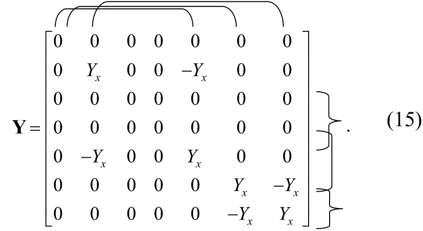
From (15), we can draw an alternative pathological model of the BOCCCII shown in Fig. 5 (a).
Similarly, expanding (13) will yield four alternative different forms of the expanded matrix stamps, leading to four alternative pathological models. Fig. 5 (a) is one of them, the rest is omitted. For other modified CCCIIs, in the same way,we can also obtain their port admittance matrixes, as depicted in Table 1. The corresponding pathological models are given in Figs. 4 (b) to (f) and Figs. 5 (b) to (f), respectively. Since each of them also possesses eight different forms, the modified CCCⅡ has 48 different forms of pathological models in all.
It can be readily seen that the BOCCCII possesses two classes of expanded matrix stamps and has eight different form pathological models.
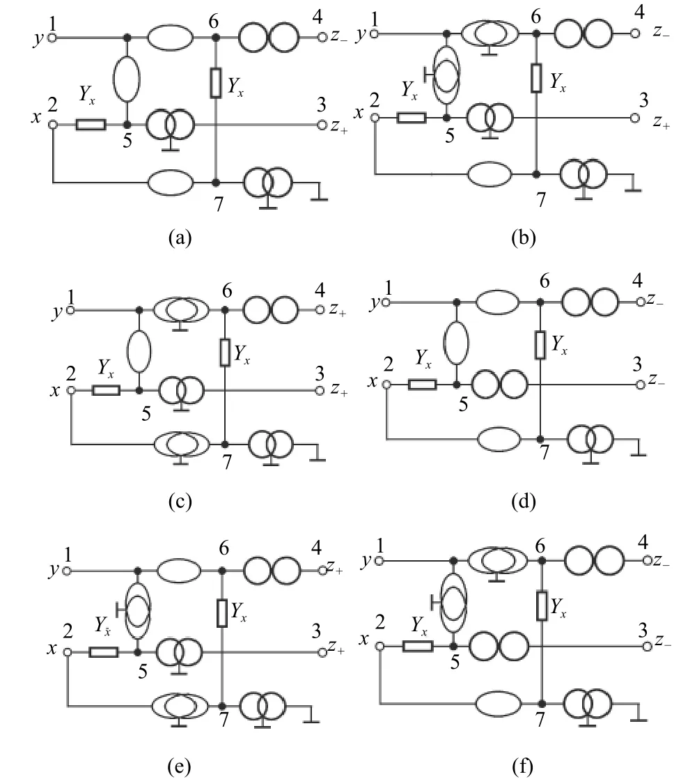
Fig. 5. One of four alternative pathological models for (a)BOCCCII, (b) BOICCCII, (c) DOCCCII+, (d) DOCCCII–, (e)DOICCCII+, and (f) DOICCCII–.

Table 1: Port admittance matrixes of the modified CCC
5. Conclusions
In systematic synthesis for pathological models for the CCCIIs, this is first paper. Moreover, we synthesize 48 new pathological models for the modified CCCII. The derived pathological models for the various CCCIIs will play an important role in circuit theory and applications.
 Journal of Electronic Science and Technology2018年2期
- Journal of Electronic Science and Technology的其它文章
- Multimedia Encryption with Multiple Modes Product Cipher for Mobile Devices
- Improved Method of Contention-Based Random Access in LTE System
- Model-Based Adaptive Predictive Control with Visual Servo of a Rotary Crane System
- Secure Model to Generate Path Map for Vehicles in Unusual Road Incidents Using Association Rule Based Mining in VANET
- Mining Frequent Sets Using Fuzzy Multiple-Level Association Rules
- Improvement of an ID-Based Deniable Authentication Protocol
