Monitoring and forecasting system for ship attitude motion based on extended Kalman filtering algorithm
2018-05-10 16:22:52SONGHuihuiYUGuoxingQUYanbin
中国惯性技术学报 2018年1期
SONG Huihui, YU Guoxing, QU Yanbin
(School of Information and Electrical Engineering, Harbin Institute of Technology at Weihai, Weihai 264209, China)
Ships are influenced by ocean status when voyaging on the sea. Bad circumstances will especially put sailings and ocean work in secure dangers. Therefore, it is essential for precisely monitoring and timely forecasting the ship attitude. Algorithm is important for ship attitude motion monitoring and forecasting. Currently,there are many algorithms, such as Kalman filtering algorithm[1], bow wave method[2], time series analysis method[3], and artificial neural network[4]. Compared with other approaches, the Kalman filtering algorithm has simple structure, strong applicability, good antiinterference and high stability[5], thus it is extensively used in human body motion tracking, inertial navigation,transportation, etc.[6-8].
The hard cores of the Kalman filtering algorithm are the establishments of the state equation and measurement equation. [9]utilizes an ensemble Kalman filtering algorithm to get over the difficulties of obtaining the model operator and the observation operator; [10-11]apply Kalman filtering to estimate parameters which are relevant to the accuracy of shop angular flexure measurement. [12-14]study Kalman filtering algorithm in ship attitude motion monitoring and forecasting. [12]acquires the dynamic ship position by an unscented Kalman filtering approach,and the influence of wind, currents and waves were considered. [13]develops a knowledge-based multitarget tracking methodology which uses unscented Kalman filter to deal with the priori information on the ship traffic and nonlinearities. [14]designs a sensor which can measure ship rolling, pitch and heaving parameters,and study the calibration model of the sensor; meanwhile the extended Kalman filter is used to achieve the optimal value of the parameters. However, the common problem of existing research is that the system accuracy is not high enough, what’s more now studies often ignore the impact of nonlinear model.
To resolve existing problems, this paper designs an inertial navigating system with acceleration sensors and a gyroscope cascaded together, which is utilized in monitoring rolling, pitch and yawing movement of ships. At the same time, non-perpendicularity correction is carried out on the sensors, and complementary processing and feedback adjustment both improve the precision of the output attitude angle. Moreover, system identification by the generalized least squares method establishes the ship status model and the corrected measurement model of the sensors, and then the Extended Kalman Filtering (EKF)algorithm optimizes the estimate status. The whole closed loop system further improves the precision of measurement and prediction. Additionally, a friendly interactive interface, which illustrates the current movement attitudes of the ship in 3D with the functions of real-time data storage, analysis, and processing, facilitates human interaction. Finally, the experimental results show the comparisons between the actual data, the measured data and the predicted data, that validate the monitoring and the forecasting functions design.
1 System overall designs
Ship attitude motion monitoring and forecasting system consists of inertial navigating module to monitor attitude motions and upper computer interface to analyze and process data. The two modules communicate by RS-232 serial communication.
1.1 Inertial Navigation Module
Inertial navigating module includes cascaded sensors,A/D converter, LCD, CPU and serial ports. As shown in Fig.1, attitude motion data-acquisition is performed by this cascaded system with three-axis acceleration sensors and three-axis gyroscope. The instrument adopts threeaxis acceleration sensors MMA 7361 made by Freescale and gyroscope L3G4220D. Due to different manufacture technologies, non-perpendicularity will exist among three axes. And MMA 7361 has poor short-term effects because its precision growing along with time, while L3G4220D has high precision in a short term but its precision decreasing because of error accumulation along with time. Therefore, non-perpendicularity corrections are carried on the acceleration sensors and gyroscope at first to improve the measurement precision of motion angles.
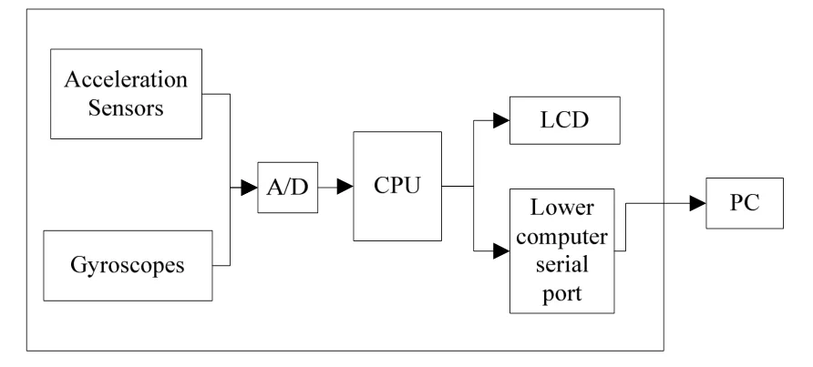
Fig.1 Inertial navigation module structure
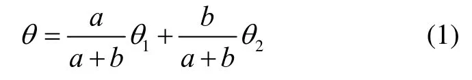
Taking consideration of complementary between frequency domains of the sensors, a complementary filtering method which designed according to Eq.(1), is utilized to improve the attitude measurement accuracy.
Meanwhile, a feedback adjustment system by comparisons actual motions in specific cases, such as 0°,30°, 60°, 90°, so as to further improve precision. Monitor principle is designed according to Fig.2, where two main functions are executed in CPU. One is attitude adjustment and complementary process, the other is feedback adjustment.
LCD5110 manufactured by Nokia is used for LCD display, which is convenient for observing data and debugging programs. Communication module realizes the communication with upper computer. Application of RS-232 serial communication in this module meets the design requirements and possesses data transmission stability.

Fig.2 Monitor principle in inertial navigating system
1.2 PC Interface
In this inertial navigating system, the PC interface consists of PC application module and algorithm module.
It can be observed from Fig.3 that the PC application module has storage, display, operation, Setting,warning and printing functions, which could be chosen on menu bar. The algorithm module includes filtering algorithm, motion equation and status prediction algorithm. Specifically, the filtering algorithm is utilized to eliminate interference noise, the motion equation transforms angle data into speed and displacement data, and the status prediction algorithm adopts the EKF algorithm to realize attitude motion forecast.

Fig.3 Structure of PC interface
2 Filtering and forecasting algorithm design
2.1 Ship state model
Ship model was traditionally built according to model experiments, however, because experiments are expensive, complex and long span, identifying theories began to be developed in establishing the ship status models gradually. The least squares identification is adopted in this inertial navigating system.
The ship motion equation is:
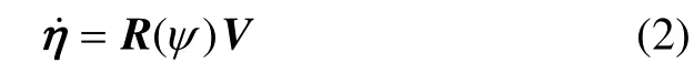
Where
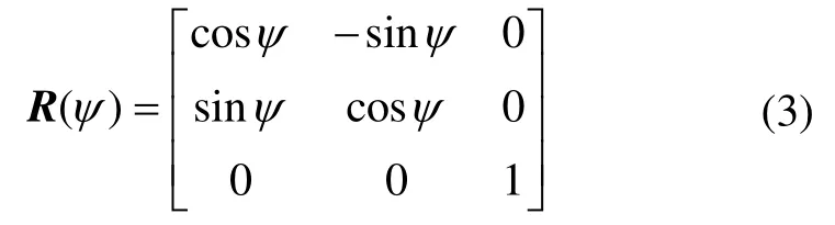
R(ψ) is the transformation matrix between earthbased coordinate system and ship hull coordinate system;shows the location (X,Y) in the earthbased coordinate system and the angular velocity of bow yawing;is complex motion of the ship which can be divided into sway, surge and yawing in the ship hull coordinate system.
And the state model of the ship[15]is:

Where

mis the mass of the ship;Izis the rotational inertia; the additional coefficients,are set according to [16];Tis the configuration matrix;μis the control signal;wis the disturbance from the environment.The damping matrixDand the coefficient of the thrustKare highly depend on the situation, thus their values both need parameter identification.
Parameter identification are solved by the generalized least squares method. The basic execution steps are as follows:
1) The model of the system is:

2) The residual of the system is:

where the convergence criteria is:
3) Utilize a Gaussian white noise as the input of aporder autoregressive model to gain the matrix vector:

where


Then, the estimated value can be obtained as:

4) Substitute the estimated value into the input sequence and the observation sequence:

5) Repeat steps 2), 3), and 4) with estimate identification parameters and which are solved by the generalized least square method until the iteration precision matches the anticipation.
According to the data from a real ship experiment,the identification result is shown in Table 1.
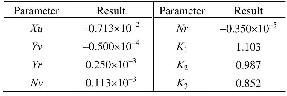
Tab.1 The parameters in the state model
2.2 Corrective measure model
Considering different manufacture technologies,three-axis sensors need non-perpendicularity corrections before use. As shown in Fig.4, we assume that axis r and axis s are perpendicular but axis t has angle deviation with r-s axis. Besides, sensors are supposed to have good linearity. We will use parameter identification method proposed by [17]to construct the corrective measure model so as to realize non-perpendicularity correction.

Fig.4 Diagram of non-perpendicularity of three axes
The Mathematical model of three-axis sensor can be expressed as:

According to Fig.4, the relationship of the three angles is shown in Eq.(15).
And there is a constraint, i.e.Combining Eq.(14) and Eq.(15), the corrective measure model is shown in Eq.(16).

After gaining enough data by changing sensors’attitude, parameter identification result via the generalized least square method is shown in Table 2.

Tab.2 Identification result of the measure model
2.3 EKF Design
The state equation and the measurement equation for EKF are:

whereX(k) represents system states at timek;μ(k) is control value at timek;Z(k) is measured value of sensors at timek;AandBare system parameters, which satisfy,B=TK;His measurement parameter.Q(k)andR(k) are noises from the processing and measuring.

WhereX(k|k-1) is the forecasting result at timekbased on the result at timek-1; is the control variable at time k;P(k|k-1) is the covariance matrix in accordance withX(k|k-1);X(k-1|k-1),X(k|k) are the optimum forecasting results at timek-1 and timek;Kg(k) is the Kalman gain;Q,Rare covariance matrixes ofQ(k), R(k) respectively.Through Eq.(19), the optimum forecasting states can be obtained iteratively.
2.4 Closed-loop Monitoring System Design
The main error sources of ships attitude motion monitoring and forecasting are: A.) measurement deviations in sensors; B.) simplification errors in state models and identification errors of parameters; C.) linearization errors of EKF and estimate deviations; D.) disturbance from environment. To minimize these errors, a closedloop control system is designed as Fig.5.

Fig.5 Block diagram of closed-loop monitoring system
By close loop feedback, errors which introduce from the factors of A), B) and D) could be considerable reduced. Meanwhile, a forecasting compensation link is also added to restrain the error from C) and to improve predicting precision, in which utilize estimating error from the former status to compensate the latter one’s parameters. It will strengthen the precision and the stability of the system.
3 Monitoring and forecasting system interface design
The PC interface of the ship attitude motion monitoring and forecasting system is programming by LabVIEW, which implements a set of capabilities including data collection, motion display, data storage,data analysis, danger warning and state recording, etc. To improve the visibility and operability, the main interface of the ship attitude motion monitoring and forecasting system is shown in Fig.6. This interface could be installed not only in PC system but also in other mobile devices.

Fig.6 The main interface
3.1 3D display interface design
3D display could be more intuitively illustrated the ship motion. By the combination of angle sensor data and alarm module, current motions of the ship including swaying, surging, yawing and whether in safe states or not are able to view in-depth. The data gathered are showed on 3D platform by displaying the 3D cube which is create from invoking the cube’s corner points calculated by rotation transformation based on the collected data. The display program is shown in Fig.7.

Fig.7 3D display program by labVIEW
3.2 Storage function program design
Storage module is used to save attitude data for later review, analysis and report conveniently. The module contains rapid storage programs and formatted storage programs. The rapid storage programs save the gathered attitude data as “HTML” format, and switch to store in another file automatically when the number of the gathered data sets reaches 400. The formatted storage files record marine conditions and data under certain circumstances, aiming at summarizing and reporting. This kind of storage program is shown in Fig.8.

Fig.8 Formatted storage program by labVIEW
3.3 Analysis function program design
Analysis module can realize data analysis of ship’s rolling and pitching at a certain time. It could show motion characteristics of the ship more specifically. This function program contains data loader and analysis programs, whose details are shown in Fig.9.

Fig.9 Analysis function program by labVIEW
4 Experimental verification
To verify the precision of the designed ship system,attitude motion monitoring and forecasting, we test the system and make a comparison among the data of the actual attitude, the measured attitude and the estimated attitude which represent the angle parameter with the initial value of 30° and the changing steps are 0.05°, 0.1°and 1° respectively in rolling, pitching and yawing. The actual dates are represented by industrial-grade digital display inclinometer SPI600 with the accuracy of 0.01°.
In Fig.10, the rolling angle is changed with different changing rates are shown in Fig.10 (a), (b) and (c). It can be observed that four steps whose height is 0.05 for each step are needed when the rolling angle change from 30°to 30.2° in Fig. 10 (a). In the same way, different step heights can be found in the other two subfigures. The actual, the measured and the estimated values are the black, the blue and the red curves respectively. This way is similar with Fig.11 and Fig.12 which show the dynamic of pitching angle and yawing angle. After comprehensive analysis of these three sets of data, it can be summarized out some following common characteristics of the experimental results.
When the ship is rolling or pitching, the error range of the measured angles are within 0.05°, while within 0.08°when the ship is yawing. It can also be observed from Figs. 10-12 (a) and (b) that the measured angle will has a slight spike at the moment of the actual angle changes, and then the spike quickly vanishes. The bigger the step amplitude is, the larger the spike happens.Fortunately, in the actual circumstances, the step won’t be too large due to high sampling rate. In addition, the measured angle has some individual points which have impulses, such as the sampling point 187 in Fig. 12 (a)and the sampling point 356 in Fig.12 (b). Because the occurrence frequency is low, the impulses can be filtered by low pass filter.

Fig.10 Rolling motion with different angles
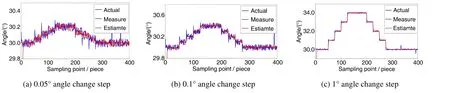
Fig.11 Pitching motion with different angles
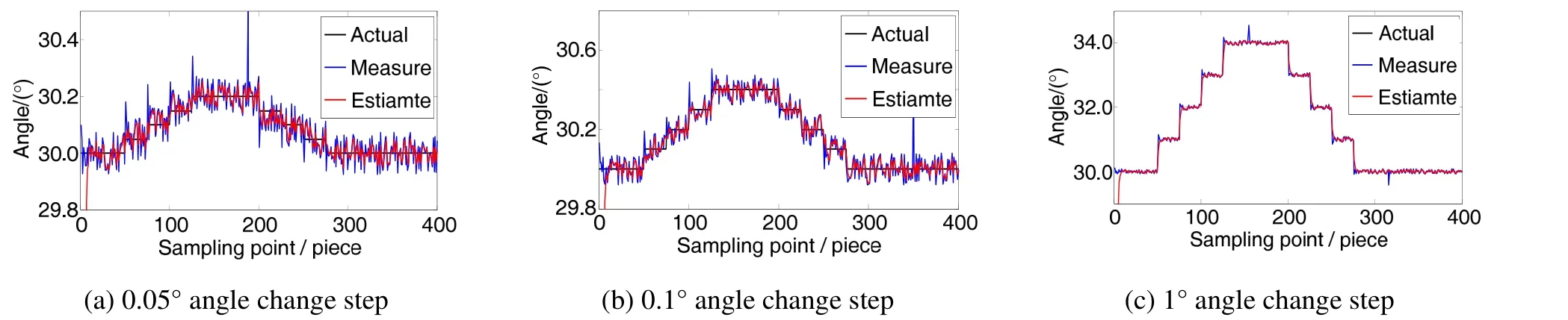
Fig.12 Yawing motion with different angles
The estimated angle can rapidly trace the change of the measured angle and the actual angle which can be seen from Fig.10-12. After about the tenth sampling point, the motion tendency of the estimated angle is consistent with the actual angle which illustrates that the timeliness of the forecasting function based to the EKF for this system is eligible. Compared with the measured angle, the estimated value is closer to the actual value. It indicates that the motion prediction based on the EKF owns high forecast accuracy. Moreover, there are no spikes exist in the estimated angle on account of the filter performance derived from the EKF module.
5 Conclusion
A ship attitude motion monitoring and forecasting system which can monitor and predict the rolling motion,pitching motion and yawing motion of the ship is designed in this paper. It can predict the attitude of the ship to avoid the risk and be useful for ensuring the security and stability. To improve the accuracy of the prediction, the correction of the sensor’s non-perpendicularity is studied, and the highly measurement precision can be obtained by complementary processing and feedback control. Meanwhile, we establish the state model for the ship and the measurement model for the corrected sensor by the generalized least squares method.We achieve the optimal estimated states by the EKF, and design a closed-loop system to reduce disturbance and stabilize this system. In view of the fact that the current system is weak to intercommunicate, a visual manmachine interface is designed to display the ship motion attitude in time and has the function of data analyzing and processing. Finally, the actual, the measured and the estimated angles when the ship motions under different change rates of three characteristic angles are compared by experiment. The results show that the designed ship attitude motion monitoring and forecasting system not only has high measuring and forecasting accuracy, but also has a satisfactory stability and rapid response.
[1]Lizeth T, Cristina V, Omar V H, Parameter identification of marine risers using Kalman-like observers[J]. Ocean Engineering, 2015, 93: 84-97.
[2]程超, 穆荣军, 蔡玲, 等. 基于遭遇波的艏前波法的航母姿态预报[J]. 中国惯性技术学报, 2015, 23(3): 409-414.Cheng C, Mu R J, Cai L, et al. Doppler interpolation method based on extrapolation and CIC filter[J]. Journal of Chinese Inertial Technology, 2015, 23(3): 409-414.
[3]Kim Y, Kim J H, Kim Y W. Time series prediction of nonlinear ship structural responses in irregular seaways using a third order Volterra model[J]. Journal of Fluids and Structures, 2014, 49: 322-337.
[4]Li D Q, Philip A W, Jiang Z Y, Zhao X. Establishment of metamodels for ship seakeeping performance using an effective approximation modeling method[J]. Journal of Ship Mechanics, 2016, 20(3): 243-257.
[5]Pascoal R, Gudeds S C. Kalman filtering of vessel motions for ocean wave directional spectrum estimation[J]. Ocean Engineering, 2009, 36(6-7): 477-488.
[6]Yun X P, Eric R B. Design Implementation and Experimental results of a quaternion-based Kalman filter for human body motion tracking[J]. IEEE Transaction on Robotics, 2006, 22(6): 1216-1227.
[7]Gu S S, Liu J Y, Zeng Q H, Liu P. A Kalman filter algorithm based on exact modeling for FOG GPS/SINS integration[J]. Optic, 2014, 125: 3476-3481.
[8]Hossein J, Maged D, Petros A I. Real time estimation of travel times along the arcs and arrival times at the nodes of dynamic stochastic networks[J]. IEEE Transaction on Intelligent Transportation Systems, 2008, 9(1): 97-110.
[9]Coelho F E, Hogan P, Jacobs G, et.al. Ocean current estimation using a multi-model ensemble Kalman filter during the Grand Lagrangian Deployment experiment(GLAD)[J]. Ocean Modelling, 2015, 87: 86-106.
[10]Zheng J X, Wu W, Dai D K. Influences of time synchronization error on angular flexure measurement of ship hull[J]. Journal of Chinese Inertial Technology, 2017, 25(2):151-155.
[11]Xu B, Duan T H, Wang Y F et al. Inertial measurement method of ship deformation based on IMM filtering[J].Journal of Chinese Inertial Technology, 2017, 25(1):22-27.
[12]Shi X C, Sun X Y, Fu M Y, Wen B, et.al. An unscented Kalman filter nased wave filtering algorithm for dynamic ship positioning[C]//IEEE International Conference on Automation and Logistics, 2011, 399-404.
[13]Gemine V, Paolo B, Jochen H. Knowledge based multitarget ship tracking for HF surface wave radar systems[J].IEEE Transactions on Geoscience and Remote Sensing,2015, 53(7): 3931-3949.
[14]Mao Y, Ming J L, Meng L D, et.al. Design and verification of the ship attitudes measuring and monitoring and analysis system[J]. Ship and Offshore Structures, 2014,24(10): 1-15.
[15]Fossen T I, Perez T. Kalman filtering for positioning and heading control of ship and offshore rigs[J]. IEEE Control System Magazine, 2009, 29(6): 32-46.
[16]Ding Y K, Yu M H. Parallel EKF identification methods for mathematics model of ship[J]. Ship Engineering, 2015,37(1): 72-74.
[17]林生荣, 张辉. 三轴加速度传感器矫正方法研究[J].2011, 30(11): 72-74.Lin S R, Zhang H. Study of three-axis acceleration sensor calibration method[J]. Transducer and Microsystem Technologies, 2011, 30(11): 72-74.
猜你喜欢
小哥白尼(军事科学)(2022年7期)2022-09-20 03:52:02
Chinese Physics B(2022年7期)2022-08-01 06:01:16
Chinese Physics B(2022年4期)2022-04-12 03:45:36
Chinese Physics B(2022年1期)2022-01-23 06:35:58
河北教育(教学版)(2021年10期)2022-01-14 03:55:30
Chinese Physics B(2021年12期)2021-12-22 06:41:50
书香两岸(2020年3期)2020-06-29 12:33:45
小哥白尼(军事科学)(2019年2期)2019-04-17 02:17:18
武大国际法评论(2019年6期)2019-04-09 02:49:52
小学生优秀作文(低年级)(2017年10期)2017-09-15 02:27:44