
Effect of process parameters on depth of penetration and topography of AZ91 magnesium alloy in abrasive water jet cutting
2018-04-22 03:03:12NiranjanSrinivasRamachandra
Journal of Magnesium and Alloys 2018年4期
C A Niranjan,S Srinivas,M Ramachandra
Department of Mechanical Engineering,BMS College of Engineering,Bengaluru-India
Abstract In the present study,the influence of dynamic process parameters such as water pressure,traverse speed and abrasive mass flow rate on depth of penetration and surface topography in high strength AZ91 magnesium alloy were investigated using Abrasive Water Jet(AWJ)cutting technology.Process parameters were varied at 3 levels and influences of each parameter on penetration ability were identified using analysis of variance(ANOVA).Contribution of water pressure and traverse speed on jet penetration found higher compared to abrasive mass flow rate.Profile projector was used to measure depth of penetration.Microstructural features and topography of cut surfaces were examined using Scanning Electron Microscopy(SEM).Micro cutting and ploughing were observed on the top and bottom portion of the cut which were similar to that of modes of deformation in other ductile materials like aluminium and steel.Surface roughness of cut surfaces was measured using Taylor Hobson surface roughness tester.Surface roughness found higher at higher traverse speeds and lower at lower traverse speeds.This study also highlights the suitability of AWJ cutting technology for cutting magnesium and its alloys.
Keywords:AZ91 magnesium alloy;Depth of penetration;Profile projector;Topography.
1.Introduction
Magnesium and magnesium alloys are currently gaining rapid attention by many manufacturing industries due to their unique lightweight and high strength property.By replacing aluminum and steel,magnesium and its alloys are considered to be the metal of future[1].Being the lightest of all structural materials Magnesium alloys are 33%lighter than Aluminum,75%lighter than steel and 61%lighter than Titanium[2,3].This light weight property makes them an apt choice for wide variety of applications in the field of automotive,aerospace,bio-medical,electronics and sports[4,5].Increasing demands for lightweight components urges the use of magnesium and its alloys.Magnesium also possesses innumerous benefits like high specific stiffness,rigidity,specific strength,excellent cast ability,and high damping capacity[6-8].However magnesium and its alloys are associated with machining difficulties at elevated temperatures over 600°C and are having limited deformation systems.HCP crystal structure makes them difficult to deform[9,10].There is a possibility of ignition of chips at higher cutting speeds in dry machining of magnesium and its alloys[11].Many researches have been carried out to prevent ignition of chips through Conventional machining techniques by modifying the tool geometries and use of cutting fluids[12-16]
The application of lubricants during conventional machining of magnesium and its alloys has been widely discussed topic.Water and water-based coolants may be used as a lubricant but under certain conditions(at elevated temperatures)magnesium decomposes water to form hydrogen gas,which is highly explosive and may increase risk of fire[17].Due to these difficulties,many researchers have denied the use of water and water-based coolants and preferred common practice of dry machining or machining with the use of mineral oil[18].However proper care should be taken during high cutting speeds so as to prevent fl ank built-up edges(FBU)on tools.Presence of FBU on tools reported with increase in cutting forces and surface roughness[19].Even though development of several newer tooling systems has contributed positively to improve the quality of machining,these systems have resulted in higher processing costs.Cost-effectiveness processing of magnesium and its alloys are therefore essential in order to apply and expand their applications.
Limited studies are reported on machining of magnesium and its alloys through few nontraditional machining processes such as laser assisted machining and Electric Discharge Machining(EDM).Rizwan Abdul et al.[20]analyzed the surface of AZ91 magnesium alloy,which was removed by laser and reported that main cutting force and feed force were reduced during laser assisted machining when compared to conventional machining.However formation of long,curled chips affected effectiveness of material removal process and it was revealed that during machining,chips were ignited when brought in contact with the laser beam.Present study aims to overcome these difficulties in machining magnesium and its alloys through one of the most efficient non-traditional machining for all the materials i.e.Abrasive Water Jet(AWJ)machining.AWJM provides better and risk free machining possibilities compared to other processes due to various distinct advantages such as no thermal distortion,no potential fire hazard,absence of tool wear,lower cutting forces(less than 10N),higher fl exibility and moreover the properties of work materials remain unchanged[21,22].AWJM technology is considered to be superior to other machining technologies in processing wide range of materials[23]and especially for processing thermally sensitive materials like magnesium and its alloys.
Being the most important in industrial applications,depth of penetration and surface quality decides the efficiency,performance and process capability of water jet cutting.Over past decade theoretical and experimental investigations were conducted to know the cutting performance of ductile materials such as aluminium and its alloys,mild steel,stainless steel,copper,brass etc.,with AWJ cutting technology[24-26].But Limited literature is available on AWJ machining of magnesium and its alloys.An attempt is made to analyze the effect of dynamic process parameters on depth of penetration and surface topography.Material removal mechanisms were also analyzed.
2.Experimental setup
OMAX 1515 AWJ cutting system of pressure capacity 100MPa to 345MPa supported with 30 Hp direct drive pump was used for execution of experiments.The equipment is also featured with gravity feed type abrasive hopper,pneumatically controlled X-Y-Z movements(1575×1575×150mm)and traverse speed range of 1mm/min to 8000mm/min.A 0.35mm sapphire orifice with tungsten carbide focusing nozzle of diameter 0.76mm were used(based on specifications and capacity of the AWJ cutting equipment)to accelerate thewater jet containing mixture of air and abrasive.All the cutting experiments were carried out using 80 mesh garnet particles.Table 1 shows the chemical composition of Magnesium AZ91 alloy.Specimen was cut into trapezoidal shape to make through cuts as shown in Fig.1.This method of making trapezoidal shape is quite popular to find out depth of penetration.
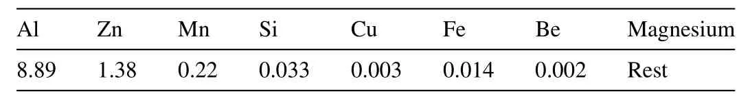
Table 1 Chemical compositions(wt%)of the AZ91 Magnesium alloy.

Fig.1.AWJ cutting of trapezoidal Specimen.
AWJ cutting involves various parameters such as hydraulic parameters(Orifice diameter and water pressure),abrasive parameters(abrasive material,mass flow rate),cutting parameters(traverse speed,standoff distance,target material,angle of attack)etc.,All these parameters are having their own effect on target parameters such as depth of penetration,kerf width,kerf quality,surface roughness etc.,as noted by hashish[27].It is difficult to consider all the input and output parameters to analyze the capability of target material.Present study focuses on important output parameters such as depth of penetration and surface roughness under different cutting conditions.Input dynamic parameters such as water pressure,traverse speed and mass flow rates were selected and varied at 3 levels during the experimentation.The appropriate values for input variables were selected based on preliminary experiments[28].Table 2 describes the details of cutting conditions including dynamic and constant parameters.
SEM images were taken to study the surface characteristics and Nikon D3300 24.2 MP Digital SLR Camera was used to capture the full profile of cut surfaces.Surface roughness of the selected specimens under different input conditions were measured using Taylor Hobson surface roughness measuring instrument.Surface roughness was measured on a surface length of 7.2mm with cut off distance 0.8mm.

Table 2 Cutting conditions for experiments.
3.Design of experiments
Planning of experiments and optimization of process were done through Taguchi’s technique by considering dynamic parameters varied at three levels.Taguchi’s method gives better interaction of process parameters and provides systematic predictions to analyze the process effectively with minimum number of experiments[29].This method uses a design of orthogonal arrays to determine the optimal process parameters with respect to performance measure in terms of depth of penetration,surface roughness,kerf width etc.,Based on different levels selected for input factors such as water pressure,traverse speed and mass flow rate L27 orthogonal array was chosen to conduct experiments.The experimental layout of L27(33)array including factors and their levels are given in the Table 3.
Analysis of Variance(ANOVA)was used to identify the influence of each input parameters on depth of penetration.For interpreting test statics,F-ratio and P-values were used to know the significance of input parameters and this analysis was carried out by considering 95%confidence level.It is believed that,if the F-ratio of the input parameter is greater than F-critical value of the statistic table then the input parameter is considered to be significant and has influence on output parameter.If F-ratio value is less than F-critical then input parameter is considered to be insignificant and has no effect on output parameter.Similarly P-value indicates the significance of process parameters.If the P-values are less than 0.005 for 95%confidence level then the results are most significant otherwise it is considered to be insignificant and has no effect on output.
4.Method of findin depth of penetration
There are different methods available for finding depth of penetration in previous literature.Several authors have considered bottom length of cut in a trapezoidal specimen to calculate total depth of penetration using relation ht=L Sin θ(where htis depth of penetration,L is length of cut at bottom of specimen and θ is angle of trapezoid).Yuvraj and Pradeep in their studies have used dial gauge for measuring depth of penetration in AA5058-H32 aluminium alloy by consideringlength of cut(L)on work piece surface with predetermined length of traverse[30].

Table 3 Experimental layout of L27 orthogonal array.
Other methods include inserting the fine needle at the end of kerf of non through cuts on specimens and depth of penetration is measured[31].In this method once the cut is made on specimen,multiple measurements were taken throughout the entire length of the cut using needle and sample should be cut open to ensure the depth by exposing peaks in cut.Generally measurement is taken on the top of highest peak and this is quite difficult,time consuming and less practical.And later method is to cut the specimens on wedge block at fixed cutting speeds then depth of penetration is measured at the end of kerf[32].The accuracy of the measured values may be affected in these methods,since it requires ordinary instruments like steel rule and height gauges to measure depth of penetration.In this present study,profile projector was used to measure length of cut(L)on inclined surface and exact depth of penetration(dp)was calculated.Values of length of cut can be obtained in three decimal places.This cannot be possible by ordinary measuring instruments like steel rule and height gauge.Hence this method of finding depth of penetration gives accurate values compared to other methods.Fig.2 shows the geometry of trapezoidal specimen used to measure the length of cuts.
Cuts were made on trapezoidal specimen and specimen was placed on a glass base of profile projector.A ray of light source was passed through cuts made by abrasive water jet as shown in Fig.3.A shadow of each cuts were projected upon the display screen of profile projector as shown in Fig.4 then the length of each cut was taken by measuring distance between start and end of cut.

Fig.2.Geometry of trapezoidal specimen.

Fig.3.Specimen placed on glass base of profile projector.
Measurements of all 27 cuts were taken with the help of digital measuring unit.Since light will not pass through opaque material,shadow gives exact length of cuts.Fig.5 shows representation of lights passing through cuts L1 and L2.Relationship of depth and length of cut is given in Fig.6.Actual depth of penetration is calculated using the equation dp=L tan θ
5.Results and discussions
5.1.Effect of input parameters on depth of penetration
Effect of control factors such as water pressure,traverse speed and mass flow rate on depth of penetration was analyzed by considering mean values of depth of penetration.Trends observed for different cutting conditions are discussed below.
·Effects of water pressure on depth of penetration
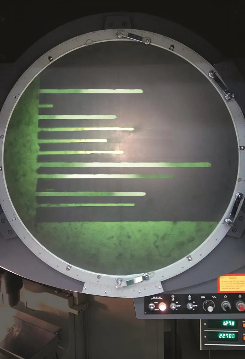
Fig.4.Length of cuts projected upon the display of profile projector.
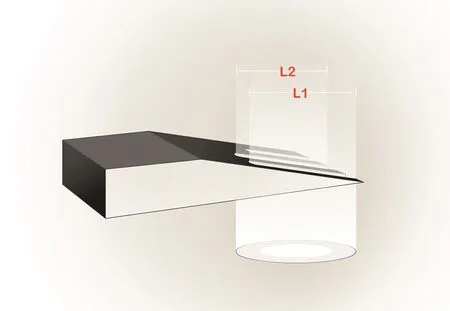
Fig.5.Light passing through cuts.
Fig.7 shows general trend of depth of penetration observed during cutting of AZ91 magnesium alloy.Similar trend was observed in cutting other ductile materials such as mild steel and stainless steel[27].Depth of penetration generally increase with increase in water pressure,due to the fact that the kinetic energy of water and abrasive particles will increase with increase in water pressure.Water pressure remains dominant in deciding depth of penetration and influences the distribution of water and abrasive particles.
·Effects of traverse speed on depth of penetration
Fig.8 shows the relationship between traverse speed and depth of penetration.Similar relationship was obtained in cutting mild steel and aluminium alloy[33].It was observed that the dependency on depth of penetration for AZ91 magnesium alloy is significant at lower traverse speeds,insignificant at higher traverse speeds.Increasing the traverse speed lowers the impact of numbers of abrasive particles and results in decreasing the depth of penetration.In contrast,the influence of traverse speed on depth of penetration lies on exposure time of abrasive water jet.Lesser the exposure time more the depth of penetration.

Fig.6.Depth of penetration relationship.

Fig.7.Effect of pressure on depth of penetration.
·Effects of mass flow rate on depth of penetration
Fig.9 shows the effect of mass flow rate on depth of penetration.It was observed that the relationship of mass flow rate and depth of penetration was increased initially.That is increase in mass flow resulted in increase in depth of penetration due to participation of large number of abrasive particles in cutting.However,after reaching threshold value of mass flow rate,depth of penetration decreases as the higher flow rates sometimes blocks the nozzle.Further at higher abrasive mass flow rates,due to some damping mechanisms such as generation of water-solid films and abrasive particles collision usually occur in mixing chamber significantly reduces the specific energy of abrasive particles[34].It is evident from the previous studies that the velocity of abrasive particles decreases with an increase in abrasive mass flow rate[35-37].Thus reduces the depth of penetration.

Fig.8.Effect of traverse speed on depth of penetration.
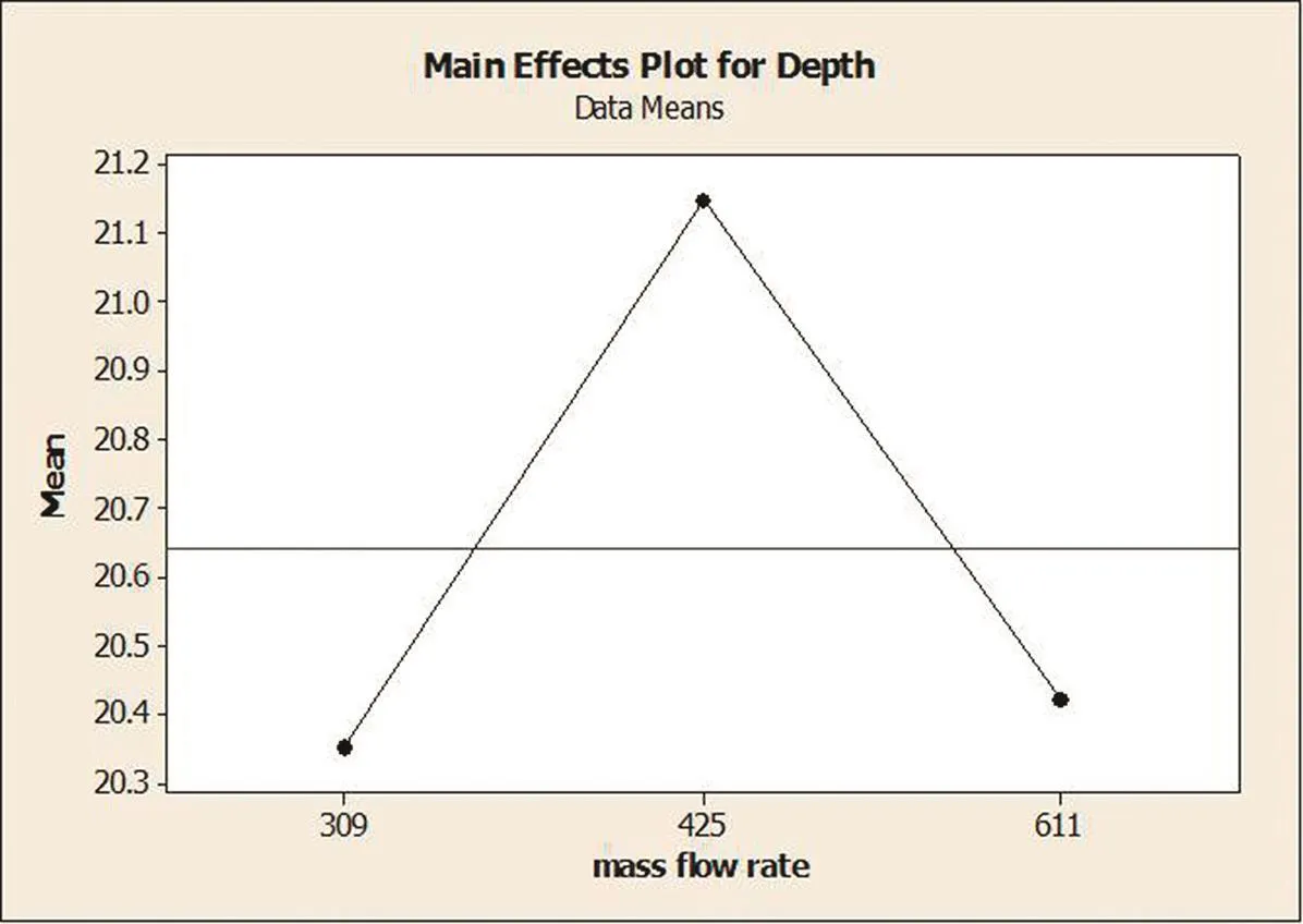
Fig.9.Effect of mass flow rate on depth of penetration.
5.2.Analysis of variance(ANOVA)
Table 4 shows Analysis of Variance for depth of penetration.Initially F-ratio was calculated from the result obtained for 27 experiments then compared to the critical value obtained from statistical F-test.F values for both pressure and traverse speed found greater than critical values.Further P values obtained for pressure and traverse speed are less than 0.005.Therefore it is clear that statistical test is significantwith the confidence level(95%)selected for conducting the experiments.F critical value and P value for mass flow rate was found larger than the statistical values.This indicates that mass flow rate is having least influence on depth of penetration and it is insignificant.From the Table.4 pressure and traverse speeds were found more significant factors which infl uences depth of penetration by 53.64%and 35.11%respectively.Mass flow rate was found least significant with 0.081%contribution to the depth of penetration.
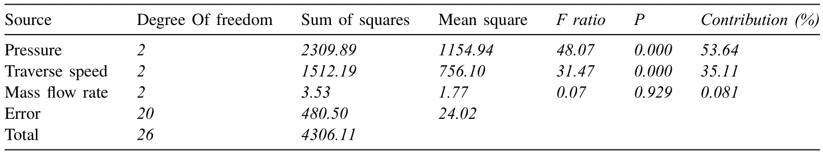
Table 4 Results of ANOVA for depth of penetration.

Fig.10.Types of deformation.
5.3.Topography of cut surfaces
Literatures have witnessed solid particle impact in material removal process by abrasive water jets by erosion[38].In ductile materials,material removal process are divided into two zones such as micro cutting zone observed at the top surface and deformation zone occurs at bottom surface[39].In micro cutting region,material is removed due to sharp edged and angular abrasive particles at low cutting depths.Impact of the abrasive particles at shallow angles promotes micro cutting,termed as ‘cutting wear’.At larger cutting depths,the impact angle of abrasive particles becomes more obtuse and causes ‘deformation wear’.Ploughing is responsible for material removal in the bottom region due to spherical abrasive particles[40].Deformation wear zone is affected by surface waviness caused due to instabilities of water jet.Loss of jet energy reduces the capacity of material removal.Waviness of the cut surface divides cutting and deformation wear zones as shown in Fig.10.

Fig.11.Deformation mechanism involved in AZ91 magnesium alloy.

Fig.12.Different Regions in cut surface.
In the present study,deformation of AZ91 magnesium alloy was observed similar to deformation in other ductile materials[41-43].SEM images Fig.11(a)and(c)clearly indicate that,material was removed due to cutting deformation and ploughing deformation at the top and bottom regions of cut surface.Further Fig.11(b)reveals plastic deformation at top region caused by scratching of abrasive particles and lips are observed at the edges of crater.Overlapped craters and separated wear tracks at bottom region caused due to plowing of round abrasive particles can be observed in Fig.11(d).The topography of cut surfaces uplifts the previous assumptions of micro-cutting and ploughing deformation mechanisms which are responsible for ductile behaving materials.
5.3.Surface roughness
In abrasive water jet cutting,cut surfaces are divided into three zones such as Initial Damage Zone(IDZ),Smooth Cutting Zone(SCZ)and Rough Cutting Zone(RCZ)as shown in Fig.12[40-42].In IDZ the cut surfaces are free from irregularities and tracks of wear.Surface roughness at this zone is usually less due to repeated impact of sharp edged abrasive particles combined with waterjet.In the SCZ,initially the surfaces are clear and smooth but affected by formation of uniform wear tracks in the direction of jet traverse at the bottom portion of the SCZ.Since this zone is sheared by both micro cutting and deformation modes,surface roughness increases further down the surfaces.The RCZ shows the presence of deviated wear tracks with waviness produced by stream of deflected water jet.The embedment of spherical abrasive particles and pocket like structures are observed at the shallow impact angles as shown in Fig.11(c).(d).the surface roughness at this zone is higher than other two zones.In the present study average of 5 readings of surface roughness was considered in all the three regions.

Fig.13.Topography and surface roughness of cut surfaces of AZ91 magnesium alloy under different conditions.
Since it is difficult to mount and measure surface roughness of specimens below 20mm thickness,only specimens having more than 20mm thickness were considered to measure surface roughness.Fig.13 shows the cut surfaces with roughness values of selected specimens having thickness more than 20mm.The surface roughness values for all the three regions found increased with increase in traverse speeds.Surface roughness of IDZ increased from 4.55 to 7.325 μm,5.3 to 9.66 μm for SCZ and 7.033 to 17.35 μm for RCZ.Surface roughness found minimum at lower traverse speeds this is due to increase in impact of number of abrasive particles and exposure time.
Surface roughness is also a function of water pressure because kinetic energy of water jet increases the velocity of particles which in turn increases the surface quality and also the influence of abrasive mass flow rate on surface roughness depends mainly on water pressure.However at higher traverse speeds,increase in water pressure increases the surface roughness.Hence traverse rate is the most significant parameter in deciding the quality of cut at all the three zones.
6.Conclusions
The influence of input parameters on depth of penetration and surface topography in AWJ cutting of AZ91 magnesium alloy was presented.It was observed that,depth of penetration is a function of pressure which influences more than traverse speed.From ANOVA,water pressure found more significant with 53.64%contribution,followed by traverse speed with 35.11%contribution and mass flow rate has no effect on depth of penetration,however combination of mass flow rate with water pressure increases the penetration in target material.Optimal input conditions for maximum depth of can be obtained at 300MPa(Pw),150mm/min(ts)and 425g/min(mf).Use of profile projector to find depth of penetration found simple and more suitable than other methods.SEM observations conclude the material removal mechanism for AZ91 magnesium alloy was similar to other ductile materials.Surface quality of cut surfaces is a function of traverse speed.Lower the traverse speeds higher the surface quality.Lowest surface values were recorded as 4.55μ (IDZ),5.3μ (SCZ)and 7.03μ (RCZ)for input conditions 300 MPa(Pw)150mm/min(ts)and 425g/min(mf)and these values can be considered as optimum values of surface roughness.Highest surface values were obtained as 7.325 μ (IDZ),8.175 μ (SCZ)and 17.35 μ (RCZ)for cutting conditions 200MPa(Pw),300mm/min(ts)and 611g/min(mf).Pressure remains dominant parameter in deciding depth of penetration and traverse speed is most significant factor for surface roughness measurement.No fire hazards and ignition of chips were observed during cutting.Overall it can be concluded that AWJ cutting is the viable and risk free technology for processing magnesium based alloys.
Acknowledgments
The authors would like to express their sincere thanks and appreciation to Center of Excellence(CoE)in advanced materials research and TEQIP,BMS College of Engineering,Bengaluru,Karnataka,India,for providing financial assistance in conducting this research work.
 Journal of Magnesium and Alloys2018年4期
- Journal of Magnesium and Alloys的其它文章
- Review on friction stir welding of magnesium alloys
- Rietveld re finement of powder X-ray diffraction,microstructural and mechanical studies of magnesium matrix composites processed by high energy ball milling
- Effect of Si addition on microstructure and wear properties of Mg-Sn as-cast alloys
- Atomistic calculations of surface and interfacial energies of Mg17Al12-Mg system
- Corrosion protection of AZ91D magnesium alloy by acerium-molybdenum coating-The effect of citric acid as an additive
- The corrosion behavior and mechanical property of the Mg-7Y-xNd ternary alloys